This paper deals the video motion estimation and compensation is a part of the encoding technique which helps to determine the correct motion vector as well as reduce the error caused due to redundancies between successive frames in video images. This motion estimation and compensation technique is widely applicable in security systems and motion tracking systems in robotics. This paper deals with developing a efficient multiple search algorithm which can overcome the drawbacks of existing algorithms like center based diamond search algorithm and three step search algorithm. The proposed algorithm avoids useless search thereby improves computational time, speed as well as it has multiple search characteristics which helps to reduce the mean square search and give better search results thereby resulting in better motion vector detection even for a smaller motions specially employed in stereovision system.
Keywords |
| Block matching, Stereovision system, Motion estimation, minimum block distortion point (MBD). |
INTRODUCTION |
| The increase demand to incorporate video data into telecommunications services, the corporate environment, in
entertainment industry, in robotics and even at home has made digital video technology an essential one. A problem
however is that still image and digital video rates are very large ,consume lot of bandwidth and storage space etc.For
this reason ,Video compression standards have been developed to eliminate picture redundancy, allowing the video
information to be transmitted and stored in a compact and efficient manner with better video quality. In general,
successive pictures in a motion video sequence tend to be highly correlated, that is, the picture changes slightly over a
small period of time. |
| This implies that the arithmetic difference between these pictures is small. For this reason, compression ratios for
motion video sequences may be increased by encoding the arithmetic difference between two or more successive
frames. In contrast, Objects that are in motion increase the arithmetic difference between frames which in turn implies
that more bits are required to encode the sequence. To address this issue, motion estimation is utilized to determine the
displacement of an object in motion. It is a process by which elements in a picture are best correlated to elements in
other picture (a head or behind) by this estimated amount of motion. The amount of motion is encapsulated in the
motion vector.Foreward motion vectors refer to correlation with previous pictures. Backward motion vectors refer to
correlation with future pictures. An efficient motion estimation algorithm increases frames correlation, which in turn
minimizes pixel arithmetic difference. |
RELATED WORK |
| The result obtained in not only higher compression ratios but also in high quality decoded video sequence. Motion
estimation is an extremely computationally intensive operation difficult to implement in real time .For this reason, a
variety of motion estimation algorithm have been implemented by the industry. Various motion estimation algorithm
were analysed and proposed algorithm was preferred because of its best search result, improves computational time,
speed as well as it has multiple search characteristics this can be very helpful for stereo vision systems like stero vision
robot for tracking the obstacles and it also used in security system. |
BLOCK BASED MOTION COMPENSATION |
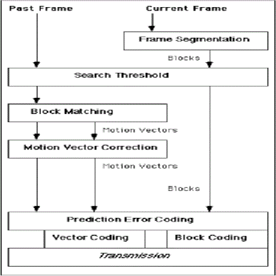
| Block based motion compensated video compression takes place in a number of distinct stages. The flow chart above
illustrated below shows how the output from the earlier processes forms the input to later processes. Consequently
choices made at early stages can have an impact of the effectiveness of later stages. To fully understand the issues
involved with this type of video compression it is necessary to examine each of the stages in detail. |
| These stages can be described as |
| Frame Segmentation |
| Search Threshold |
| Block Matching |
| Sub-Optimal Block Matching Algorithms |
| Motion Vector Correction |
| Vector Coding |
| Prediction Error Coding |
| Frame Segmentation |
| The current frame of video to be compressed is divided into equal sized non-overlapping rectangular blocks. Block size
affects the performance of compression techniques. The larger the block size, the fewer the number of blocks, and
hence fewer motion vectors need to be transmitted. However, borders of moving objects do not normally coincide with
the borders of blocks and so larger blocks require more correction data to be transmitted Small blocks result in a greater
number of motion vectors, but each matching block is more likely to closely match its target and so less correction data
is required. The block size is too small then the compression system will be very sensitive to noise Thus block size represents a trade off between minimizing the number of motion vectors and maximizing the quality of the matching
blocks. |
| Search Threshold |
| If the difference between the target block and the candidate block at the same position in the past frame is below some
threshold then it is assumed that no motion has taken place and a zero vector is returned. Thus the expense of a search
is avoided. Most video codec’s employ a threshold in order to determine if the computational effort of a search is
warranted. |
| Block Matching |
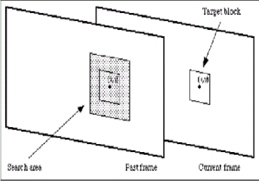
| Block matching is the most time consuming part of the encoding process. During block matching each target block of
the current frame is compared with a past frame in order to find a matching block. When the current frame is
reconstructed by the receiver this matching block is used as a substitute for the block from the current frame. Block
matching takes place only on the luminance component of frames. |
| The colour components of the blocks are included when coding the frame but they are not usually used when
evaluating the appropriateness of potential substitutes or candidate blocks. The search can be carried out on the entire
past frame, but is usually restricted to a smaller search area centered on the position of the target block in the current
frame. |
| This practice places an upper limit, known as the maximum displacement, on how far objects can move between
frames, if they are to be coded effectively. The maximum displacement is specified as the maximum number of pixels
in the horizontal and vertical directions that a candidate block can be from the position of the target block in the
original frame. |
| The quality of the match can often be improved by interpolating pixels in the search area, effectively increasing the
resolution within the search area by allowing hypothetical candidate blocks with fractional displacements. |
Sub-Optimal Block Matching Algorithms |
| The exhaustive search is computationally very intensive and requires the distortion function to be evaluated many times
for each target block to be matched. Considerable research has gone into developing block matching algorithms that
find suitable matches for target blocks but require fewer evaluations. Such algorithms test only some of the candidate
blocks from the search area and choose a match from this subset of blocks. Hence they are known as sub-optimal
algorithms. Because they do not examine all of the candidate blocks, the choice of matching block might not be as good
as that chosen by an exhaustive search. |
Motion vector correction |
| Once the best substitute, or matching block, has been found for the target block, a motion vector is calculated. The
motion vector describes the location of the matching block from the past frame with reference to the position of the
target block in the current frame. Motion vectors, irrespective of how they are determined, might not correspond to the
actual motion in the scene. This may be due to noise, weaknesses in the matching algorithm, or local minima. The
property that is exploited in spatially dependent algorithms can be utilized after the vectors have been calculated in an
attempt to correct them. Smoothing techniques can be applied to the motion vectors that can detect erratic vectors and
suggest alternatives. |
Vector coding |
| Once determined, motion vectors must be assigned bit sequences to represent them. Because so much of the
compressed data will consist of motion vectors, the efficiency with which they are coded has a great impact on the
compression ratio In fact up to 40% of the bits transmitted by a codec might be taken up with motion vector data
fortunately, the high correlation between motion vectors and their non-uniform distribution makes them suitable for
further compression. This compression must be lossless. Efficient coding of motion vectors is a subject of research in
its own right and many authors have offered suggestions on which techniques work best. Any one of the lossless
general purpose compression algorithms is suitable for coding vectors |
Prediction Error coding |
| Although the battery of techniques described thus far can code video very successfully, they rarely generate perfect
replicas of the original frames. Thus the difference between a predicted frame and the original uncompressed frame
might be coded. Generally this is applied on a block by block basis and only where portions of the coded frame are
significantly different from the original. Transform coding is most frequently used to achieve this and completely
lossless coding is rarely a goal. |
VIDEO CODEC |
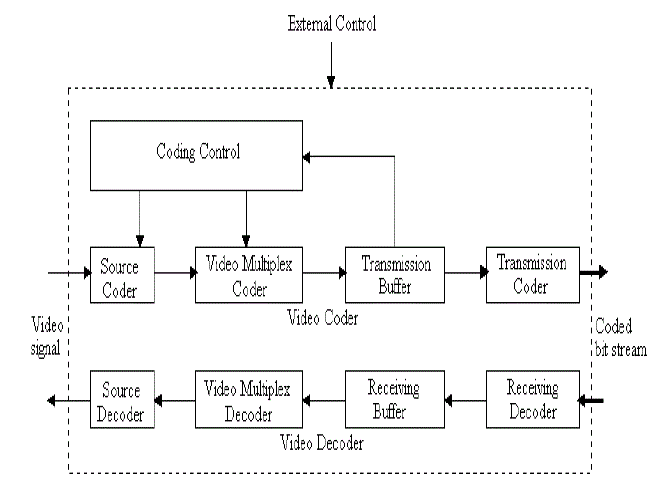
| A video codec is a device is software that enables compression or decompression of digital video. The compression is
usually lossy. Historically, video was stored as an analog signal on magnetic tape. Around the time when the compact
disc entered the market as a digital-format replacement for analog audio, it became feasible to also begin storing and
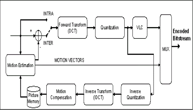
using video in digital form and a variety of such technologies began to emerge. a high level picture of a video encoder,
applicable to MPEG-2, MPEG-4 or H.264 standards. As digital “raw” video arrives at the encoding pipeline, a series of
transforms are applied with the purpose of removing redundant information (lossless) or irrelevant information (lossy)
exploiting characteristics of the human visual system (HVS). One important aspect of a video encoder is the removal of
temporal redundancy. This is achieved by the Motion Estimation (ME) block in the encoder. |
| The objective is to represent each video frame as a difference in pixel values from a reference frame. The reference
frame can be one or more past frames in the video sequence or frames in the future. Frames, or frame portions, not
predicted from references are nominated as INTRA, frames, or frame portions, predicted from a reference are known as
INTER. The selection of whether to encode as INTRA or INTER is based on the temporal predictability of the frame or
frame portion with respect to the reference. |
| Typical motion estimation algorithms account for a substantial portion of the application CPU cycles, and in many
cases (depending on the complexity of the algorithms) it’s been known to account for as much as 60% of total CPU
cycles. |
| The idea is to achieve bit rate reduction without sacrificing the quality of video signal. |
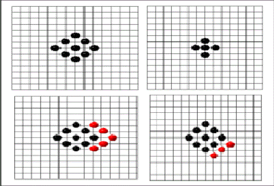
| Therefore, this paper targets the analysis of the Motion Estimation algorithms in typical processor micro-architectures
with on-chip memory, The proposed algorithm uses the same type of patterns used in diamond search algorithm with a
reduction in a step size. Based on the location of the minimum block distortion point (MBD) point, the number of
checking points to be used in the successive steps varies. The search pattern shows in the figures 5. |
| The number of searching steps is reduced to three and the Small Diamond search pattern (SDSP) search is reached at
the third step regardless of the location of the MBD point. The Large Diamond Search Pattern (LDSP) is repeatedly
used until the centre point becomes the MBD point. The algorithm is summarized as follows. The number of searching
steps is reduced to three and the SDSP search is reached at the third step regardless of the location of the MBD point
Thus the compact configuration and reduced number of search points provides an improved performance than the other
existing algorithms. the centre point becomes the MBD point. Thus the compact configuration and reduced number of
search points provide an improved performance than the other existing algorithms given below. |
Algorithm |
| Step 1: Initial LDSP is centered at the origin of the search window. Now, test each point in the Search pattern. If the
MBD point is the center point go to step3. Otherwise go to step2. |
| Step 2: Form a new LDSP with the MBD point as the center point. If the new MBD point is at the center position, go
to step3. Otherwise repeat this step for one more time. |
| Step 3: Form the SDSP with previous MBD point as the center point. The new MBD point obtained in this step
becomes the final solution i.e., the motion vector (x, y). The number of search points depends on the location of MBD
point also determines the search direction. |
STEREO VISION SYSTEM |
| Two cameras are used, mounted with different perspectives of an object, and calibration techniques are used to align
pixel information between the cameras and extract depth information. This is most similar to how our brains work to
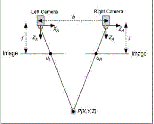
visually measure distance. The diagram of a simplified stereo vision setup, where both cameras are mounted perfectly
parallel to each other, and have the exact same focal length. |
| The variables in Figure 6 are: |
| b is the baseline, or distance between the two cameras |
| f is the focal length of a camera |
| XA is the X-axis of a camera |
| ZA is the optical axis of a camera |
| P is a real-world point defined by the coordinates X, Y, and Z |
| uL is the projection of the real-world point P in an image acquired by the left camera |
| uR is the projection of the real-world point P in an image acquired by the right camera |
| Since the two cameras are separated by distance “b”, both cameras view the same real-world point P in a different
location on the 2-dimensional images acquired. The X-coordinates of point’s uL and uR are given by: |
| uL = f * X/Z and uR = f * (X-b)/Z |
| Distance between those two projected points is known as “disparity” and we can use the disparity value to calculate
depth information, which is the distance between real-world point “P” and the stereo vision system. |
| Disparity = uL – uR = f * b/z |
| Depth = f * b/disparity |
| Stereo vision systems are best suited for applications in which the cameras settings and locations are fixed, and won’t
experience large disturbances. Common applications include navigation, industrial robotics, automated inspection and
surveillance. |
STEREO VISION SYSTEM APPLICATIONS |
| Stereo vision systems are best suited for applications in which the cameras settings and locations are fixed, and won’t
experience large disturbances. Common applications include navigation, industrial robotics, automated inspection and
surveillance. |
Navigation |
| Autonomous vehicles use depth information to measure the size and distance of obstacles for accurate path planning
and obstacle avoidance. Stereo vision systems can provide a rich set of 3D information for navigation applications, and
can perform well even in changing light conditions. |
Industrial Robotics |
| A stereo vision system is useful in robotic industrial automation of tasks such as bin picking or crate handling. A binpicking
application requires a robot arm to pick a specific object from a container that holds several different kinds of
parts. A stereo vision system can provide an inexpensive way to obtain 3D information and determine which parts are
free to be grasped. It can also provide precise locations for individual products in a crate and enable applications in
which a robot arm removes objects from a pallet and moves them to another pallet or process. |
Automated Inspection |
| 3D information is also very useful for ensuring high quality in automated inspection applications. You can use stereo
vision to detect defects that are very difficult to identify with only 2-dimensional images. Ensuring the presence of pills
in a blister pack, inspecting the shape of bottles and looking for bent pins on a connector are all examples of automated
inspection where depth information has a high impact on ensuring quality. |
Surveillance |
| Stereo vision systems are also good for tracking applications because they are robust in the presence of lighting
variations and shadows. A stereo vision system can accurately provide 3D information for tracked objects which can be
used to detect abnormal events, such as trespassing individuals or abandoned baggage. Stereo vision systems can also
be used to enhance the accuracy of identification systems like facial recognition or other biometrics. |
CONCLUSION |
| The internet is more and more universal and the technology of multimedia and stereo vision systems has been
progressed, the communication of the image data is a part in life. In order to employ effect in a limit transmission
bandwidth, to convey the most, high quality user information. It is necessary to have more advanced compression
method in image and data. In video compression motion estimation is the most computational part and it takes the 70%
to 90% complexity Motion estimation and compensation techniques, which can eliminate temporal redundancy
between adjacent frames effectively, have been widely applied to popular video compression coding standards such as
MPEG-2, MPEG-4 and H.264. Full search Motion Estimation algorithm is not fir for real time applications because of
its unacceptable computational cost. Bidirectional ME forms a major noise in video sequences, prediction of missing
data in video sequence, so the idea is a Fast Motion Estimation algorithm to improve the operation. |
| In this paper, to speed up the search, a three step diamond search algorithm based different evolutionary computing
techniques is proposed. The proposed bidirectional algorithm is giving less prediction error and the number of search
points per each frame is less. The proposed algorithm simulation results shows minimum error and less number of
search points when compared to the existing algorithms. These searching algorithms are limited by search speed and
pattern so that very quick moments it can’t find exact motion vector. So we can try different search patterns and In
future other evolutionary computing techniques also can be tried for the better results. Three important factors Block
size, search area, matching criteria can be varied such as Variable block size, large search area for complex motions
and small search area for low complex motions and bidirectional motion estimation also we will try to implement new
techniques which will further reduce the complexity of MPEG video coding. This algorithm based motion tracking system gives better video quality and gives accuracy in predicting movements so, this can be effectively employed in
stereovision systems. |
Figures at a glance |
 |
 |
 |
| Figure 1 |
Figure 2 |
Figure 3 |
 |
 |
 |
| Figure 4 |
Figure 5 |
Figure 6 |
|
| |
References |
- B.Liu and A.Zaccarin, New fast algorithms for the estimation of block motion vectors, IEEE Trans. Circuits Syst. Video technology, Vol.3,pp.440–445,Dec 1995.
- I.E.G. Richardson. H.264 and MPEG-4 video compression. Wiley, Chichester, England, 2003.
- B. Parhami. Computer Arithmetic: Algorithms and Hardware Designs. Oxford University Press, 2000.
- ISO/IEC15444. Information technology - JPEG2000 image coding system. 2000.
- Iain E. G. Richardson Copyright q 2002 John Wiley & Sons, Ltd ISBNs: 0-471-48553-5 (Hardback); 0-470-84783-2 (Electronic)
- Y.Wang, J.Ostermann and Y.Q.Zhang. Video Processing and Communications.Tsinghua University Press and Prentice Hall, Beijing, China,2002.
- ISO/IEC 11 172-2, ‘Information technology-coding of moving pictures and associated audio for digital storage media at up to about 1.5 Mbit/spart2: Video’, 1993 MPEGl Video.
- GorpuniPawankumar and GanapatiPanda ‘development of motion estimation and compensation algorithms for video compression’ in digital storage media, India 2009.
- Tekalp Murat A. Digital video processing, Prentice Hall, PTR, 1995.
|