ISSN ONLINE(2278-8875) PRINT (2320-3765)
ISSN ONLINE(2278-8875) PRINT (2320-3765)
Patil A. R.1, Atar K. D.1, Potdar A. A.1 and Mudholkar R. R.2
|
| Related article at Pubmed, Scholar Google |
Visit for more related articles at International Journal of Advanced Research in Electrical, Electronics and Instrumentation Engineering
The present paper highlights utilization of solar energy for charging the lead-acid. The Fuzzy Logic Algorithm used in battery charging process improves the efficiency of battery charging process and enhances the battery life. A Fuzzy Module reads the real time battery voltage and currents and Fuzzy Logically Control the battery charging current by PWM technique. The Fuzzy Module is embedded in the PIC Microcontroller. The response showed smooth charging especially during critical phase of battery charging.
Keywords |
| Embedded Fuzzy Inference, Battery Charging, Solar Energy, Photovoltaic cell, PIC Controller. |
INTRODUCTION |
| In photovoltaic (PV) system the light energy is converted into electrical energy. The important part of system is solar panel and it will provide power supply to the battery. The solar panel is supplying electricity immediately to our homes or any application. However, during cloudy days or the Sun sets we won't get any power from the solar panels. Yet to obtain the electricity when the Sun is not available batteries can be charged and power can be stored for use at anytime. The battery is required for storing the electrical energy generated. The lead acid battery is more commonly used, because of reliability and low cost. There are number of charging methods like Constant Voltage Method, Constant Current Method, Taper Charging Method, Pulsed Charging Method, Float Charging Method, Fast/Quick Charging Method and Trickle Charging Method. Out of these the Trickle Charging Method is more popular and commonly used. [2, 3] |
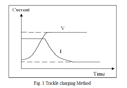 |
| In Trickle charging method the self discharged battery is continuously charged at constant current. Initially the constant charging current is high and as reach to the predetermined set point voltage the current gradually decreases with respect to time and then after the battery charges to the constant voltage, shown in fig.1. This type of charging process can farther be improved by using Fuzzy Logic Charging Algorithm. A precaution is to be taken to prevent the reverse flow of current in PV system in case of full charging of battery. The battery charging is up to 70% to 80% in not critical, but the final phase of charging of 20 % to 30% requires more precaution thereby needing a specially designed battery charging algorithm. This complexity can be avoided by using the implementation of Embedded Fuzzy Logic. |
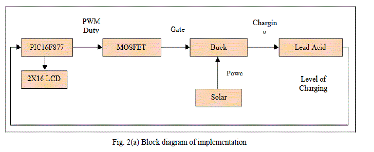
| When charging of the battery reaches to 100%, it has to disconnect the solar panel from the battery. The PIC microcontroller unit can be programmed to read the charging voltage and current of the battery according to Fuzzy rule base system and to thereon determine the PWM duty cycle. DC to DC buck controls the flow of current into the battery. The block diagram implementation is shown in fig. 2(a). Fuzzy Logic is the logic that can handle the imprecise data in precisely manner. The process of battery charging can be encoded in a rule base without requiring mathematical equations. The Fuzzy Logic is decision making logic and generates output smoothly. In the present Fuzzy Logic is implemented for final phase of battery charging as it is critical in terms of power consumption and battery life. The Embedded Fuzzy is a concept of single chip solution of control system based on data and knowledge representation using Fuzzy sets and Fuzzy rules. The process of Embedded Fuzzy involves the development of Fuzzy program into micro„CâÃâ¬ÃŸ software and uploading into the target microcontroller. |
 |
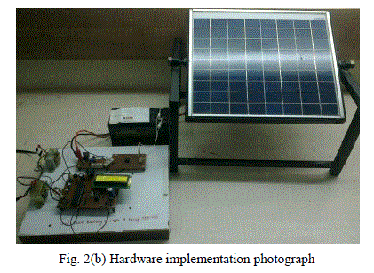
| The hardware implementation photograph is shown in figure 2(b). |
 |
| The block diagram of circuit implementation built around PIC microcontroller is shown in Fig. 3. The Embedded Fuzzy programmed chip (PIC Microcontroller) applies the Fuzzy rules to the battery conditions and computes the PWM duty cycle for the pulse that appears at RC2 pin of PIC and goes to the isolator. Output of isolator is connected to gate of the MOSFET. The power generated by PV is given to battery through buck converter. The charging rate of the battery depends on the Fuzzy PWM of the controller. The LCD 2x16 display unit displays the present current and voltage of the battery. |
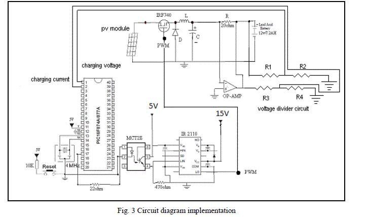 |
| A PV module is connected to the circuit and battery act as a load. The buck converter is suitable for use when the solar module voltage is high and the battery voltage is low. The real time current and voltage signal are given to Fuzzy controller (PIC) chip. The interface circuits are used to lead the battery voltage and current signals to the microcontroller. PWM drives the DC/DC buck converter, according to the Embedded Fuzzy Charging Algorithm. |
FUZZY LOGIC |
| The Fuzzy Logic Controller goes through three steps: Fuzzification, Fuzzy Inference and Defuzzification. |
| A. Fuzzification |
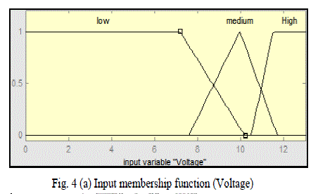
| 1) Fuzzification of Voltage-Signal: The range of Voltage-signal is partitioned into three regions with triangular and trapezoidal membership functions labelled as: Low, Medium and High over Universe of Discourse (UoD) of 0 to 13 V as shown in fig. 4(a). |
 |
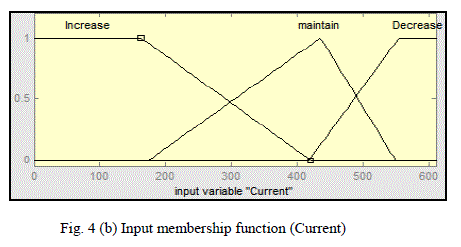
| 2) Fuzzification of Current-Signal: The second input parameter is Current signal. The range of Current-signal is partitioned into three regions with triangular and trapezoidal membership functions labelled as: Increase Maintain and Decrease over UoD of 0 to 600 mA as shown in fig. 4(b). |
 |
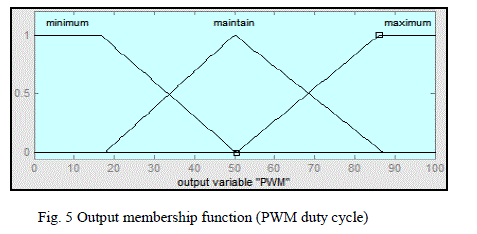
| 3) Fuzzification of PWM Duty cycle-Signal: Defuzzification converts membership functions into Crisp value for PWM signal. Three triangular partitions are labelled as Low, Medium and High over UoD of 0 to100 counts as shown in fig. 5. |
 |
| B. Fuzzy Inference System |
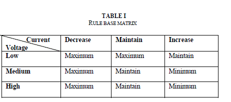
| The Fuzzy Inference forms a key part of Fuzzy Logic Control. The Fuzzy IF-THEN rule base matrix is in Table 1. |
 |
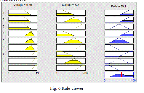
| The Fuzzy Inference based on MamdaniâÃâ¬ÃŸs scheme is shown in fig.6 for present voltage of 9.36V, current of 334mA thereby suggesting a PWM of 59.1%. |
 |
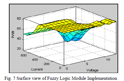
| The FIS is DISO (Dual Input Single Output) and its three dimensional view shown in fig. 7. |
 |
RESULT AND CONCLUSION |
| The battery charging below 70% in not critical, but latter part of charging needs special attention to ensure longer life of battery. |
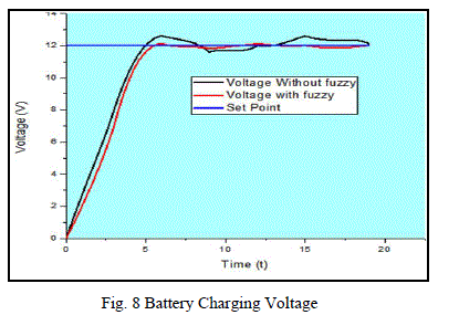 |
| The charging based on Fuzzy Logic Charging Algorithm is quite smooth as compared to non-fuzzy charging as depicted in fig.8. In full sunlight the battery charging time is about 4 to 5 hours. The response of the Embedded Fuzzy being smooth it improves the performance of battery charging. With further tuning of fuzzy sets and fuzzy rules the process of battery charging can be more and more power efficient. |
References |
|