ISSN ONLINE(2278-8875) PRINT (2320-3765)
ISSN ONLINE(2278-8875) PRINT (2320-3765)
Vijayalakshmi V1 and Karthikeyan K. B2
|
| Related article at Pubmed, Scholar Google |
Visit for more related articles at International Journal of Advanced Research in Electrical, Electronics and Instrumentation Engineering
Robotics is an ever growing field with applications in defense, industrial and consumer markets. A proper control is a necessity for accomplishing simple and complex tasks from painting cars to lifting victims out of rubble. Most of the manipulators use DC motors, whose maintenance cost and the losses are very high; this is the main reason for changing the option whenever possible with its ac counterpart. A major consideration in case of robotic arm is reducing its cost without compensating its robustness. The proposed system employs an induction motor and servo motors for developing a 3 DOF arm. Many applications are dominated by dc motor due to the fact that an induction motor drive employing constant v/f control cannot satisfactorily give the required output. By employing vector control, a decoupled closed loop control of torque and flux, similar to that of a dc motor can be achieved. It also enhances the dynamic response of the induction motor and further adds to precise tracking of parameter variations. A gear reduction mechanism is provided to achieve low speed and accuracy in position control. Decentralized control employed here not only makes the design easy but also the implementation difficulties are reduced. The system employing FOC of induction motor with space vector pwm was successfully simulated in Matlab and the results were verified. The proposed system shows effective response to even minor variations in speed and load parameters and is more efficient compared to the available system
Keywords |
| Induction motor; Vector control; Space vector PWM; Position control. |
INTRODUCTION |
| An industrial robot is defined by ISO 8373 as an automatically controlled, reprogrammable, multipurpose manipulator programmable in three or more axes. The field of robotics may be more practically defined as the study, design and use of robot systems for manufacturing. Most of the manipulator employs DC motor, making the maintenance very expensive. This is one of the main reasons for replacing these motors with its ac counterpart whenever possible. But many applications are dominated by DC motors due to the fact that the ac induction motor (ACIM) cannot satisfactorily operate with constant Volt-Hertz (V/f) scheme.[1] Applications with slowly changing loads can be effectively controlled using v/f scheme, but is less effective for applications that need fast dynamic response. Fast dynamic response can be realized without high current transients if both torque and flux can be controlled in closed loop manner. To overcome this problem, vector control is being used for past years [1]. |
| Vector control of induction motor unlike volt-hertz method not only controls the frequency and amplitude of the motor drive voltage but control the phase of the motor drive voltage in addition to the above [1],[3],[9]. The rotor current information is collected from the rotor flux vector which in turn depends on the three phase stator phasor. The dynamic performance of the drives becomes similar to that of its dc counter part by employing vector control. The main principle behind the vector control is the decoupled control of torque and flux producing component of stator current, which will be discussed in detail in the following sections. It aims to effectively control the motor torque and flux so as to force the motor to track the command trajectory accurately regardless of the variation in machine and load parameters or any other disturbances caused to the system. Today field oriented controlled drives have become the industrial standard and are available on the market by different manufacturers with different solutions and performance. |
| This paper proposes a novel and efficient multipurpose robotic arm which meets the industrial standards and which is robust and cost effective thus finding its application in academic purpose also. The basic comparison of available methods for speed control of induction motor is discussed in this paper and a suitable control is selected among them. |
| The system employs induction motor which forms the base motor of the arm. Two servo motors form the remaining two links of the arm. The control of induction motor is selected to be the industrial standard, which is the vector control or field oriented control. The paper is organized as follows: the familiarization of the proposed system and its block diagram, followed by a comparison of available system, a brief introduction to vector control followed by simulation results, hardware and conclusion. |
THE PROPOSED SYSTEM |
| An easy way to comply with the conference paper formatting requirements is to use this document as a template and simply type your text into it. |
| A. Block Diagram of Proposed System |
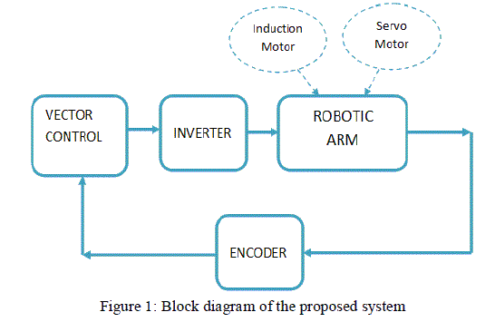 |
| The proposed system is a three link robotic arm which comprises of an induction motor and servo motors. An optical encoder is used for the positioning of arm along with positioning program in the dsPIC [9]. The rotor position or speed information is feed to the dsPIC which performs the vector control. The induction motor is used as the base motor which is otherwise called as the workhorse of motion industry due to its various advantages such as simplicity, ruggedness, high reliability, and lower cost. Another factor for choosing the ACIM is it could deal with the remaining load that’s going to come on the arm. The motor used here is provided with a gear reduction mechanism for accurate positioning and low speed operation. |
| The second motor used is a servo motor which is relatively easier to control. The servo forms the second and third link. A typical servo consists of a small electric motor driving a train of reduction gears. In a servo unit, there is a DC motor, a gear assembly, a position-sensing device, a control circuit. The control circuitry along with the potentiometer makes the servo to rotate according to our wishes. |
| The preferred control of induction motor in this paper is vector control because of its numerous advantages over other control methods of induction motor. The switching pulses generated after the vector control are then fed to the three phase inverter. The three phase inverter feeds the induction motor stator. By controlling the inverter switching the magnitude and phase of the stator current can be controlled. By controlling this it is possible to align the rotor flux vector, which forms the core of vector control. The optical encoder is designed to efficiently and accurately move the motor shaft to the desired position. The base motor, which is the induction motor, forms a revolute joint. The main focus of this paper is on the control and positioning of the base motor. The commonly employed control methods for induction motor will be compared in the next section. |
INDUCTION MOTOR PRINCIPLE AND CONTROL STRATEGY |
| A three phase induction motor is the one where on giving a three phase supply a rotating magnetic field is developed in the motor due to the nature of supply. An electromagnetic force (EMF) is induced in the rotor due to the alternating nature of supply. Hence the name induction motor. Thus there are two sets of electromagnets formed in the motor, one in the stator and the other in the rotor. The interaction between these causes development of torque and the motor starts rotating in the direction of the resultant torque. |
| Various control technique are implemented for induction motor by the modern day variable frequency drives (VFD) and they can be broadly classified as [3],[5],[8]: |
| • Scalar control |
| • Direct torque control |
| • Vector control |
| A. Scalar control |
| In this type of control, the V/f ratio is maintained constant so as to give constant flux over the entire region and to achieve constant torque. Only the magnitude of voltage and frequency is controlled here, hence the name “scalar control”. The scalar control is generally open loop control without any feedback. Here the motor is fed with a PWM fed inverter. It is the simples control and at the sametime the widespread one. However, the scalar control could not achieve required accuracy in torque and speed responses. Also, it is not applicable for applications which require a fast transient response [3],[8]. |
| B. Direct Torque Control |
| DTC is a control philosophy applied for of AC machines which exploits the torque and flux producing capabilities when fed by a voltage source inverter (VSI) .It does not require current regulator loops. It shows a similar performance to that of vector control drive. The main difference of DTC to that of FOC is that it doesn’t follow a definite switching pattern [5],[8] . It switches the inverter according to the needs of load. The heart of this technology is the adaptive model of motor. It requires information about motor parameters like, saturation coefficient, stator resistance, inductance etc. In DTC the torque and flux are directly controlled parameters with a speed reference signal from the adaptive model, hence the name Direct Torque Control or DTC. |
| The advantages of DTC are |
| • Fast response time |
| • Elimination of feedback device |
| • Reduction in mechanical failure |
| • Nearly same performance to DC machine without a feedback. |
| High torque and current ripple, and the inherent hysteresis of comparator form the main disadvantage of this scheme. The adaptive observer uses an adaptation mechanism for the speed estimation when the load torques change. |
| C. Vector Control |
| The commonly applied control method such as scalar control has its limitation. It generates oscillation in the torque produced and compromises on performance of the motor. So as to deal with all these problem superior control methods were needed. The Vector control or Field oriented control comes into play here. |
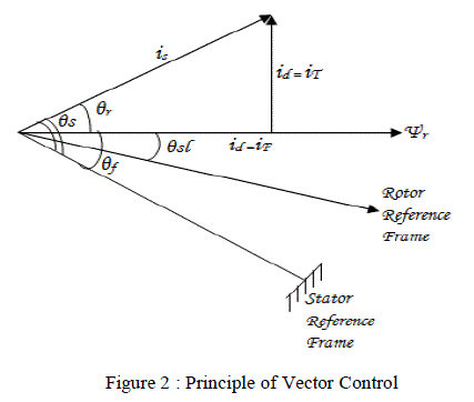
| Field Oriented Control explains the way in which the control of torque and speed are directly based on the electromagnetic state of the motor, similar to a DC motor. It facilitates the decoupling of torque and flux producing component of stator current [7],[8],[9]. With the decoupled control both of them can be controlled independently and individually. FOC was solely developed for high performance application of motor. It can operate smoothly over a wide speed range. With the decoupled control both of them can be controlled independently and individually. FOC was solely developed for high performance application of motor. It can operate smoothly over a wide speed range. It can perform quick acceleration and deceleration and can produce full torque at zero speed. |
| The other advantages of FOC are as follows: Improved torque response, Torque control at low frequencies and low speed, Dynamic speed accuracy, Reduction in size of motor, cost and power consumption, Four quadrant operation, Short-term overload capability. |
 |
| FOC for the induction motor drive is broadly classified into two types: Indirect FOC (IFOC) and Direct FOC (DFOC). The rotor flux vector in DFOC strategy is either measured by means of a flux sensor mounted in the air-gap or by using the voltage equations starting from the electrical machine parameters. In case of IFOC rotor flux vector is estimated using the field oriented control equations (current model) which require rotor speed measurement. IFOC is more commonly used because in closed-loop mode it can easily operate throughout the speed range from zero speed to highspeed field-weakening. Figure 2 shows the block diagram of indirect field oriented control. |
| Here the three phase stator currents iA, iB, iC are measured, the values in the three phase coordinates are then changed to two axis static coordinate system. The two axis system is then transformed to synchronous rotating frame, thereby making the ac quantities equivalent to dc quantities, Id and Iq. The d axis current is so aligned that it lies along the rotor flux vector Ψr, or the field axis and the q axis current is at 90 degree to the d axis current and it is perpendicular to the field axis, and is called the torque axis. Thus the current decoupling is achieved. Once the decoupling is achieved the ACIM could be controlled similar to that of a DC motor. |
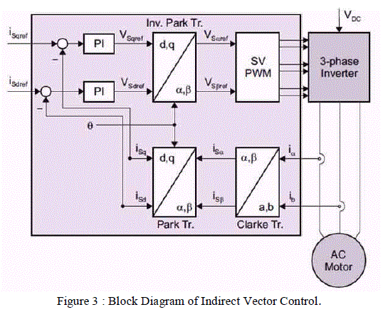 |
| Form the block diagram we can see the field current and the torque current are compared with their reference values. The error signal is then fed to PI controllers whose output will be Vdref and Vqref. They are then transformed back to the stationary reference frame using park transformation to obtain Vαref and Vβref . These voltage values are fed to the SVM block which then performs the operations to generate six PWM pulses to control the switches of the inverter. |
SIMULATION AND EXPERIMENTAL RESULTS |
| A. Induction Motor |
| The flux equation in d-q frame, |
 |
| Here Ls and Lr are the self inductance of the two phase equivalent stator and rotor windings respectively. Lm is the mutual inductance that acts between the stator and rotor equivalent windings in the d-q axis[4],[9]. |
| Now the voltage equation in d-q coordinate can be written as below. |
 |
| Here âÃÂõs is the angular speed relative to stator and ωr is the angular speed relative to rotor. Rs and Rr are the stator and rotor winding resistance respectively. p is the differential operator. The rotor is short circuited for squirrel cage induction motor so urd = urq =0. |
| The torque equation is as follows |
 |
| Where P, is the number of poles. |
| B. Vector Control Module |
| Coordinate transformation which includes Clarke and Park transformation [9]. |
| Clarke transformation converts the three axis system to the 2 axis stationary reference frame as shown below |
 |
| Converting the two phase system to three phase system is called inverse Clarke |
| Park transformation converts two axis stationary reference frames to two axis rotating reference frame, analogous to conversion from an alternating frame to a DC frame. The below equation show the same. |
 |
| C. Flux Observer Module |
| The flux observer is used to calculate the amplitude of the rotor flux and for the calculation of flux angle, θ. The amplitude of rotor flux is estimated from the following equation, the corresponding simulation block is shown in figure (). |
 |
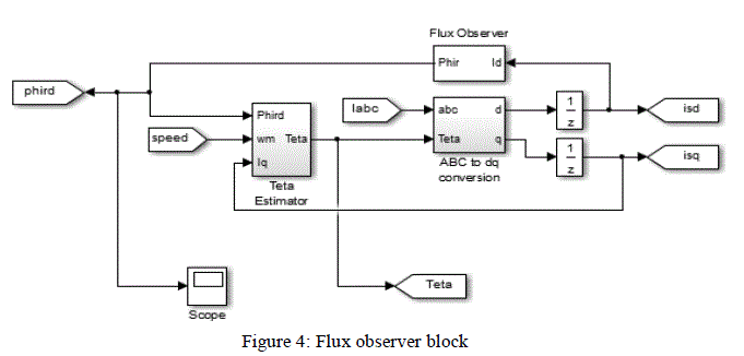 |
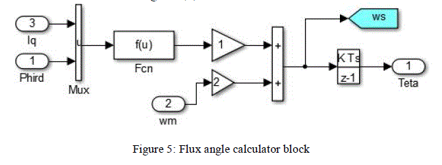
| The flux angle is calculated by integrating the sum of angular speed, ω and slip-frequency, ωs. |
 |
| The flux angle calculator block is as shown in figure (5) |
 |
| D. Space Vector Module |
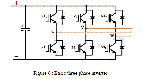
| Space vector pulse width modulation, SVPWM forms the final step of vector control which here generates pulse width modulated signals for switching of the three phase inverter that feeds the induction motor. Here we can reduce the steps to a few simple equations. The basic structure of three phase inverter is as shown below. |
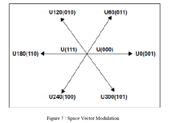
| The switches S1u,l form the upper and lower switches of leg 1, similarly for other legs also. The output of each inverter can be either connected to positive bus rail or negative bus rail depending on the switch which is turned on in the corresponding leg. There are 23= 8 possible states of output as shown in the SVM star. Out of the 8 states two states are null states where all the switches are connected either to positive rail or negative rail. |
 |
| The Space vector modulation facilitates the representation of any voltage space vector as sum of two adjacent vectors [10]. The process is to determine among the 6 sectors, in which the sector does the resultant vector lies. From this information and for the given time period T, T1 and T2 can be calculated. Now, To = T- (T1+ T2). |
 |
| By employing the SVPWM technique effective utilization of the switches are achieved. Ripple current is reduced without increasing the switching losses in the power switches. SVPWM helps in reducing the harmonic losses and also suppress the torque ripple.The SVPWM is employed here using the Matlab function block. |
SIMULATION RESULT |
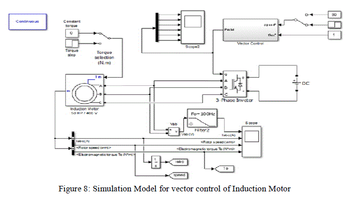
| The figure shows the simulation model for vector control of induction motor. The vector control block is created as a subsystem which incorporates the flux observer block, speed control block and the SVPWM block which were discussed before. |
 |
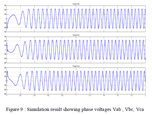
| The application here was designed for low speed hence the simulation was carried out at a reduced speed. Figure (9) shows the phase voltage waveforms for a constant speed of 80 rpm and constant torque input. |
 |
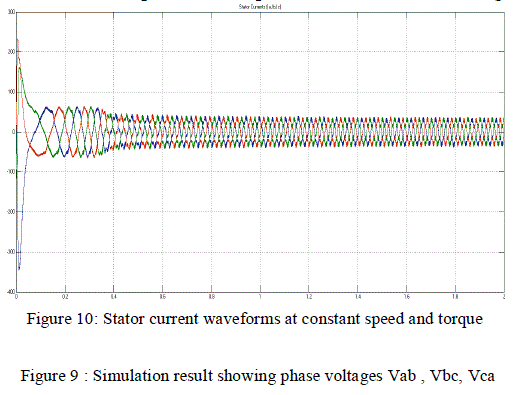
| Similarly the current waveforms for the same speed and torque condition is shown in figure (10) |
 |
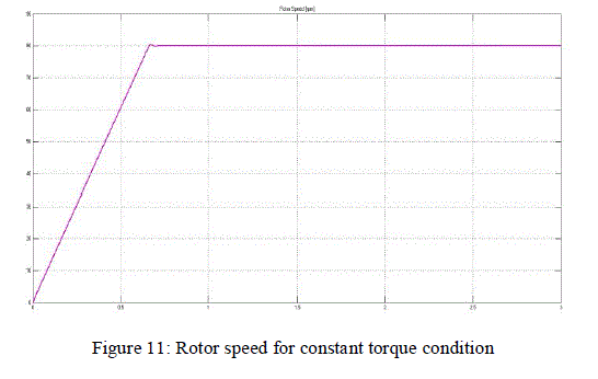
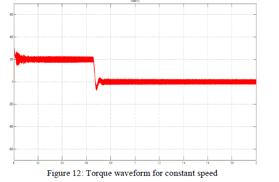
| The torque and speed waveforms are shown in figures (11) and (12) respectively. |
 |
| From the figure (12) we can observe that the maximum torque is at the starting and once the desired speed is achieved the torque gets reduced. |
 |
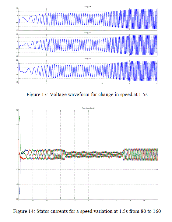
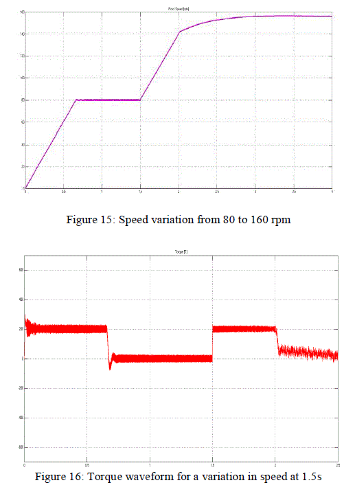
| The simulation was then carried out for a change in speed. The initial speed was given 80 rpm as earlier till 1.5s, a change in speed was introduced at 1.5s and then a variation in speed and torque were noted. The waveforms were obtained as in the following figures. |
 |
 |
| The experimental setup comprises of an induction motor with gear reduction mechanism; this forms the base motor (180W, 230V and 1350 rpm). The dsPIC 30F3011 was used to generate the switching pulses for control of induction motor according to need. A sensor was used to determine if the induction motor has reached the destination. The remaining two links of the arm is controlled using servo motors in the prototype. The signals for the servos were given using Arduino UNO board once the induction motor reaches the position. The arm was found to operate as expected. |
CONCLUSION |
| The vector control of induction motor with SVPWM technique for pulse generation was simulated using Matlab. The result shows that the speed follows the reference speed and reaches the steady state quickly. The technique is much advanced to the common v/f method. It also indicates by employing FOC we can achieve quicker dynamic responses in addition to the good static response. The hardware model further adds to the fact. The developed prototype of the robotic arm which employs an induction motor and servo motors can be used as a basic model for further research and academic purpose. |
| As a future scope the servos can be replaced with induction motor employing FOC itself for application requiring more precision. Improvement in position detection is also an area to work on. |
References |
|