Keywords
|
| Efficiency estimation, Induction motor, Air gap torque method, NAGT method, Winding health analysis |
INTRODUCTION
|
| Economic growth is desirable for developing countries, and energy is essential for economic growth. However, the relationship between economic growth and increased energy demand is not always a straight forward linear one. So the effective utilization of resource is important in the current scenario. Thus the need to conserve energy, particularly in industry and commerce is paramount. The cost of energy takes up a substantial share in the overall cost structure of the operation. Energy management calls for the optimum and effective utilization of the available resources. |
| Industry remains the biggest consumer of commercial energy and its share in the overall consumption is 49%. Induction motors are widely used in industry as essential prime movers. They are commonly used in manufacturing, transportation, petrochemical, mining, power systems and so on due to their reliability, simplicity of construction and high overload capability. These motor driven systems contribute to 70% of the total industrial electric energy consumption. Induction motors can be subjected to various types of failures due to environmental factors or machine internal factors. Motor faults show only minor symptoms but may result in higher energy consumption, lower efficiency and poorer performance. Even small faults results in large losses, high temperature which will deteriorate insulation, increased vibration level which may reduce bearing life. |
| In-service motor monitoring is relevant as the motor need not be removed from service and the down time can be minimized. This reduces the production loss as the machine is not disturbed from its service for monitoring. Not only does this reduces the financial implications associated with down time but also helps in prolonging the life span of the machine [1]. Also testing the motor in its running condition helps to obtain the motor characteristic in its real time situation which is different from the lab testing. In lab testing, the supply conditions are not polluted with degrees of harmonic distortion and unbalance which has an effect on the motor's efficiency. |
| On-line motor condition monitoring detects and monitors the operating characteristics of a motor while it is running. The major advantage of on-line condition monitoring is that the device's potential problems could be detected early before a serious deterioration or breakdown occurs [2]. The diagnosis results can clearly indicate the direction of maintenance. Also to compare the operating costs of an existing standard motor with an appropriately-sized energy efficient replacement, we need to determine operating hours, efficiency improvement values and load. Efficiency may be higher for larger motors than for smaller motors but it is still reduced when not matched to the load. Determining whether the motors are properly loaded enables to make decisions about when to replace motors and which replacements to choose. |
| Different methods are there to analyse the winding health and to determine the percentage of loading and efficiency of induction motor. But these methods are too intrusive for in-service motor monitoring, as they need either expensive speed and or torque transducers or an accurate motor equivalent circuit. Intrusion level refers to the level of disruption required in normal operation of the motor to obtain the necessary data to implement the efficiency estimation technique. Some of them require the machine to be decoupled from its load. These procedures are considered to be time consuming, manually intensive and disruptive to the machine's operation [3]. This demands the development of nonintrusive methods for monitoring and testing of industrial motors. |
WINDING HEALTH ESTIMATION
|
| Numerous methods of induction motor fault diagnosis were developed in the last decades [4] - [7]. Park’s vector approach is one of one of the simplest methods in which by monitoring the deviation of current Park’s vector the motor condition can be predicted and the presence of fault can be detected [8]. However, most of the studies have been done under the assumption that the machine operates under a symmetrical three phase supply voltage with no distortion [9]. But a small percent of voltage unbalance reflected in a higher percent of current unbalance. So when stator current is considered for fault diagnosis, erroneous decision may be made about detection of fault. I.e. under unbalanced supply voltage a healthy motor may be detected as faulty due to the large value of current unbalance. |
| A. Stator Fault Detection Method Insensitive to Supply Voltage Unbalance |
| When the induction motor is supplied with unbalanced voltage, there will be a large percent of current unbalance for a small percent of voltage unbalance. So the fault detection based on the stator current may not be correct. i.e., the current unbalance in the stator winding due to supply voltage unbalance may be mistaken as winding fault in the machine. By separating out the current unbalance due to supply voltage unbalance from the total current unbalance, the current unbalance due to winding fault can be obtained and thus the fault detection technique can be more accurate. |
 |
| Here the fault detection is based on symmetrical components of voltage and current, more particularly the negative sequence current [10]. Based on symmetrical component theory unbalanced voltage can be decomposed into symmetrical components as positive, negative and zero phase sequences (Vp, Vn and V0 respectively). Vp and Vn produces balanced currents Ip and In respectively. The total current produced by the original unbalanced voltages can be represented as the combination of the balanced currents Ip and In. Fig.2 and Fig. 3 shows the positive and negative sequence equivalent circuits of the induction motor respectively. Xm is the magnetizing reactance, Rs and Xs are the stator resistance and stator leakage reactance respectively and R’r and X’r are the rotor resistance and rotor leakage reactance referred to the stator frame respectively. In Fig.2 (a) the stator is supplied with positive sequence voltage and the motor operation is similar to that under normal balanced supply. Here the slip of the motor is‘s’ with respect to the positive sequence field of the stator. In Fig. 2(b) negative sequence voltage Vn is given to the stator and the slip of the rotor is (2-s) with respect to the negative sequence field. |
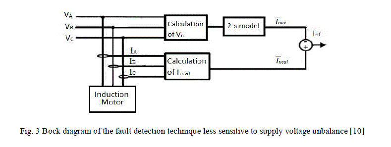
| Fig. 3 shows the block diagram of the fault detection technique which is less sensitive to supply voltage unbalance. Superposition theorem is applied in this technique [10]. VA, VB and VC are the phase voltages and IA, IB and IC are the phase currents. The total negative sequence current (due to voltage unbalance and fault) is calculated from the phase current values. (2-s) model is supplied with the negative sequence voltage Vn which is calculated from the phase voltages. The negative sequence current due to supply voltage unbalance can be obtained by solving the (2-s) model supplied with negative sequence voltage. The total negative sequence current is denoted as Incal. Inuv and Inf are the negative sequence currents due to voltage unbalance and fault respectively. All the values are in complex form. Applying superposition principle, Inuv is subtracted from Incal to obtain Inf, the negative sequence current due to fault. Inf can be taken as a reliable indicator of stator winding fault. This method of stator winding fault detection insensitive to supply voltage unbalance is adopted here for winding health analysis. |
 |
EFFICIENCY ESTIMATION METHODS
|
| An in-service motor-efficiency-estimation method can be a single basic algorithm or a combination of different basic algorithms listed in this section. The methods are commonly categorized in the literature by their intrusion levels and accuracies. The intrusion level is determined by the type of data required for each method, the cost associated with the equipment installation and data collection process, and the operation planning of the motor [11]. The accuracy is evaluated via comparison with a direct efficiency measurement, e.g., shaft torque and rotor speed. |
| A. Name Plate Method |
| The name plate method, as the name describes, makes use of the information on the machine's nameplate in order to estimate the efficiency of the motor and assumes that the efficiency of the motor is constant and equal to the nameplate value [11], [12]. The main advantage of this method is that it is considered to be the least intrusive of all the efficiency estimation methods since it merely requires access to the motor's nameplate. The errors are more here, as there may be changes in efficiency due to rewinding of motor etc. |
| B. Slip Method |
| Slip methods rely on motor speed measurement. Main advantage is the simplicity of this method. Tachometer or speed sensors can be used for measuring the speed of the motor. The motor efficiency is thus approximated using (2). |
 (2) (2) |
| However, the error comes from the fact that the slip ratio represents the percentage of load and the efficiency is not equal to the percentage of load. |
| C. Current Method |
| In standard current method, the motor efficiency is approximated using (3), assuming that the percentage of load is closely proportional to the ratio of measured current to full load current [11], [12]. |
 (3) (3) |
| In reality, the current-load curve is slightly non linear. This is considered in the new current method as (4) |
 (4) (4) |
| Again modified current method was developed in which the efficiency is the average of (3) and (4). |
| D. Equivalent Circuit Method |
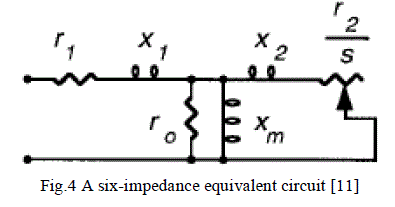
| Efficiency assessed through an equivalent circuit method is based on the impedance values of an equivalent circuit, shown in fig. 4. The six impedances are stator resistance r1, stator leakage reactance x1, magnetizing reactance xm, coreloss resistance r0, rotor leakage reactance x2, and rotor resistance r2. The slip affects the load of the equivalent circuit [11], [12]. |
 |
| The advantage of the equivalent circuit method is that the performance of a motor can be predicted at any load when the impedance values are known. On the other hand, the slip affects the load of the equivalent circuit. |
| E. Segregated Loss Method |
| The segregated loss method estimates the magnitudes of the five losses, namely, stator copper loss, rotor copper loss, core loss, stray-load loss, and friction and windage loss. The shaft output power is the input power minus the losses [11], [12]. Some of the methods in this category are quite complicated and intrusive, while others rely on empirical factors to estimate the losses. |
| F. Torque Method |
| The torque methods are considered to be the most direct of all the efficiency determination methods. The two main torque methods consist of the Shaft Torque method and the Air Gap Torque (AGT) method [13], [14]. As the most straight forward of these approaches, shaft torque method measures the shaft torque (and thus the output power) directly from the shaft, without any need to calculate losses. |
 |
| It offers the most accurate field efficiency evaluation, but is also highly intrusive. Additionally, the extremely high cost of the torque transducers makes this method not acceptable for most industrial applications. |
| The AGT method makes use of the product of air gap torque and rotor speed as the air gap mechanical power to calculate the efficiency [14], [15]. |
 |
| Where TAir gap is the air gap torque , ωr is the rotor speed, PCore is the core loss, PFW is the friction and windage loss, PSLL is the stray load loss and Pinut is the input power. The air gap torque is calculated by using instantaneous measurements of the line voltage and current waveforms to obtain a set of integral equations as given by |
 |
| Where p is number of poles, ia, ib, ic are line currents, Vab, Vca are line voltages and RS is stator resistance. So the AGT method is considered to be highly intrusive due to the measurements of stator resistance, rotor speed and no load losses [16]. |
NON – INTRUSIVE AIR GAP TORQUE METHOD
|
| The non-intrusive air gap torque (NAGT) method, as developed by [16] provides a means to obtain the efficiency of an induction machines non-intrusively by employing various estimation techniques. In particular, the stator winding resistance is estimated by incorporating a DC signal injection approach presented in [17]. The rotor speed is obtained by using a tachomter. The no load loss is calculated according to the OHME and ORMEL96 methods which assumes the losses to amount to a value of 3.5% of the rated input power [14]. The SLLs are calculated according to a fixed allowance, as depicted in the IEEE Std 112, which suggest a fixed value of 1.8% of rated output power for machines rated between 1-90kW [18]. |
| A. Stator Winding Resistance Estimation |
| The stator winding resistance estimation technique is based on the DC signal injection technique proposed in [17]. This technique has high accuracy and ease of implementation. The technique is based upon the asymmetrical resistance created by the ‘on’-‘off’ switching of a MOSFET connected in parallel to an external resistor (Rext). The DC voltage and current components associated with this switching are used to calculate the stator winding resistance. This topology is simple to install and does not require extensive signal processing. |
| B. Loss Estimation |
| The no load losses consist of the friction, windage and the core loss, and are considered to be constant and load independent. The combined friction, windage and core losses are estimated empirically by assuming a fixed value of 3.5% of the machine’s rated input power [14]. This fixed assumption provides a quick and simple means of no load loss estimation that avoids the highly intrusive no load test. The stray load loss, at rated load, is determined according to an assigned allowance as indicated in the IEC Std 34-2-1 [19] and can be calculated using (8). |
 |
| Where P1 is the input power and P2 is the rated output power. This suggests that the SLLs are not load dependent which is an unrealistic assumption, since it is well known that SLLs are load dependant. This prompts the necessity for improving the manner in which the SLLs are estimated such that they can be more realistically represented. |
MODIFIED NAGT METHOD
|
| The NAGT method of efficiency estimation is modified by improving the stray loss calculation in NAGT method. A linear regression technique similar to that of the IEC Std 34-2-1 is applied [20]. This process involves expressing the stray load loss as a function of the square of the torque for each load. |
| PSLL=AT2 (9) |
| Since the empirically estimated stray load loss is obtained at rated conditions from (8), a straight line passing through this point and the origin gives the improved values for stray load loss estimation. ‘A’ is called the co-relation factor and it can be defined for each machine according to its rating. The improved stray loss is load dependant and follows the same trend as the IEC Std 34-2-1. The improved values reflect a more realistic trend than the original estimated values. |
SIMULATION STUDIES
|
| A three phase squirrel cage induction motor is modelled in Matlab with the following parameters: 1HP, 415V, 1480Rpm, 50Hz and 4Pole. Also, Stator resistance R1 = 12.35Ω, Stator inductance (Lls) = 0.04071H, Rotor resistance (R2) = 6.991Ω, Rotor inductance (Llr) = 0.04071H, Magnetizing inductance = 0.54008H and Moment of inertia (J) = 0.010Kgm2. |
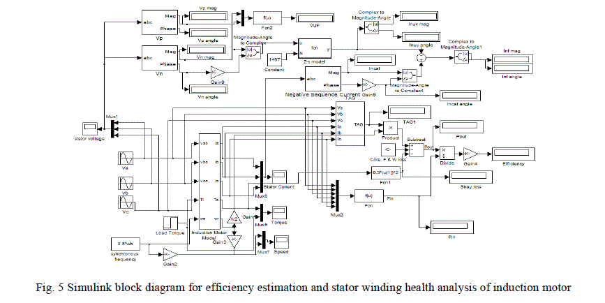 |
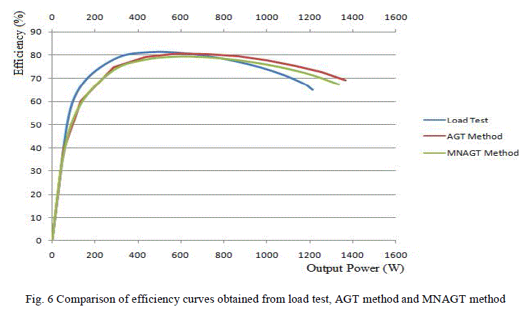
| Simulink block diagram for efficiency estimation and stator winding health analysis of induction motor is shown in fig.5. Efficiency is estimated for different loads and the efficiency curve is compared with the efficiency curve obtained from the load test. It is found that the modified NAGT (MNAGT) method is more accurate than the AGT method where the stray loss is taken as constant value according to the IEEE standard. Efficiency curve obtained from MNAGT method is more compatible with the efficiency curve obtained from load test, especially at high loads. The fault indicator showed a negligible value (0.0529 A) indicating that the motor is healthy. Simulation of the dc signal injection method of resistance estimation was done and the stator winding resistance was obtained as 12.35Ω, which is the same value as obtained from no load test of the motor. |
 |
EXPERIMENTAL SETUP AND HARDWARE
|
| The experiment is performed in a 1 HP, 415 V, 1.8 A, 50 Hz, four-pole, squirrel-cage induction motor. The block diagram for the online monitoring and efficiency estimation is given below in fig. 6. The measured variables are the supply voltages and the line currents of the motor. Stator voltages are stepped down using potential transformer and the currents are stepped down using current transformer. The voltages and current are interfaced to the computer using DAQ. |
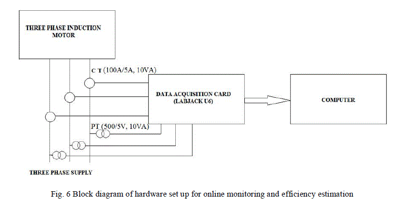 |
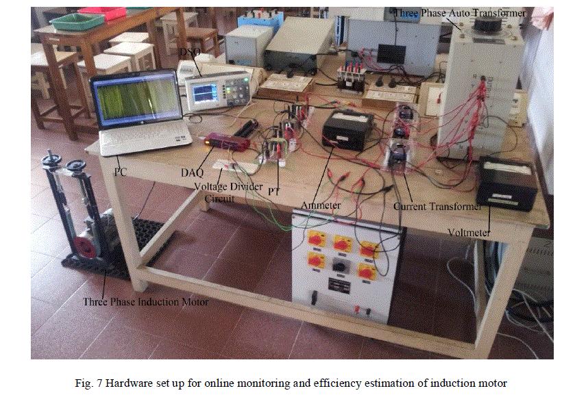
| The set up for the online monitoring and efficiency estimation is given below in fig. 7.The stator voltages are stepped down using a potential transformer with ratio 500/5 and is fed to Labjack U6 for interfacing the voltage with the computer. The stator currents are stepped down using a current transformer with ratio 100/5 and are fed to Labjack U6 through a voltage divider circuit. |
 |
| The parameters taken for analysis are phase voltage (Va), phase current (Ia), air gap torque (TAG), Speed (N), stray load loss (PSLL), Output Power (Pout), input power (Pin), Efficiency (η). Inf is the fault indicating negative sequence current. Inf has an average value of 0.0529 A, which is almost negligible. This indicates that the motor winding is healthy. Fig. 8 gives a comparison of the efficiency curves obtained from load test and MNAGT method. |
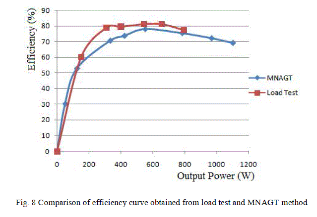 |
| It was found that they have almost similar shape. So the MNAGT method can be considered as a reliable method for efficiency estimation. The MNAGT method indicates that the motor has maximum efficiency (77.8 %) at 73.33 % loading. The motor has comparatively less efficiency at under loaded and over loaded conditions. |
CONCLUSION
|
| The efficiency estimation and condition monitoring are the major parts in the energy management of the induction motors. The NAGT torque method can be used to determine the efficiency of an induction machine while it is in operation. This method is based on the air gap torque method and it combines various non-intrusive methods to estimate the parameters that are traditionally measured in a highly intrusive manner. This includes the stator winding resistance, rotor speed, no load and stray load losses. The accuracy of the NAGT method can be modified by incorporating a modified SLLs estimation technique which reflects the SLLs more realistically. The more reliable method for practical implementation of fault detection is the symmetrical component method, more precisely the negative sequence current method. But the negative sequence current is affected by the supply voltage unbalance. So in order to eliminate the component due to supply voltage unbalance a (2-s) model of induction motor based on negative sequence equivalent circuit is introduced. The simulated results show that the reliability of the method. Experiment is done on a 1 HP squirrel cage induction motor and the results are experimentally validated. Also a hardware setup is developed for on-line efficiency estimation and condition monitoring of induction motor. |
References
|
- H. Jingtao, “Motor Energy Management Based on Non Intrusive Monitoring Technology And Wireless Sensor Networks”, EnergyManagement, pp.57-76, 2008.
- J Y. Han and Y. H. Song, “Condition Monitoring Techniques for Electrical Equipment-a Literature Survey”, IEEE Transactions onPower Delivery, vol.18, no. 1 , January 2003.
- Dona Sebastian, Manjusha V. A, Robins Anto and Victor Jose, “Non - Intrusive Testing and Energy Management of Induction Motors”,International Conference on Green Technologies (ICGT), pp.228-333, Trivandrum, 2012.
- S. Nandi, H. A. Toliyat, and X. Li, “Condition Monitoring and Fault Diagnosis of Electrical Motors - A Review”, IEEE Transactions onEnergy Conversion, vol. 20, no. 4, pp.719-729, 2005.
- J.L. Kohler, J. Sottile, F.C. Trutt, “Condition Monitoring of Stator Windings Ininduction Motors: Part I Experimental Investigation of theEffective Negative Sequence Impedance Detector”, IEEE Transactions on Industry Applications, vol. 38, no. 5, pp.1447-53, 2002.
- M.A. Cash, T.G. Habetler, G.B. Kliman, “Insulation failure prediction in AC machines using line-neutral voltages”, IEEE Transactions onIndustry Applications, vol. 34, no. 6, pp.1234-39, 1998.
- I.B.A, Tnani S, “On-line detection of stator and rotor faults occurring in induction machine diagnosis by parameters estimation", IEEETransactions on Industry Applications, 2011.
- S.M. Shashidhara, Dr.P.S. Raju, “Stator Winding Fault Diagnosis of Three-Phase Induction Motor by Parks Vector Approach”, InternationalJournal of Advanced Research in Electrical, Electronics and Instrumentation Engineering, vol. 2, no. 7, July 2013.
- I. Albizu, I. Zamora, A. J. Mazon, A. Tapia, “Techniques for On-Line Diagnosis of Stator Shorted Turns in Induction Motors”,Electric Power Components and Systems, vol. 34, no. 1, pp.97-114, 2006.
- Anju Jacob, Victor Jose and Dona Sebastian, “Stator Fault Detection in Induction Motor Under Unbalanced Supply Voltage”,International Conference on Magnetics, Machines & Drives (AICERA-2014 iCMMD), pp, 1-6, July 2014.
- Bin Lu, Thomas G. Habetler, Ronald G. Harley, A Survey of Efficiency Estimation Methods for In-Service Induction Motors, IEEETransactions on Industry Applications, Vol. 42, No. 4, July/August 2006.
- J.S Hsu, J.D Kueck, M.Olszewski, D.A Casada, P.J Otaduy, L.M Tolbert, “Comparision of Induction Motor Field Efficiency EvaluationMethods”, IEEE Trans. on Industry Applications, vol. 34, no. 1, pp. 117-125, January/February 1998.
- ArbiGharakhaniSiraki, PragasenPillay, “An In Situ Efficiency Estimation Technique for Induction Machines Working With UnbalancedSupplies”, IEEE Transactions on Energy Conversion, Vol. 27, No. 1, March 2012.
- J.D Kueck, M. Olszewski, D.A Casada, J.Hsu, P.J Otaduy, L.M. Tolbert, “Assessment of Methods for Estimating Motor Efficiency and LoadUnder Field Conditions”, Oak Ridge National Laboratory, 1996.
- J.S Hsu, P.L Sorenson, “ Field Assessment of Induction Motor Efficiency through Air-Gap Torque”, Oak Ridge National Laboratory,Tennessee, 1995.
- B. Lu, T. Habetler, R. Harley, “A Nonintrusive and In-service Motor Efficiency Estimation Method Using Air-Gap Torque WithConsiderations of Condition Monitoring”, IEEE Trans. Industry Applications, vol. 44, no. 6, pp. 1666-1674, November/ December 2008.
- S.B Lee, T.G Habetler, “An Online Stator Winding Resistance Estimation Technique for Temperature Monitoring of Line-connectedInduction Machines”, IEEE Transactions on Industry Application, vol. 39, no. 3, pp. 685-694, May/June 2003.
- IEEE Standard 112, IEEE Standard Test Procedure for Polyphase Induction Motors and Generators, 2004.
- IEC 60034-2-1, Rotating Electrical Machines-Part 2-1, 2007, Standard method for determining losses and efficiency from tests (excludingmachines for raction vehicles).
- B. Herndler, Dr P. Barendse and Dr M.A. Khan, Considerations for Improving the Non-Intrusive Efficiency Estimation of Induction MachinesUsing the Air Gap Torque Method, IEEE International Electric Machines and Drives Conference (IEMDC), 2011.
|