Renewable energy, such as wind, solar energy, is desirable for power generation due to their unlimited existence and environmental friendly nature. This paper deals with system integration and fuzzy logic based controller design for power management of a grid connected Hybrid renewable energy source (HRES). The hybrid system is the combination of photovoltaic (PV) array, wind turbine, and battery storage via a common current source interface multiple-input dc-dc converter. This converter is used to integrate the renewable energy sources to the utility grid. A two- level control system is implemented, comprising a Fuzzy logic controller, which ensures the power management between intermittent RE generation, energy storage, and grid, as well as local controllers for the photovoltaic, wind unit. Simulations are performed in MATLAB/Simulink.
Keywords |
| Renewable source, Fuzzy logic controller, power management, Grid. |
INTRODUCTION |
| Renewable energy (RE) sources will become an increasingly important part of power generation as the reserves of
fossil fuels get closer to depletion. Among available RE technologies, wind and solar energy sources are the most
promising options, as they are omnipresent, freely available, and environmentally friendly. Although these technologies
are improving in various aspects, the drawbacks associated with them, such as their intermittent nature and high capital
cost, remain the main obstacles to their utilization. Hybrid power system with energy storage can enhance system
reliability, power availability, quality, and operational efficiency. |
| Several hybrid wind/PV power systems with Maximum Power Point Tracking (MPPT) control have been proposed
earlier [5]. They used a separate DC/DC buck and buck- boost converter connected in fusion in the rectifier stage to
perform the MPPT control for each of the renewable energy power sources. These systems have a problem that, due to
the environmental factors influencing the wind turbine generator, high frequency current harmonics are injected into it.
Buck and buck-boost converters do not have the capability to eliminate these harmonics. So the system requires passive
input filters to remove it, making the system more bulky and expensive [6]. This paper uses multi-input DC-DC
converter to incorporate both wind and solar energy sources together using a combination of Cuk and SEPIC
converters, so that if one of them is unavailable, then the other source can compensate for it. The Cuk-SEPIC fused
converters have the capability to eliminate the HF current harmonics in the wind generator. This eliminates the need of
passive input filters in the system and also step-up or step-down the input voltage [11]. |
| Dynamic interaction between the load demand and the renewable energy source can lead to critical problems of
stability and power quality. Therefore, managing the flow of energy throughout the hybrid system is essential to
increase the operating life of the membrane and to ensure the continuous energy flow. The increasing number of
renewable energy sources and distributed generators requires new strategies for their operations in order to maintain the
energy balance between the renewable sources and utility grid or micro-grid [12]. |
| This paper presents the modelling of HRES and investigates the energy management optimization for a battery, grid
and HRES. A new converter topology for hybridizing the wind and solar energy sources has been proposed, it eliminate
the requirement of MPPT for each source. The average output voltage produced by the system will be the sum of the inputs of these two systems. Two level control strategies implement which are Fuzzy logic controller for energy
management, and local PV and Wind controller for best performance. |
| A. Literature review |
| In the literature, there are a few studies related to energy management of hybrid power system. Among them, Wang
and Nehrir [4], proposed a power management strategy for an ac-linked hybrid wind/PV/FC energy system. Ahmed et
al. [5], presented a power management strategy which studied power fluctuations in a hybrid PV/wind turbine/FC
power system. Onar et al. [6], proposed a power management strategy algorithm which dealt with a hybrid PV/wind/FC
power system containing an ultra capacitor bank. However, all of the early mentioned methods have used conventional
approaches for controlling hybrid power systems, such as linear PI controller which has afterwards been proven its
instability in handling various changes in weather conditions [9]. Lei Zhang et al [10] present the two scale dynamic
programming for power management which has the drawback of large time consuming and not adaptive for change of
inputs. This resulted in developing other approaches led to more robust algorithms with ability to handle various
changes dynamically without any major problems by establishing new management criteria depending upon
informational data and the environmental changes. |
| This paper uses Fuzzy logic controller for power management among battery and grid. Fuzzy logic controller does
not require complex mathematical models as used in classic control and it has been demonstrated that they are suitable
and well performing in real-time applications. |
PROPOSED ARCHITECTURE |
| Fig. 1 shows the overall architecture of the proposed wind/PV resources with grid. The main sources are Wind and
PV which are combined by multi-input CUK & SEPIC converter with DC sources. This converter is more effective for
maximum power point (MPP) tracking in PV modules and for the input current control method used in this grid. |
| Energy storage system (ESS) like Battery is also connected to the main dc bus in order to overcome the intermittent
properties of renewable energy sources and to support local power production in an islanded mode particularly during
blackouts or natural disasters. Fuzzy logic controller degied energy flow to the grid and charge control. |
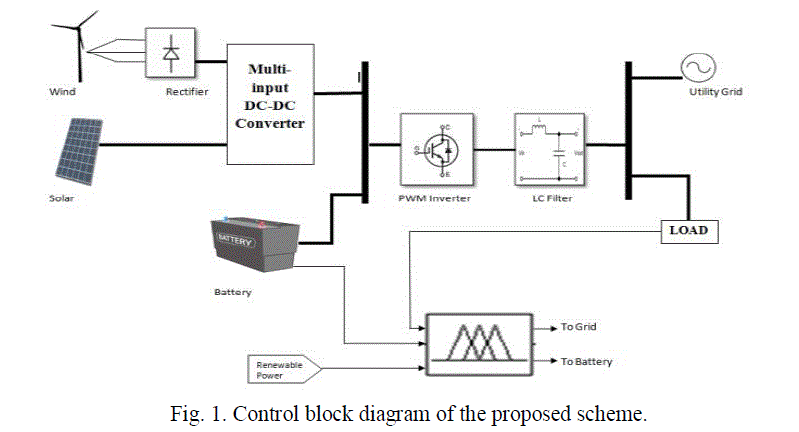 |
| DC voltage is converted into AC voltage by the PWM inverter and then fed to the local AC loads whose voltage is
240Vrms. Three phase utility grid is considered for this analysis which has voltage level of 440V, which is also tied to
the three phase 230/440V transformer. LC filter used to reduce the harmonics presented in inverter voltage. |
MODELING OF COMPONENT |
| A. PV Model |
| Photovoltaic (PV) cells are made of, semiconducting materials that can convert incident radiation in the solar
spectrum to electric currents. PV cells are most commonly made of silicon, and come in two varieties, crystalline and
thin-film type. When a photon is absorbed by a semiconducting material, it increases the energy of a valence band
electron, thrusting it into the conduction band. This occurs when the energy of incident photons is higher than the band
gap energy. The conducting band electron then produces a current that moves through the semiconducting material [3]. |
 |
| The PV cell output voltage is a function of the photocurrent that mainly determined by load current depending
on the solar irradiation level during the operation (1). |
 |
| Where the symbols are defined as follows: |
| e: electron charge (1.602 × 10⁻¹⁹ C). |
| k: Boltzmann constant (1.38 × 10⁻²³ J/oK). |
| Ic: cell output current, A. Iph: photocurrent, function of irradiation level and junction temperature (5 A). |
| I0: reverse saturation current of diode (0.0002 A). Rs: series resistance of cell (0.001 Ω). |
| Tc: reference cell operating temperature (20 °C). Vc: cell output voltage, V. |
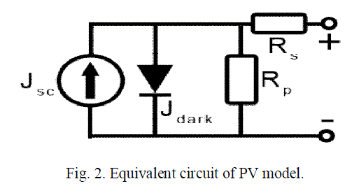
| Both k and Tc should have the same temperature unit, either Kelvin or Celsius. The solar cell can be seen as
a current generator which generates the current (density) Jsc. The dark current flows in the opposite direction and is
caused by a potential between the + and - terminals. In addition it would have two resistances; one in series (Rs) and
one in parallel (Rp). The series resistance is caused by the fact that a solar cell is not a perfect conductor. The parallel
resistance is caused by leakage of current from one terminal to the other due to poor insulation. |
| B. Wind model |
| Wind turbines convert mechanical energy produced by the wind to electrical energy. To use this electrical
energy, voltage and frequency regulation are needed. The model of a wind turbine is developed on the basis of the
steady-state power characteristics of the turbine [8]. The mechanical power produced by a wind turbine is shown in
Equation (2). |
 |
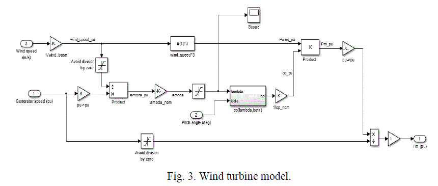 |
| The Simulink model of the studied wind turbine is shown in Figure 3.In Eq. (1), Pm is the mechanical output power
of the turbine (W), Cp is the performance coefficient of the turbine, λ is the tip speed ratio of the rotor blade tip speed to
the wind speed (in degrees), β is the blade pitch angle (in degrees), ρ is the air density (kg/m3), A is the turbine swept
area (m2), and v is the wind speed (m/s). The expression “Cp(λ, β)” is calculated by using Eqs. (3) and (4). |
 |
| Coefficients C1 through C6 are: C1 =0.5176,C2 =116,C3 =0.4,C4 =5,C5 =21, and C6 =0.0068. β is equal to 0,
but, if necessary, this value can be changed. |
| C. Multi-input converter |
| Multi-input CUK and SEPIC converters are used in this simulation. These MI CSI converters provide nearly
continuous input current waveforms due to their CSI input legs. Hence, these converters provide more operational
flexibility than an MI buck- boost converter[1] because they allow the integration of input sources that require a
relatively constant current], such as the input current control |
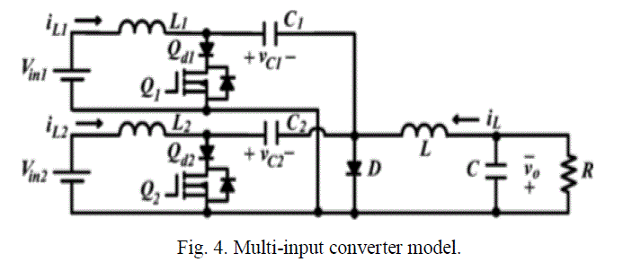 |
| An MI Ćuk converter [7] is similar to an MI SEPIC converter [7][11] except for the output voltage inversion. This
analysis focuses on the MI Ćuk converter shown in Fig. 4. |
| D. Battery model |
| The mathematical modeling of Li-Ion battery is used in the simulation. The open voltage source is calculated
with a non- linear equation based on the actual SOC of the battery as follows [13](5)-(7): |
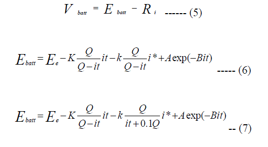 |
| where Ebatt is the no-load voltage, Eo is the battery constant voltage, K is the polarization constant, Q is the
battery capacity, it is the actual battery charge, i* is the low frequency current dynamics, A is the exponential zone
amplitude, B is the exponential zone time constant inverse (Ah)-1, Vbatt is the battery voltage, and i is the battery
current. The main feature of this battery model is that the parameters can easily be deduced from a manufacturer’s
discharge curve [13]. |
| E. The Fuzzy Logic Concept |
| Fuzzy logic arose from a desire to incorporate logical reasoning and the intuitive decision making of an expert
operator into an automated system. The aim is to make decision based on a number of learned or predefined rules,
rather than numerical calculations. Fuzzy logic incorporates rule-base structure in attempting to make decisions.
However, before the rule-base can be used, the input data should be represented in such a way as to retain meaning,
while, still allowing for manipulation. Fuzzy logic is an aggregation of rules based on the input state variables condition
with a corresponding desired output. A mechanism must exist to decide on which output or combination of the different
outputs will be used since each rule could conceivably result in a different output action. Fuzzy logic can be viewed as
an alternative form of input-output mapping. |
| The fuzzy rule representation is based on linguistic [14]. Thus, the input is a linguistic variable that
corresponds to the state variable under consideration. In fuzzy logic control, the term “linguistic variable” refers to
whatever state variables the system designer is interested. The fuzzy variable is perhaps better described as a fuzzy
linguistic qualifier. |
| Once, the linguistic and fuzzy variables have been specified, the complete inference system can be defined as
developing a FIS and applying it to a control problem involves several steps: |
| a. Fuzzification. |
| b. Fuzzy rule evaluation (fuzzy inference engine). |
| c. Defuzzification. |
FUZZY LOGIC CONTROL STRATEGIES |
| Several techniques are available for the implementation of the energy management algorithm [4][9][10].
Among them fuzzy logic technique has low power dissipation, an optimized cost, and reliable and stable. Fuzzy
systems (FS) are based on fuzzy set theory and it is a non-linear control method, which attempts to apply the expert
knowledge of an experienced user to the design of a fuzzy-based controller. |
| The energy management strategy (EMS) should determine the split power between the photovoltaic, wind
turbine, grid and battery while satisfying the load power requirement. Power demand is unpredictable in nature and
varying frequently, so load profile is unavoidable. If adding this, to the nonlinear subsystems the system becomes
complex of the structure of hybrid system. Hence, an advance fuzzy expert system according to the weather variations,
load demand and SOC is presented. Figure 5 shows the proposed fuzzy expert system. |
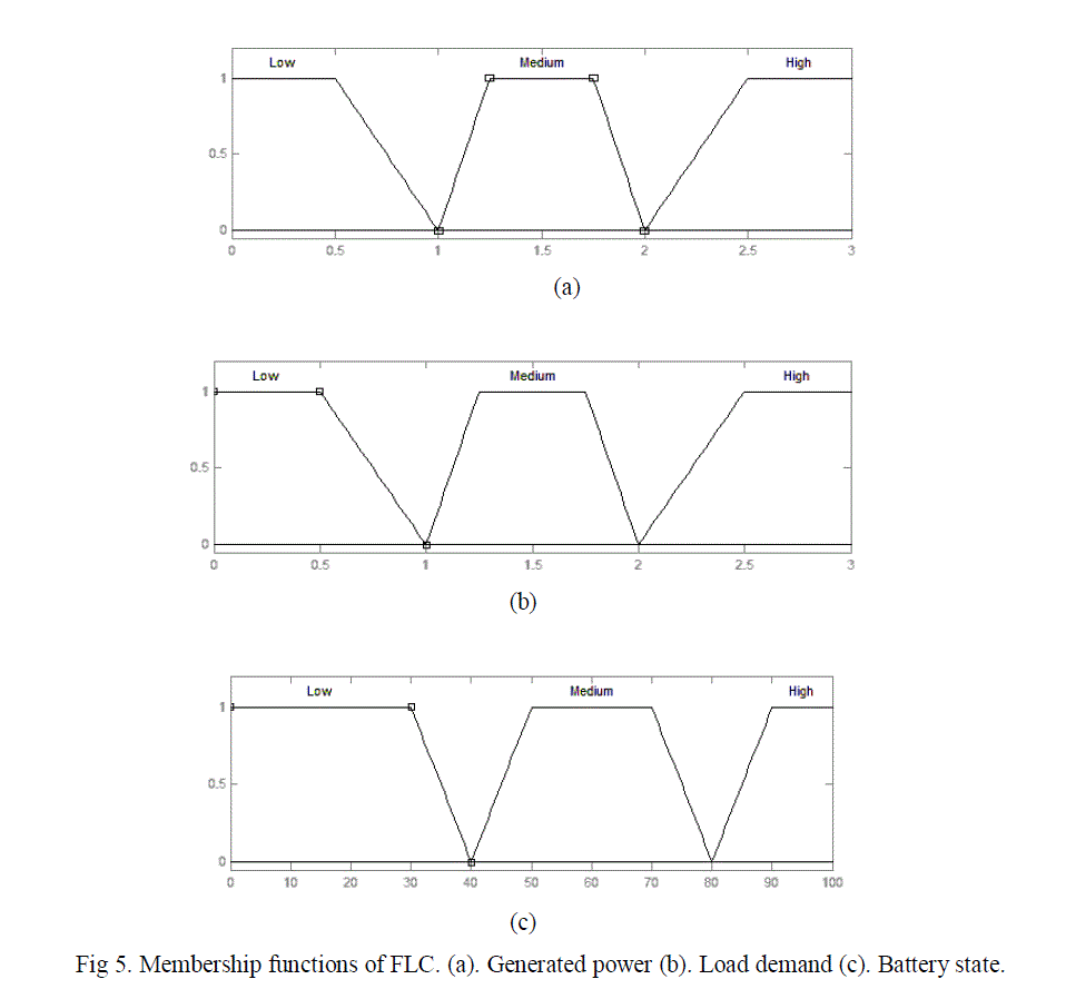 |
| When in normal operation, system power changes smoothly so that the grid operating point deviation is
minimized. The battery management system maintains the SOC at a reasonable level (40% - 80%). Also, it protects
against voltage collapse by controlling the power level required from the battery. |
| The power management system controls the reference power of the grid by splitting the power demand (PL) as a
function of the available power of the battery and the PV/Wind system (PG). |
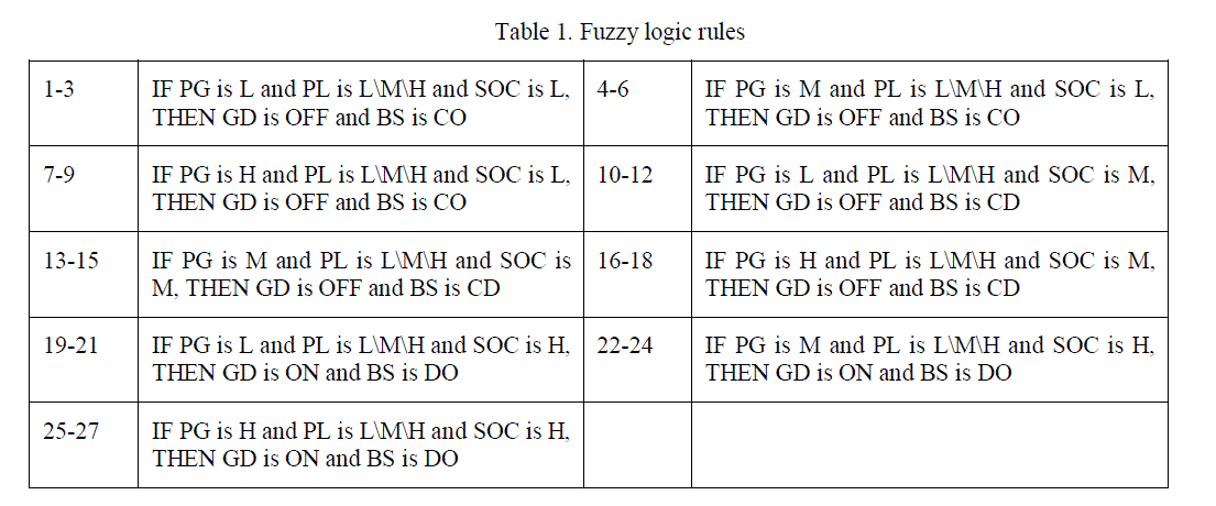 |
| The FLC relates the outputs to the inputs using a list of IF-THEN statements called rules. The if-part of the
rules describes the fuzzy set (Regions) of the input variables. In this work, the fuzzy input variables are PG, PL, and
SOC and output variables are GD, BS. The degrees of membership are evaluated to obtain the output controller, and the
then-parts of all rules are averaged and weighted by the degrees of membership. |
SIMULATION RESULTS |
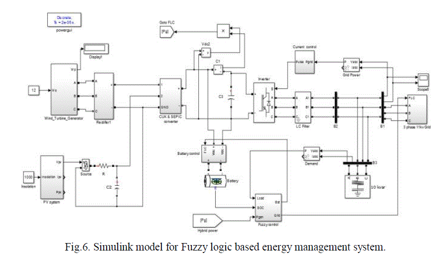
| The electrical subsystem consists of primary sources of energy unit like PV unit and wind unit, battery bank
unit act as auxiliary source of energy. Fuzzy logic is developed to control the power management between different
sources and the load. The FLC control unit designed to control the battery current, grid power flow according to the
supplement of the load with the required power. FLC has three inputs and one output. The inverter unit is used to
convert the DC generated power from renewable energy sources to feed the load with the required AC power. The
overall simulation diagram is shown in fig 6. |
 |
| A. Isolated mode |
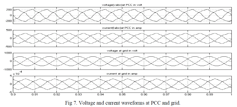
| The initial SOC of the battery storage is 50%. Hence, the SOC is medium, the low load demand is satisfied by the
RS, and the extra power will be used to charge the battery. The battery is charged/ discharge and average current flow
through it. The renewable system is isolated from grid. The Current and voltage waveforms of PCC and grid are shown
in fig 7. |
 |
| B. Grid interacted mode |
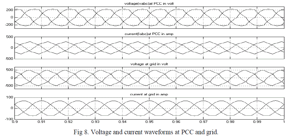
| In this case SOC of battery storage is 80%, this will indicate battery fully charged. In this mode excess energy
supply to the grid, the battery only discharge and cannot charge in this mode. The Current and voltage waveforms of
PCC and grid are shown in fig 8. |
| In above two cases the voltage at the PCC will be regulated as constant 230V AC, by controller used in inverter, and
filter circuit eliminate the harmonics present in the AC voltage. |
 |
CONCLUSION |
| The power management between PV array, wind generator, battery bank and the load was controlled using
FLC. The simulation results using FLC in MATLAB/SIMULINK showed the high performance of the proposed
system. The results showed that the PV and wind generator were capable of feeding the load with the required energy
and charge the battery with its demands during night hours. During day time high power generated from the PV
system, due to that excess power send to the utility grid after battery fully charged. FLC has three input signals which
are hybrid power, demand and state of charge. 27 rule bases, the COG and Max-Min method were used. |
References |
- B. G. Dobbs and P. L. Chapman, âÃâ¬ÃÅA multiple-input DC-DC converter topology,âÃâ¬Ã IEEE Power Electron. Lett., vol. 1, no. 1, pp. 6âÃâ¬Ãâ9, Mar. 2003.
- Chen et al., âÃâ¬ÃÅMulti-Input Inverter for Grid-Connected Hybrid PV/Wind Power SystemâÃâ¬ÃÂ, IEEE Transactions on Power Electronics, vol. 22, May 2007.
- Altas, I.H. Sharaf.A.M, âÃâ¬ÃÅA Photovoltaic Array Simulation Model for Matlab-Simulink GUI EnvironmentâÃâ¬ÃÂ, IEEE International conference onClean Electrical power, May 2007, pp 341-345.
- C. Wang and M. H. Nehrir, âÃâ¬ÃÅPower Management of a Stand-Alone Wind/PV/Fuel Cell Energy System,âÃâ¬Ã IEEE Energy Conversion, Vol. 23, No. 3,2008, pp. 957-967.
- N. A. Ahmed, M. Miyatake and A. K. Al-Othman, âÃâ¬ÃÅPower Fluctuations Suppression of Stand-Alone Hybrid Generation Combining SolarPhotovoltaic/Wind Turbine and Fuel Cell Systems,âÃâ¬Ã Energy Conversion and Management, Vol. 49, No. 10, 2008, page no 2711-2719.
- O. C. Onar, M. Uzunoglu and M. S. Alam, âÃâ¬ÃÅModeling, Control and Simulation of an Autonomous WT/PV/FC/ Ultra-Capacitor Hybrid PowerSystem,âÃâ¬Ã Journal of Power Sources, Vol. 185, No. 2, 2008, pp. 1273-1283.
- A. Kwasinski, âÃâ¬ÃÅIdentification of feasible topologies for multiple-input DC-DC converters,âÃâ¬Ã IEEE Trans. Power Electron., vol. 24, no. 3, pp. 856âÃâ¬Ãâ861, Mar. 2009.
- S. Li, T. A. Haskew, and L. Xu, âÃâ¬ÃÅConventional and novel control designs for direct driven PMSG wind turbines,âÃâ¬Ã Elect. Power Syst. Res., vol. 80,no. 3, pp. 328âÃâ¬Ãâ338, Mar. 2010.
- A. Tofighi and M. Kalantar, âÃâ¬ÃÅPower Management of PV/ Battery Hybrid Power Source via Passivity Based Control,âÃâ¬Ã Renewable Energy, Vol. 36,No. 9, 2011, pp. 2440- 2450.
- Lei Zhang, Yaoyu Li, âÃâ¬ÃÅOptimal Energy Management of Wind-Battery Hybrid Power System With Two-Scale Dynamic ProgrammingâÃâ¬ÃÂ, IEEEtransaction on sustainable energy, Volume 4, No 3, July 2013, Page No 765-773.
- TriptiSaha, Deependra Kumar Jha, âÃâ¬ÃÅFused Converter Topology for Wind-Solar Hybrid SystemsâÃâ¬ÃÂ, IEEE ,2013.
- Luis Valverde, Felipe Rosa, Carlos Bordons, âÃâ¬ÃÅDesign, Planning and Management of a Hydrogen-Based MicrogridâÃâ¬ÃÂ, IEEE transactions onindustrial informatics, vol. 9, No. 3, august 2013.
- MathWorks,âÃâ¬ÃÅDocumentation Center,âÃâ¬Ã 2012. http://www.mathworks.co.uk/help/stateflow/gs/a-look-at-t he-physical-plant.html
- L.A. Zadeh, âÃâ¬ÃÅFuzzy setsâÃâ¬ÃÂ, Information Control, Vol. 8, pp. 338-353, 1965.
|