Renewable energy sources play an important role in electrical energy generation. The drawbacks of Renewable energy sources have been overcome by the use of hybrid power generating unit. A typical hybrid renewable energy system (HRES) combines several renewable energy sources such as wind turbine (WT) and photovoltaic (PV) panels as primary energy sources and an energy storage system (ESS) based on fuel cell and battery. All of the energy sources are connected together to a central dc bus by means of power converters. This paper includes a supervisory control called hysteresis switching algorithm which determines the power that must be generated by/stored in the fuel cell and battery, taking into account the control demand by the grid, the offered power, the hydrogen reservoir point and the state-of-charge (SOC) of the battery. The proposed EMS is compared with classical EMS composed of state based supervisory control system based on states and inverter control system based on PI controller. Dynamic simulation results of the proposed EMS demonstrate the better performance than the classical EMS.
Keywords |
| Hysteresis, Energy management system, Energy storage system, Renewable power sources, Mixture
system. |
INTRODUCTION |
| A typical HRES configuration combines several renewable energy sources, such as wind turbine (WT) and
photovoltaic (PV) panels, with ESS. The renewable sources are used as primary energy sources, which are generating
whenever there is wind or solar radiation. However, because the sun irradiance and the wind speed are uncontrollable
parameters, a support energy source is needed to increase the degree of controllability and operability of the HRES.
Traditionally, this function is performed by an ESS such as battery and hydrogen system (i.e., FC, electrolyzer and
hydrogen storage tank). These ESS are considered to be an effective solution to balance the generation and demand
supporting the renewable energy deficit when necessary, and storing the primary energy excess when possible. All
renewable sources and ESS are connected together to a central dc bus by means of power converters. These converters
are designed to deliver energy from the energy sources, ensuring stable, sustainable and reliable operation. In gridconnected
mode, dc–dc and ac–dc power converters interface the renewable sources and ESS to a dc bus, while dc–ac
voltage source inverters are in charge of delivering the active and reactive power to the grid. |
| HRES presents two-level control architecture. In the highest level, the supervisory control system is responsible for
determining the reference power that must be generated by/stored in the ESS. The lowest level is in charge of
controlling the converters associated with the renewable sources and ESS, so that the energy sources work as required
by the supervisory control system. Most of the studies about HRES control architectures consider standalone operation
in isolated sites due to the advances in renewable energy technologies and power electronic converters, which are used
to convert the unregulated power generated from the renewable sources into useful power at the load end. Classical and
intelligent control techniques have been applied to the control system of stand-alone HRES. Classical control
techniques (i.e., based on state machine controllers or PI controllers) require exact mathematical model of the system
and are very sensitive to parameter variations. Intelligent control techniques such as artificial neural networks, fuzzy logic, or neuro-fuzzy are more efficient and robust than classical techniques, since they do not require an exact model
of the system and improve the dynamic behaviour of the system. |
| This paper presents a new hysteresis-based EMS for a HRES composed of renewable energies, hydrogen and battery,
and an hysteresis-based control for the three-phase inverter, which connects the HRES to grid. The main novelties of
this paper are: 1) the application of hysteresis to the supervisory control system of a grid-connected HRES in order to
determine the power that must be generated by/stored in the ESS (hydrogen and battery), taking into account the
control demand by the grid, the offered power, the hydrogen tank level and the battery SOC and 2) the application of
hysteresis to the three-phase inverter in order to properly control the power delivery to grid by using the active and
reactive power as control variables. It is organized as follows. Section II describes the grid-connected hybrid system
under study. Section III describes the classical EMS used to evaluate the performance of the Hysteresis based EMS.
Simulation results are presented in section IV. Finally, Section V establishes the conclusions derived from this work. |
GRID-CONNECTED HYBRID SYSTEM |
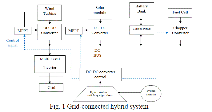
| Fig. 1 shows the grid-connected hybrid system under study in this work, which is composed of WT and PV panels
(renewable and primary energy sources) and hydrogen subsystem and battery (ESS). All of them use dc–dc power
converters in order to connect them to a central dc bus. The whole system is connected to a grid by a three-phase
inverter. In this system, the renewable sources are generating whenever there is wind or solar radiation. When possible,
renewable energy is stored in the battery and/or in the form of hydrogen by using the electrolyzer, and this stored
energy is recovered to support the renewable production when necessary. |
 |
| A dynamic model of this grid-connected hybrid system is implemented in a MATLAB/Simulink environment, as
described below. |
| A. Wind Turbine |
| The WT presents a rated power of 1.5 kW. It presents a two blade turbine coupled to a three-phase permanent magnet
synchronous generator (PMSG). This WT is represented by a model with the following subsystems: turbine and
generation system. The turbine model expresses the mechanical power extracted from the wind, which is a function of
the wind speed and the blade tip speed ratio, as defined by the actuator disk theory. The generation system is composed
of a three-phase PMSG, ac–dc converter, and dc–dc converter, which are represented by models included in Sim Power
Systems [1]. The electrical and mechanical parts of the PMSG are represented by a second order state-space model.
The ac–dc and dc–dc converters are modeled by average-value equivalent models. The dc–dc power converter, which
connects the WT to the hybrid system dc bus, is controlled by a torque reference-based maximum power point tracking
(MPPT) control in order to extract the maximum available power from the WT. This MPPT control maintains the
operating point of the WT on its maximum power coefficient for any wind speeds in the below-rated wind speed
region, modifying the duty cycle of the WT dc–dc converter, which produces a variation of its rotational speed. |
| Furthermore, the WT generation system incorporates a braking resistor at the dc bus, in which the power excess with
above nominal winds is dissipated to assure WT rated power. |
| B. PV Panels |
| The PV system presents nine 0.180-kW PV panels, with a total rating of 1.6kW.Asingle-diodemodel, which is
composed of a current source and a parallel diode (representing the ideal PV cell) with two resistances (series and
parallel resistances), is used to represent each PV panel. This model presents suitable accuracy [1], and the parameters
are easy to find in the commercial datasheets [7], which makes it perfect for the simulation of PV devices with power
converters. A dc–dc power converter controlled by a MPPT controller adapts the PV output voltage to the dc bus
voltage. The MPPT controller generates the duty cycle of the PV converter to move the PV voltage to the voltage that
corresponds to the maximum power point (MPP). In this work, the MPP voltage is defined as proportional to the PV
open-circuit voltage [11]. Thus, a fractional open-circuit voltage algorithm is used as MPPT algorithm to generate the
duty cycle of the controller due to its simplicity. |
| C. Hydrogen Subsystem |
| The hydrogen subsystem is composed of 0.48-kWPEM electrolyzer, 2280-liter hydrogen tank, and 1.2-kW PEM FC.
PEM electrolyzer and PEM FC are highly efficient units that are suitable for autonomous and distribution operation [5].
The PEM electrolyzer uses electrical energy to produce hydrogen from water. It is modeled by a resistance, in which
the power needed to produce hydrogen is consumed. Faraday’s law is used to calculate the hydrogen produced
depending on the electrical current in the resistance [4]. The hydrogen produced by the electrolyzer is stored in the
hydrogen tank. In the hydrogen tank model, the hydrogen available in the tank is obtained from the rate of incoming
and outgoing hydrogen, taking into account the ideal gas equation [2]. The PEM FC uses the hydrogen available in the
tank in order to produce electrical energy. It is modelled by a reduced model of the complete model detailed in [10]. |
| The validity of the reduced model was demonstrated in [8], where both the reduced and complete models were
compared, showing similar responses, but with a considerable reduction of the computational time for the first one.
Several control strategies for FC vehicles [2]–[5] were evaluated by using this reduced model. In this reduced model,
the FC voltage depends on the cell voltage and number of cells [1], [5]. The cell voltage is determined as a function of
the current density, temperature, and water, and hydrogen and oxygen partial pressures. The compressor, which
controls the air flow in the cathode to keep constant the oxygen excess ratio, is represented by a first-order system.
Finally, an ideal air cooler and humidifier are considered in the FC model [4]. |
| D. Batteries |
| The hybrid system uses a 14.48-kWh lead-acid battery. This type of battery is usually the least expensive storage
battery for any application, while still providing good performance and life characteristics [4]. This battery is modelled
by a conflict in series with a variable voltage source [5]. |
| E. DC–DC Converters |
| Each energy source of the hybrid system provides a variable voltage, which depends on the current demand, at different
ranges. Therefore, it uses a pulse-width modulated (PWM) dc–dc converter [6] to transfer the output power to the
central dc bus. The output voltage of the WT rectifier is higher than the dc bus voltage. Thus, the WT plus rectifier
system is connected to the dc bus by using a buck-type unidirectional converter. The connection of PV, FC, and
electrolyzer to the dc bus is performed by using boost-type unidirectional converters. The PV and FC converters
transfer power from the source to the dc bus, since both sources terminal voltages are lower than the dc bus voltage.
The electrolyzer converter transfers power from the dc bus to the electrolyzer, whose terminal voltage is higher than the
dc bus voltage. The battery uses a bidirectional converter, which allows the power flow from the battery to the dc bus
(boost-type) and vice versa (buck-type). Each dc–dc converter is modeled by using the two-quadrant chopper model
included in SimPowerSystems [9]. In this model, the chopper is represented by a simplified version of the converter
containing an average-value equivalent model. |
| F. Inverter |
| A three-phase IGBT inverter connects the dc bus of the hybrid system to grid. This inverter is represented by the model
developed in [3]. In this model, the snubber capacitor is eliminated, so that only the snubber resistance is taken into
account. Furthermore, the forward voltages of the IGBTs and diodes are considered null. The inverter is PWM to
produce the three-phase 50-Hz sinusoidal voltage. It uses hysteresis switching and controls the active and reactive
power, as will be shown below. |
CLASSICAL ENERGY MANAGEMENT SYSTEM OF THE HYBRID SYSTEM |
| Here, the classical EMS used to test the performance of the proposed Hysteresis control system is described. The
classical EMS is composed of state-based supervisory control system based on states and inverter control system based
on PI controllers. |
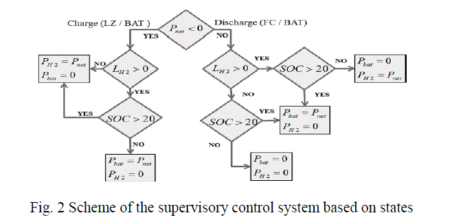 |
| The supervisory control system uses the control scheme shown in Fig. 2 in order to determine the power generated
by/stored in the hydrogen and battery, taking into account the power demanded by the grid, the available power, the
hydrogen tank level and the battery SOC. |
SIMULATION RESULTS |
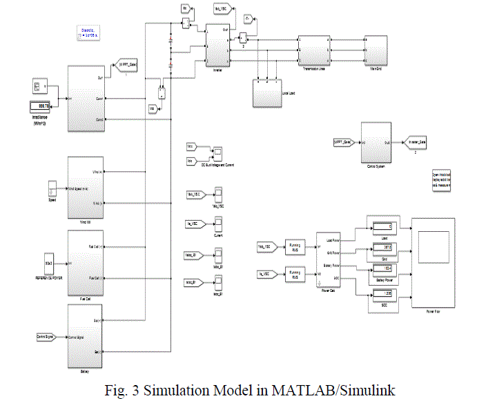 |
| Fig. 3 presents the power demanded by the network and the power of each energy source during 20 s. As mentioned
previously, the renewable sources are generating the maximum available power. During the first 10 s, the renewable
power (PV and WT power) is higher than the power demanded by the grid. In this case, the power excess is stored in
the battery and used in the electrolyzer to produce hydrogen. From the second 10 s, the power demanded by the grid
increases, and it becomes higher than the renewable power. Then, the FC and battery generate extra power to satisfy the
demanded power. |
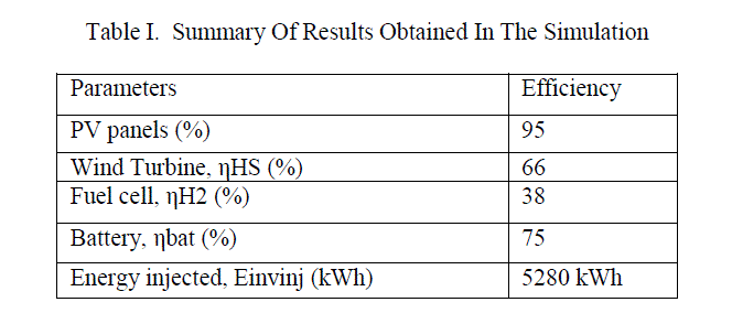
| Table I Presents the results (i.e., battery, hydrogen system, and hybrid system efficiencies and the energy injected into
grid) obtained by each control during the first simulation. Analyzing the results, it can be concluded that the Hysteresis
control achieves higher battery and hybrid system efficiencies, and it is capable of injecting more energy into grid than
the classical control. It shows in detail the dynamic behaviour of the supervisory controls and inverter control systems. |
| The implemented EMS is based on a predictive controller, which generates the FC and battery reference currents to
provide the power demanded by the tramway, meeting the battery and SC SOC constrains (i.e., keeping their SOC
between a specific range) and ordering the operation of the braking resistor, when necessary, during regenerative
braking[4]. |
 |
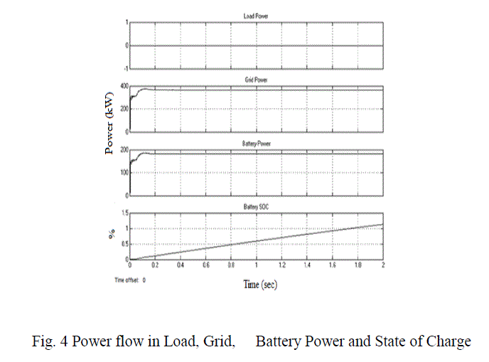
| A .Charging condition |
| Fig. 4 presents load is off. The power flow through grid and battery. Here the battery is charging mode. |
 |
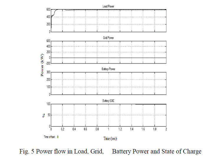
| B.Discharging situation |
| Fig. 5 presents load is on. The power flow through load only. Here the battery is discharging mode. |
 |
CONCLUSION |
| The renewable energy sources operate at the Maximum Power Point, independently of the Energy Management System
(EMS). Therefore, the EMS is responsible for managing the operation of the ESS (battery and hydrogen system), taking
into account the power demanded by the grid, the available renewable power, and the available ESS power (battery
SOC and hydrogen tank level). Once determined which ESS has to absorb/generate the power excess/deficit, the
appropriate control of the dc–dc converter associated to the battery and hydrogen system allows the ESS to achieve the
operation required by the EMS, maintaining constant the dc bus voltage. On the other hand, in coordination with the
EMS, the three phase inverter is controlled by a Hysteresis-based controller in order to regulate the active and reactive
power that the hybrid system is required to deliver with the grid. |
References |
- Chunhua Liu, Xiaodong Zhang, âÃâ¬ÃÅAn Efficient WindâÃâ¬ÃâPhotovoltaic Hybrid Generation System using Doubly Excited Permanent-Magnet Brushless MachineâÃâ¬ÃÂ, IEEE Trans. Ind. Electron., vol. 57, no. 3, pp.831-839, 2013.
- F. Kennel, D. GÃÆörges, and S. Liu, âÃâ¬ÃÅEnergy management for smart grids with electric vehicles based on hierarchical MPC,âÃâ¬Ã IEEE Trans. Ind. Inf., vol. 9, no. 3, pp.1528âÃâ¬Ãâ1537, Aug. 2013.
- F.GonzÃÆález-EspÃÆÃÂn, I. Patrao, E. Figueres, and G.GarcerÃÆá, âÃâ¬ÃÅAn adaptive digital control technique for improved performance of grid connected inverters,âÃâ¬Ã IEEE Trans.Ind. Inf., vol. 9, no. 2, pp. 708âÃâ¬Ãâ718, May 2013.
- J. P. Torreglosa, P. GarcÃÆÃÂa, L.M. FernÃÆández, and F. Jurado, âÃâ¬ÃÅPredictive control for the energy management of a fuel cell-battery-super capacitor tramway,âÃâ¬Ã IEEETrans. Ind. Inf., vol. 10, no. 1, pp. 276âÃâ¬Ãâ285, Feb. 2014.
- L. Valverde, F. Rosa, and C. Bordons, âÃâ¬ÃÅDesign, planning and management of a hydrogen-based microgrid,âÃâ¬Ã IEEE Trans. Ind. Inf., vol. 9, no. 3, pp. 1398âÃâ¬Ãâ1404,Aug. 2013.
- M. P. Kazmierkowski, M. Jasinski, and G.Wrona, âÃâ¬ÃÅDSP-based control of grid-connected power converters operating under grid distortions,âÃâ¬Ã IEEE Trans. Ind. Inf.,vol. 7, no. 2, pp. 204âÃâ¬Ãâ2011, May 2011.
- M. Singh and A. Chandra, âÃâ¬ÃÅReal-time implementation of ANFIS control for renewable interfacing inverter in 3P4W distribution network,âÃâ¬Ã IEEE Trans. Ind.Electron., vol. 60, no. 1, pp. 121âÃâ¬Ãâ128, Jan. 2013.
- P. Siano, C. Cecati, H. Yu, and J. Kolbusz, âÃâ¬ÃÅReal time operation of smart grids via FCN networks and optimal power flow,âÃâ¬Ã IEEE Trans. Ind. Inf., vol. 8, no. 4, pp.944âÃâ¬Ãâ952, Nov. 2012.
- S. Dasgupta, S. N. Mohan, S. K. Sahoo, and S. K. Panda, âÃâ¬ÃÅA plug and play operational approach for implementation of an autonomous micro- grid system,âÃâ¬Ã IEEETrans. Ind. Inf., vol. 8, no. 3, pp. 615âÃâ¬Ãâ629, Aug. 2012.
- S. N. Bhaskara and B. H. Chowdhury, âÃâ¬ÃÅMicrogrids âÃâ¬Ãâ A review of modeling, control, protection, simulation and future potential,âÃâ¬Ã in Proc. IEEE Power and EnergySoc. Gen. Meeting, 2012, pp. 1âÃâ¬Ãâ7.
- Z. Nie, X. Xiao, R. McMahon, P. Clifton, Y. Wu, and S. Shao, âÃâ¬ÃÅEmulation and control methods for direct drive linear wave energy converters,âÃâ¬Ã IEEE Trans. Ind.Inf., vol. 9, no. 2, pp. 790âÃâ¬Ãâ798, May 2013.
|