ISSN ONLINE(2278-8875) PRINT (2320-3765)
ISSN ONLINE(2278-8875) PRINT (2320-3765)
Mr.B.Anbazhagan1, Mr.V.Nandagopal2
|
| Related article at Pubmed, Scholar Google |
Visit for more related articles at International Journal of Advanced Research in Electrical, Electronics and Instrumentation Engineering
Walking safely and confidently without any human assistance in urban or unknown environments is a difficult task for blind people. Visually impaired people generally use either the typical white cane or the guide dog to travel independently. Although the white stick gives a warning about 1 m before the obstacle, for a normal walking speed of 1.2 m/s, the time to react is very short (only 1 s). The stick scans the floor and consequently cannot detect certain obstacles (rears of trucks, low branches, etc.). Safety and confidence could be increased using devices that give a signal to find the direction of an obstacle-free path in unfamiliar or changing environments
INTRODUCTION |
| Several devices have been developed to improve the mobility of blind people [3], [4]: talking GPS [5], devices for landmark identification (near-infrared (IR) light or radio frequencies) [6], [7], ultrasonic obstacle detectors (K sonar [8], Ultracane [9], Miniguide [10], Palmsonar [11], Ultra-Body-Guard [12], and iSonic cane [13]), and optical devices (the laser long cane [14]). In indoor or outdoor crowded environments, ultrasonic devices to find openings that are wide enough for a human being to go through, with anticipation of a few meters (4–6 m). On the other hand, laser devices collect information about very narrow openings that are not large enough to be free paths. Therefore, they detect a lot of useless information (details of fences, of branches, of walls, etc.). Ideally, the detected path should be shoulder width, vertical from ground level to the level of the user’s head, and up to a few meters ahead of the user, as shown in Fig 1. Our approach is to develop an active IR device to improve the rate of relevant detection in indoor and outdoor crowded environments. Our purpose is to detect shoulder-width openings that are a long distance away (4–6 m), without detecting openings that are too narrow (less than 0.5 m wide). The IR devices that we have been developing are the Tom Pouce and the Minitact. The aim of these devices is to protect users from obstacles that are at knee to head level. The device can be fastened to the cane or held by the user. It gives a vibrating warning when an obstacle is ahead of the white cane or of the hand. In outdoor situations, the Tom Pouce I (first generation) is fixed to the white cane at hand level. The cane and the device are continuously swept sideways. In this way, the unevenness of the ground is detected by the tip of the cane. High and horizontal obstacles are detected by the device. The permanent right and left scan of the device allows the user to perceive the direction of the various paths that are available, owing to a lack of vibrations. According to user experiences, the largest range (4mfor Tom Pouce I) has been reported to be the most comfortable for stressfree walking. However, with this range, blind users generally paths with 4-m anticipation. If the ETA does not detect a free path with such anticipation, the only way to go through is to assume that there is a path and to reduce the range of the ETA to keep looking for the free way. For example, a 2-m range gives a shorter and narrower protection area. The benefits of the device are then highly reduced, because they may not be the free path. For the Tom Pouce I, it was not possible to give more than 4-m anticipation because the beam would detect the floor as being too wide. In the literature, ETAs ranges [2], [3], [8]–[14], but neither the width of the detection area nor the effective abilities and limits to detect paths are detailed. The divergence of the emitted beam is far from being satisfactory information to answer this question whatever technology is used. The purpose of this paper is to present a method to improve and approximate the ―ideal‖ protection area, which is to have a narrower (such as shoulder width) and longer zone (Fig. 1). This method makes it possible to calibrate and control the dimensions of the protection area of the IR devices. Theoretical and experimental photometric results are presented and discussed. A practical device used by blind people in everyday life will finally be described, and current real-life obstacle configurations will be presented. |
PROPOSED SYSTEM |
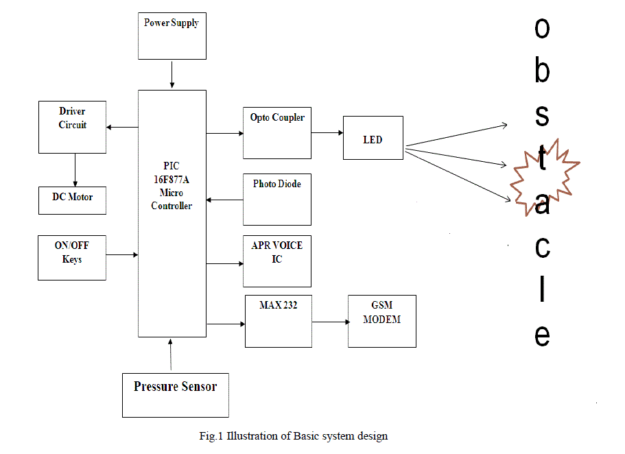
| In the proposed system a device based on optics is designed. The device includes a near-IR LED and a photodiode. The LED emits a train of pulses. These pulses strike the obstacle, and the light is detected by the photodiode. The light detected is processed to determine whether there is a path or not. The LED emits pulses managed by a control unit. The control unit consists of PIC16F877A Microcontroller and Opto coupler Circuit. The control unit increases the amplitude of the pulse step by step. |
| The received amplitude is checked and if it is greater than the threshold, vibration is produced using a DC motor and indicated using voice IC. The absence of vibration indicates that a free path is available. The absence of path is also sent as a message to the care taker using GSM modem. |
SYSTEM DESIGN |
 |
PRINCIPLE OF THE INFRARED DETECTOR |
| The device includes a near-IR LED and a photodiode. The LED emits a train of pulses. These pulses strike the obstacle, and the retro diffused light is detected by the photodiode. The light detected is processed to determine whether there is a path or not. The sensitive surface of the photodiode is placed next to the LED and perpendicularly to the axis of the LED beam. Both components are optically insulated and separated by 15 mm to prevent the emitted light from getting directly into the photodiode. The LED emits pulses managed by a control unit. The control unit increases the amplitude of the pulse step by step. |
| When the signal-to-noise ratio of the photodiode is high enough to detect the presence of the obstacle (detection threshold), the emission is interrupted. The last amplitude of emitted light gives a value. When this value is lower than a constant (arbitrarily fixed, which we will call ―range constant‖), a vibration is sent to the user, which means that there is an obstacle. A lack of vibration means a free path, and the higher the constant, the larger the free path. The choice of the constant determines the range of the device (protection length). The constant and, therefore, the range will be adjustable by the user. In this system, the range depends on the albinos of the obstacles. In practice, this system gives efficient protection to blind people except in the case of specific obstacles. |
| Infrared detection devices are sensors that detect radiation in the infrared portion of the electromagnetic spectrum (>10 12 to 5 × 10 14 Hz). Often, such devices form the information they gather into visible-light images for the benefit of human users; alternatively, they may communicate directly with an automatic system, such as the guidance system of a missile. |
| Because all objects above absolute zero emit radiation in the infrared part of the electromagnetic spectrum, infrared detection provides a means of "seeing in the dark"—that is, forming images when light in the visible portion of the spectrum (>4.3 × 10 14 to 7.5 × 10 14 Hz) is scarce or absent. Because the warmer an object is, the more infrared radiation it emits, infrared imaging is also useful for the detection of outstanding heat sources that may be invisible or hard to detect even when there is ample visible light (e.g., exhaust heat from ships, tanks, jets, or rockets). Many devices used by police, security, and military organizations, including user-wearable, gun mounted, vehicle-mounted, missile-mounted, and orbital systems, exploit some form of infrared detection technology. |
| Infrared—"below-red"—light consists of electromagnetic radiation that is too low in frequency (i.e., too long in wavelength) to be perceived by the human eye, yet is still too high in frequency to be classed as microwave radio. Infrared (IR) light that is just beyond the human visual limit (>1.0 × 10 14 to 4.0 × 10 14 Hz) is termed near IR, while light farther from the visible spectrum is divided into middle IR, far IR, and extreme IR. Military and security systems utilize mostly near IR and a narrow band in the far IR centered on 3.0 × 10 13 Hz, because the Earth's atmosphere happens to be transparent to IR radiation primarily in these two "windows." |
| All objects above absolute zero glow in the far IR, so no source of illumination is needed to image scenes using such radiation; to image scenes in near IR, illumination from a light-emitting diode or filtered light bulb must be supplied. Near- IR imagers, however, are still cheaper than passive, far-IR imagers. |
| There are two basic designs for electronic IR imagers. The first is the scanner. In this design, light from a tiny portion of the scene to be imaged is focused by an optical and mechanical system on a small circuit element that is sensitive to photons in the desired IR frequency range. The intensity of the signal from the IR detector element is recorded, then the mechanic-optical system shifts its focus to a different fragment of the scene. The response of the IR detector element is again recorded; the view shifts again, and so forth, systematically covering the scene. Much scene-covering geometry have been employed by scanning imagers; the scanner may record horizontal or vertical lines (raster’s), spiral outward from a central point, cover a series of radii, and so on. |
| The second basic type of IR imaging system is the "starter." Such a system is said to "stare" because its optics do not move like a scanner's, scanning the scene a little bit at a time; instead, they focus the image onto an extended focal plane. Located in this plane is a flat (planar) array of tiny sensors, each equivalent to the single IR sensor employed in a scanning system. By measuring the IR response of all the elements in the flat array simultaneously (or rapidly), the system can record an entire image at once. Image resolution in a staring scanner is limited by the number of elements in the array, whereas in a scanning system it is limited by the size of the scanning dot. |
| Hybrid designs, in which partial or entire scan-lines are sensed simultaneously by rows of sensors, have also been developed. Chemical films have also proved useful for IR imaging, but these are rarely used today. |
| The earliest IR imagers, built in the 1940s, 1950s, and 1960s, were scanners. Starrers were not technologically feasible until the early 1970s, when large-scale circuit integration made possible the manufacture of focal-plane arrays with good resolution. As integrated-circuit technology has been refined, focal-plane arrays have become cheaper. Starters have many advantages, including greater reliability due to the absence of moving parts, quicker image acquisition, and freedom from internally-produced mechanical vibration. |
ASPECTS OF THE PROJECT |
| Blind people detect obstacles by sweeping their white sticks and by making contact with obstacles. They get hurt, particularly by objects which are located in a high position, such as rears of trucks, branches, advertising boards, etc. These obstacles are a source of stress for blind people when they are walking. The IR device is attached to the white stick with its emission axis placed horizontally. As the user sweeps the white stick to detect obstacles, the system scans in every direction that is taken by the stick; hence, the horizontal protection zone is enlarged . Making a sweep of 10◦ (with the standard length of the cane fitted to the height of the user, 10◦ corresponds to the width of the feet), the tip of the stick protects the user from the hazard of holes. Thus, the user’s body is protected by the IR detector, which anticipates the obstacles. |
| The horizontal detector placed on the cane at about 1 m high does not give a protection area large enough to protect the head. To solve this problem, we have added a second range R3 detector, tilted vertically by 30◦ to protect the head. Using the device requires a training process. The technique to anticipate a side panel, i.e., sweeping the white stick, is quite different from the technique to detect an opening. For a side panel, the device gives off a vibration on one side of the path, and the user must change directions until the vibration remains turned off during the whole sweep of the stick. To find an opening, the user has to perceive a lack of vibration between two side vibrations. When the blind user is walking along a path where there are no vibrations, in ranges R1–R4 (down to 4 m), his/her shoulders are protected even if the perceived path is very narrow. |
| In spite of the simple situations used for the theoretical model, it allows typical real situations to be interpreted. The most important situation when the device is not efficient is sidewalks with thin dark posts. The problem can be solved owing to an additional triangulating laser telemeter, without losing the benefit of the IR sensor, i.e., finding a shoulder width path from a distance exceeding 4 m without perceiving the small details that do not help walking.. |
| The shape of the protection zone is modified by external parameters; the light that strikes the surface can be absorbed, transmitted, and reflected. The surface analyzed is considered as a Lambertian plane in our statements, but in real configurations, some parts of many objects are reflective, and others are diffusive, retro reflective, etc. The light spot on the target has a given width, generally greater than the details of the obstacles. Therefore, it can be represented by an average albedo. |
| The relative ranges used in the current device Tom Pouce II and Minitact are, finally, 6, 4, and 2 m. These ranges are chosen by the user according to his/her speed and the density of obstacles along the path. We have tested two commercially available ultrasonic devices, the Palm sonar and the Miniguide. The test was performed to detect an open door with a width of 0.83 m. The measurement showed us that the Miniguide and the Palmsonar do not detect the difference between an open door and a wall for ranges longer than 0.9 and 1.8 m, respectively. However, the Minitact can detect an opened door with a 6-m range. |
SIMULATION RESULTS |
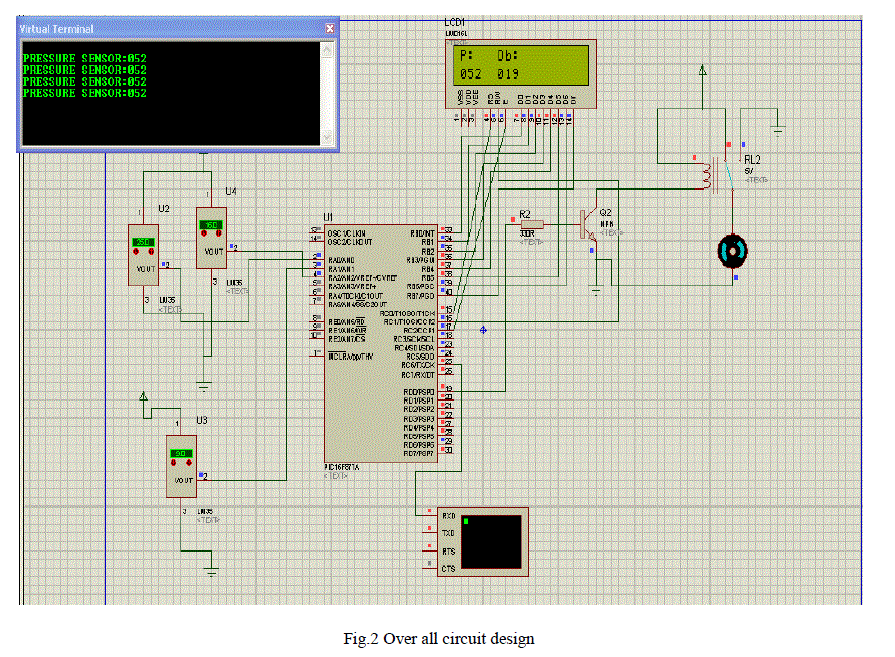
| The automatic energy monitoring, profiling and manage system is simulated using PROTEUS SOFTWARE and their results are presented here. The circuit model of the above system is shown and sensors are connected to measure output result. |
| A. Circuit Design |
 |
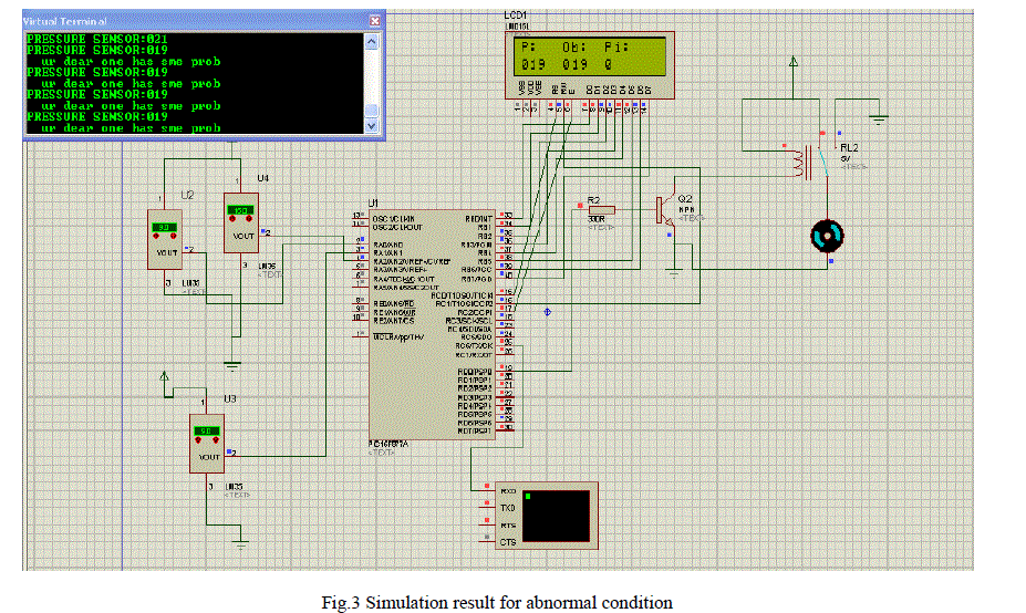
| B. Abnormal condition |
| In normal condition, If the pressure value will be above preset value, the person who has the device is in safe condition. In this condition, if the pressure value is below the set value, it is identified as the person is in abnormal condition. Then the alert message is sent to his/her caregiver through GSM. |
 |
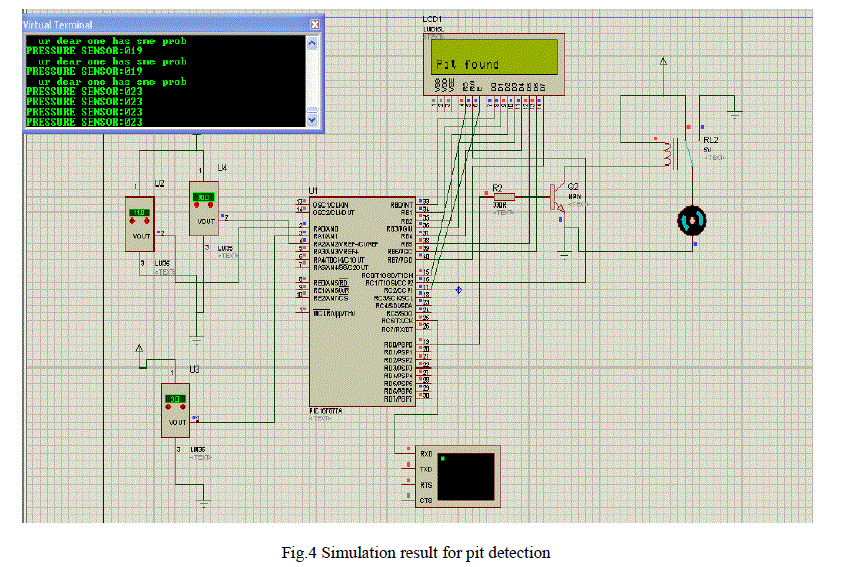
| C. Pit detection |
| Here, the pit is detected by pit sensor. If pit is found, then vibration alert and voice alert will be given to the person by the device itself. |
 |
| D. Object detection |
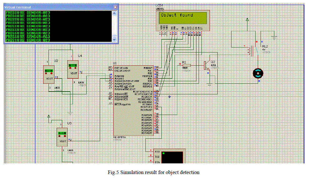
| Here, the object is detected by LED and photo diode. If object is found, then vibration alert and voice alert will be given to the person by the device itself. |
 |
CONCLUSION |
| Typical obstacles (walls, openings, and vertical rods) have been used to draw the protection zone of the IR device. The ability of the IR sensor to find a path wide enough for a person to go through has been demonstrated. Theoretical and radiometric calculations based on optical geometry have been made to improve the design and performance of the system. The importance of intensity distribution to determine the protection zone has been highlighted. The technical compromises used in our new generation of IR devices have been presented. In the near future, we are going to propose a device including the laser telemeter and various IR detectors: The laser detects small parts with low albedos, and the IR detector finds obstacle-free paths that are wide enough for a person to go through. |
ACKNOWLEDGEMENT |
| I articulated my gratitude to Prof.Dr.S.ARUMUGAM, Head of the Department of Electrical and electronics Engineering who had thought as the way to do a successful project and without whose constant encouragement and whole idea, the project would not have been possible. I wish to express my sincere thanks to our project co-coordinator Mr.V.NANDAGOPAL, Assistant Professor who had helped me lot and has given valuable suggestion, which made me to accomplish this project in very successful and next way. |
References |
|