Keywords
|
| Power quality, Dynamic voltage restorer, control methods, compensating techniques. |
INTRODUCTION
|
| Power quality is a very important issue for electricity suppliers, equipment manufactures and customers as sensitive equipment and non-linear loads are becoming common in both the industrial sectors and the domestic environment. So, both, electric utilities and end users of electrical power are becoming concerned about the quality of electric power. Power quality problems are related to voltage as well as current. The major power quality problems in the power system are poor load power factor, DC offset on load voltages, harmonic contents in loads, voltage sag & voltage swell. These power quality problems cause malfunctioning of sensitive equipments; protection and relay system .Faults at either the transmission or distribution level may cause transient voltage sag or swell in the entire system or a large part of it. Also, under heavy load conditions, a significant voltage drop may occur in the system. Voltage sag is one of the most common power quality problems faced nowadays. Voltage sag is a decrease of the normal voltage level between 10 and 90% of the nominal rms voltage at the power frequency, for durations of 0.5 cycle to 1 minute. Voltage swells are momentary increase of the voltage, at the power frequency, outside the normal tolerances, with duration of more than one cycle and typically less than a few seconds. |
| There are various methods to mitigate voltage sags and swells, but the use of a custom Power device is considered to be the most efficient method. There are various custom power devices available each with its own benefits and limitations. Some of these devices include Active Power Filters (APF), Battery Energy Storage Systems (BESS), Distribution STATic synchronous COMpensators (DSTATCOM), Distribution Series Capacitors (DSC), Dynamic Voltage Restorer (DVR), Solid-State Transfer Switches (SSTS), Surge Arresters (SA), Super conducting Magnetic Energy Systems (SMES), Static Electronic Tap Changers (SETC), Solid State Fault Current Limiter (SSFCL), Static Var Compensator (SVC) and Thyristor Switched Capacitors (TSC).The Dynamic Voltage Restorer (DVR) is a device that detects the sag or swells and connects a voltage source in series with the supply voltage in such a way that the load voltage is kept inside the established tolerance limits. It is normally installed in a distribution system between the supply and the critical load feeder at the point of common coupling (PCC). Other than voltage sags and swells compensation, DVR also has added other features like: line voltage harmonics compensation, reduction of transients in voltage and fault current limitations. |
DYNAMIC VOLTAGE RESTORER
|
| Dynamic voltage restorer is a static var device finding application in a variety of transmission and distribution systems. It is a series compensation device, which protects sensitive electric load from power quality problems such as voltage sags, swells, unbalance and distortion through power electronic controllers .Today, the dynamic voltage restorer is one of the most effective PQ devices in solving voltage sag problems. Apart from voltage sag and swell compensation the DVR also helps in line voltage compensation, reduction of transients in voltage and fault current limitations. The basic principle of the dynamic voltage restorer is to inject a voltage of required magnitude and frequency, so that it can restore the load side voltage to the desired amplitude and waveform even when the source voltage is unbalanced or distorted. Generally, it employs a gate turn off thyristor (GTO) solid state power electronic switches in a pulse width modulated (PWM) inverter structure. The DVR can generate or absorb independently controllable real and reactive power at the load side. Thus, the DVR is made of a solid state DC to AC switching power converter that injects a set of three phase AC output voltages in series and synchronism with the distribution line voltages. |
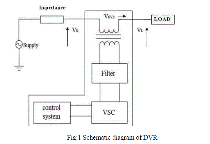
| Dynamic voltage restorer is a series connected device designed to maintain a constant RMS voltage across a sensitive load. The structure of DVR is shown in Fig.1. |
 |
| The DVR consists of: |
| i) Voltage Source Converter (VSC) |
| ii) Injection Transformer |
| iii) Passive Filters |
| iv)Energy storage device |
| i. Voltage Source Converter (VSC): |
| A Voltage Source Converter is a power electronic system consisting of a storage device and switching devices, which can generate a sinusoidal voltage at any required frequency, magnitude, and phase angle. In the DVR application, the VSC is used to temporarily replace the supply voltage or to generate the part of the supply voltage which is missing. The missing voltage is the difference between the nominal voltage and the actual. The converter is normally based on some kind of energy storage, which will supply the converter with a DC voltage. The solid-state electronics in the converter is then switched to get the desired output voltage. Normally the VSC is not only used for voltage dip mitigation, but also for other power quality issues, e.g. flicker and harmonics. |
| ii. Injection Transformer: |
| Injection transformers plays a vital role in ensuring the maximum reliability and effectiveness of the restoration scheme. It is connected in series with the distribution feeder.]. Its main task is to connect the DVR to the distribution network via the HV-windings and transform and couple the injected compensating voltages generated by the voltage source converters to the incoming supply voltage. It also isolates the load from the system. |
| iii. Passive Filters: |
| Passive Filters are placed at the high voltage side of the DVR in order to filter the harmonics. These filters are placed at the high voltage side as placing the filters at the inverter side introduces phase angle shift which can disrupt the control algorithm. |
| iv. Energy storage device: |
| The DVR requires real power for compensation during voltage disturbances in the distribution system. In this case the energy storage supplies the real power to the DVR when the voltage disturbances exit. The energy storage such as a battery is responsible to supply an energy source in DC form. Other examples of energy storage devices are dc capacitors, super-capacitors, superconducting magnetic energy Storage and flywheels. The capacity of energy storage device has a big impact on the compensation capability of the system. Compensation of real power is essential when large voltage sag occurs. |
VOLTAGE INJECTION METHODS
|
| Voltage injection or compensation methods by means of a DVR depend upon DVR power ratings, various conditions of load, and different types of voltage sags. Some loads are sensitive towards phase angle jump while some are sensitive towards change in magnitude. Therefore the control strategies depend upon the type of load characteristics. There are four different methods of DVR voltage injection which are |
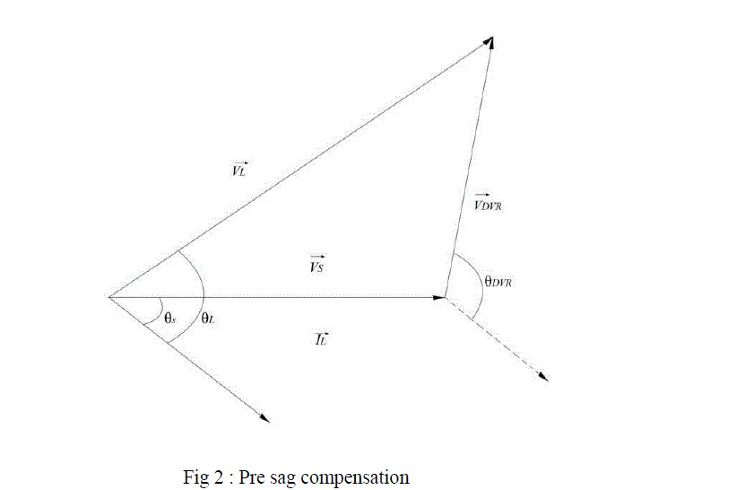
| 1. Pre-sag compensation method |
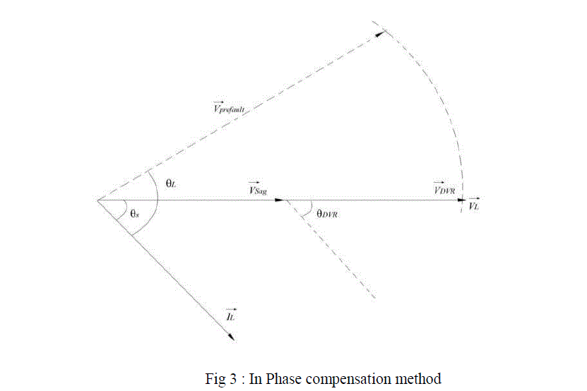
| 2. In-phase compensation method |
| 3. In-phase advanced compensation method |
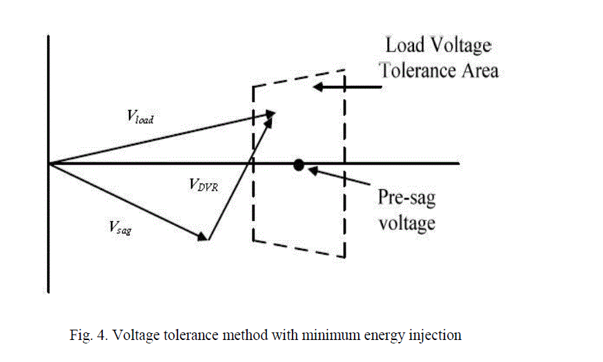
| 4. Voltage tolerance method with minimum energy injection |
| 1. Pre-Sag Compensation : |
| The pre-sag method tracks the supply voltage continuously and compensates load voltage during fault to pre-fault condition When it detects any disturbances in supply voltage it injects the difference voltage between the sag or voltage at PCC and pre-fault condition, so that the load voltage can be restored back to the pre-fault condition. Compensation of voltage sags in the both phase angle and amplitude sensitive loads would be achieved by pre-sag compensation method. In this method the injected active power cannot be controlled and it is determined by external conditions such as the type of faults and load conditions This method is achieved by using a fault detector to freeze the output from the Phase Locked Loop (PLL) circuit, when the fault occurs. |
| The voltage of DVR is given as: |
| VDVR = Vprefault – Vsag |
 |
| B. In phase Compensation method: |
| It is the most straight forward method in which the injected voltage is in phase with the supply side voltage irrespective of the load current and pre-fault voltage. The phase angles of the pre-sag and load voltage are different but the most important criteria for power quality is that the constant magnitude of load voltage are satisfied. One of the advantages of this method is that the amplitude of DVR injection voltage is minimum for certain voltage sag in comparison with other strategies. |
 |
| C. In Phase advanced compensation: |
| In this method the real power spent by the DVR is decreased by minimizing the power angle between the sag voltage and load current. In case of pre-sag and in-phase compensation method the active power is injected into the system during disturbances. The active power supply is limited stored energy in the DC links and this part is one of the most expensive parts of DVR. The minimization of injected energy is achieved by making the active power component zero by having the injection voltage phasor perpendicular to the load current phasor. In this method the values of load current and voltage are fixed in the system so we can change only the phase of the sag voltage. IPAC method uses only reactive power and unfortunately, not al1 the sags can be mitigated without real power, as a consequence, this method is only suitable for a limited range of sags. |
| D. Voltage tolerance method with minimum energy injection: |
| A small drop in voltage and small jump in phase angle can be tolerated by the load itself. If the voltage magnitude lies between 90%-110% of nominal voltage and 5%-10% of nominal state that will not disturb the operation characteristics of loads. Both magnitude and phase are the control parameter for this method which can be achieved by small energy injection. |
 |
CONTROL TECHNIQUES
|
| A. Linear controllers : |
| The three main voltage controllers, which have been proposed in literature, are Feed forward (open loop), Feedback (closed loop) and Multi-loop controller . The feed-forward voltage controller is the primary choice for the DVR, because of its simplicity and fastness. The supply voltage is continuously monitored and compared with a reference voltage; if the difference exceeds a certain tolerance, the DVR injects the required voltage. The drawback of the open loop controller is the high steady state error. In the feedback control, the load voltage is measured and compared with the reference voltage, the missing voltage is supplied by the DVR at the supply bus in a feedback loop. This controller has the advantage of accurate response, but it is complex and time-delayed. Multi-loop control is used with an outer voltage loop to control the DVR voltage and an inner loop to control the load current. This method has the strengths of feed-forward and feedback control strategies, on the expense of complexity and time delay. |
| B. Non-linear Controllers: |
| It appears that the nonlinear controller is more suitable than the linear type since the DVR is truly a non-linear system due to the presence of power semiconductor switches in the inverter bridge. The most non-linear controllers are the Artificial Neural Networks (ANN), Fuzzy Logic (FL) and Space Vector Pulse Width Modulation (SVPWM) . ANN control method has adaptive and self-organization capacity. The ANN has inherent learning capability that can give improved precision by interpolation. FL controllers are an attractive choice when precise mathematical formulations are not possible. When a FL controller is used, the tracking error and transient overshoots of PWM can be considerably reduced. SVPWM control strategy is to adopt a space vector of the inverter voltage to get better performance of the exchange is gained in low switching frequency conditions. |
CONCLUSION
|
| A review of voltage profile enhancement with the help of DVR is presented in this paper. Using different control techniques it is found that DVR is suitable for voltage sag and swell mitigation. The basic structure of DVR, its operation, compensation methods and control techniques are discussed in detail. DVR is considered to be an efficient solution due to its low cost, small size, and fast dynamic response. DVR provides simpler implementation for voltage profile improvement. Linear controllers provide simpler operation and less computational efforts as compared to other methods. |
References
|
- Chellali BENACHAIBA, Brahim FERDI “Voltage Quality Improvement Using DVR” Electrical Power Quality and Utilisation, Journal Vol. XIV, No. 1, 2008
- M.Sharanya, B.Basavaraja , M.Sasikala “ An Overview of Dynamic Voltage Restorer for Voltage Profile Improvement” International Journal of Engineering and Advanced Technology (IJEAT) ISSN: 2249 – 8958, Volume-2, Issue-2, December 2012
- Yusuf I. Nakhoda, Abraham Lomi, Member, IEEE “Implementation of Dynamic Voltage Restorer (DVR) and Distribution Static Compensator(D-STATCOM) for Power Quality Improvement.”
- H.P. Tiwari and Sunil Kumar Gupta ” Dynamic Voltage Restorer against Voltage Sag” International Journal of Innovation, Management and Technology, Vol. 1, No. 3, August 2010 ISSN: 2010-0248
- Shairul Wizmar Wahab and Alias Mohd Yusof, “ Voltage Sag and Mitigation Using Dynamic Voltage Restorer (DVR) System” ELEKTRIKA, VOL. 8, NO. 2, 2006, 32-37.
- T.Devaraju, Dr V.C.Veera Reddy, Dr M.Vijay kumar “ Modelling and simulation of custom power devices to mitigate power quality problems” International Journal of Engineering Science and Technology Vol. 2(6), 2010, 1880-1885
|