Keywords
|
| Dynamic Voltage Restorer, Voltage Sags, Voltage Swells, Power quality. |
INTRODUCTION
|
| As well known, quality of the power is facing a various problems such as voltage sags/swells, surge, flicker, voltage imbalance, interruptions and harmonic distortion, Voltage sags/swells can occur more frequently than other Power quality problems, also these sags/swells are the most severe power quality disturbances in the power distribution system. One of the most important custom power devices that have been created to improve the performance of power quality is Dynamic Voltage Restorer (DVR). The DVR maintains the load voltage at a nominal magnitude and phase by compensating the voltage sag/swell and voltage unbalance at the point of common coupling (PCC). These systems are able to compensate voltage sags by increasing the appropriate voltages in series with the supply voltage, and therefore prevent loss of power [1]. |
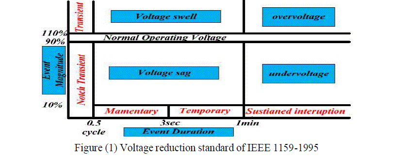
| Voltage sags/swells caused by unsymmetrical line-to-line, single line-to-ground (SLG), double line-toground and symmetrical three phase faults. the DVR injects the independent voltages to restore and maintained sensitive to its nominal value The injection power of the DVR with zero or minimum power for compensation purposes can be achieved by choosing an appropriate amplitude and phase angle [10].Voltage sags can occur at any instant of time, with amplitudes ranging from 10-90% and a duration lasting for half a cycle to one minute. Voltage swell, on the other hand, is defined as an increase in rms voltage for durations from 0.5 cycles to 1 minute. Typical magnitudes are between 1.1 and 1.8 up. IEEE 519 1992 and IEEE 1159-1995 describe the voltage sags/swells as shown in Figure 1. |
 |
| Due to the fact that voltage swells are less common in distribution systems, they are not as important as voltage sags. Voltage sag and swell can cause sensitive equipment (such as found in semiconductor or chemical plants) to fail, or shutdown, as well as create a large current unbalance that could blow fuses or trip breakers. These effects can be very expensive for customers, ranging from minor quality variations to produce downtime and equipment damage [2]. Nielsen et al, proposed various system topologies and are verified and compared for checking the DVR performance [3]. The post fault method control strategy for DVR has been presented by Vilathgamuwa and Parera[4]. In this either minimum voltage or minimum energy DVR operation has been achieved based on phase-locked loop (PLL). Marie et. al, presented minimum voltage control strategy for DVR based on the symmetrical components[5]. A simple DVR was proposed, in which the Fourier Transform (FT) has been applied for the sag detection [6]. The Hbridge multilevel IGBT VSC with closed loop control scheme is used for mitigation of balanced/unbalanced voltage sag only. In this, DVR structure based on a cascaded H-bridge multilevel inverter topology to eliminate the need of insertion transformer has been used [7]. In the work of M. I. Marei et.al, an energy optimized control scheme for a transformer less DVR has been presented [8]. The D.C. link minimum energy injection control method is presented the work of Il-Yop Chung et.al. The DVR is connected in series with the load and it is a direct voltage control method. The shunt connected compensators are indirect controller in which line current is controlled. Hence DVR is an effective compensator for dynamic PQ disturbances [9]. The design and analysis of the inverter- side filter used for DVR has been presented in the work of S. S. Choi et.al [10]. C. Zang et. al work presents a three dimensional voltage space vector PWM algorithm to analyze the four-wire DVR[11]. The techniques of the supply voltage compensation with minimum energy are presented in the work of M.R. Banaei et.al [12]. |
| This paper presents a result of proposed controller which is designed for compensating multiple voltage sag/swell. The proposed controller causes DVR to reacts quickly to maintain constant load voltage both for a balanced and unbalanced multiple sag/swell conditions in the distribution systems. One of the main advantages of DVR is that it inject (absorb) energy during sag (swell) to maintain load voltage constant. The DVR, which is a series compensator, protects a sensitive load from the distortion and unbalance in the supply side voltage. |
SYSTEM MODEL AND ASSUMPTIONS
|
| In 1994, L. Gyugyi proposed a device and a method for dynamic voltage restoration of utility distribution network. This method uses real power in order to inject the faulted supply voltages and is commonly known as the Dynamic Voltage Restorer [14]. In this paper, a DVR design essentially contains a voltage source inverter (VSI), an injection transformer connected between the AC voltage supply and the sensitive load, a DC energy storage device, and a control system as shown in Figure 2. |
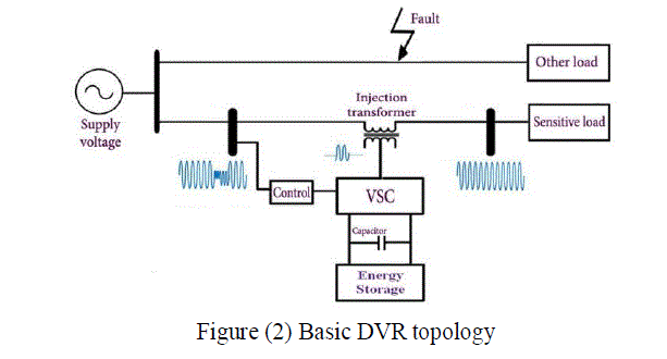 |
| The main function of the DVR is the protection of sensitive loads from voltage sags/swells coming from the network. The DVR is connected in series between the source voltage or grid and sensitive loads through injection transformer. There are several types of energy storage that has been used in the DVR such as battery, capacitance and superconducting coil. These types of energy storages are very important in order to supply active and reactive power to the DVR. The controller is an important part of the DVR for switching purposes. The switching converter is responsible to do conversion process from DC to AC and to make sure that’s only the swell or sag voltage is injected to the injection transformer. |
| The three-phase transformers connection used in the three-phase DVR can be configured either in delta/open or star/open connection. In case of asymmetrical fault in the high voltage side, the zero sequence current flowing almost zero, if the distribution transformer connection in Ä-Y with the grounded neutral. As such connection, the DVR only mitigates the positive and negative sequence components [15]. |
COMPENSATION METHODS IN DVR
|
| The type of the compensation strategy mainly depends upon the limiting factors such as DVR power ratings, various conditions of load, voltage sag type. Some loads are sensitive towards phase angel jump and some are sensitive towards change in magnitude and others are tolerant to these [16]. Therefore, the control strategies depend upon the type of load characteristics; there are three different methods of DVR voltage injection which are: |
| (A) Pre-sag compensation method |
| (B) In-phase compensation method |
| (C) Voltage tolerance method with minimum energy injection |
| (A) Pre-Sag/Dip Compensation Method |
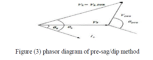
| The pre-sag method tracks the supply voltage continuously and if it detects any disturbances in supply voltage it will inject the difference voltage between the sag or voltage at PCC and pre-fault condition, so that the load voltage can be restored back to the pre-fault condition. Compensation of voltage sags in the both phase angle and amplitude. Sensitive loads would be achieved by pre-sag compensation method as shown in Figure 3. In this method the injected active power cannot be controlled and it is determined by external conditions such as the type of faults and load conditions. The voltage of DVR is given below: |
| VDVR = V pre fault –Vsag |
 |
| (B) In-Phase Compensation Method |
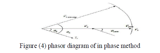
| In this method the injected voltage is in phase with the supply side voltage irrespective of the load current and prefault voltage as shown in Figure 4. The phase angles of the pre-sag and load voltage are different but the most important criteria for power quality that is the constant magnitude of load voltage are satisfied. The load voltage is given below: |
| |VL| = |Vpre-fault| |
| One of the advantages of this method is that the amplitude of DVR injection voltage is minimum for certain voltage sag in comparison with other strategies. Practical application of this method is in non-sensitive loads to phase angle jump. |
 |
| (C) Voltage Tolerance Method with Minimum Energy Injection |
| A small drop in voltage and small jump in phase angle can be tolerated by the load itself. If the voltage magnitude lies between 90%-110% of nominal voltage and phase angle variations between 5% -10% of nominal state that will not disturb the operation characteristics of loads. Both magnitude and phase are the control parameter for this method which can be achieved by small energy injection. In this method, the phase angle and magnitude of corrected load voltage within the area of load voltage tolerance are changed. The small voltage drop and phase angle jump on load can be tolerated by load itself. The sensitivity of loads to phase angle jump and voltage magnitude is different. |
 |
PROPOSE CONTROL TECHNIQUE
|
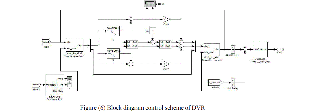
| The control system of a DVR plays an important role, with the requirements of fast response when voltage sag/swells are occur. When voltage sag/swells are detected, the DVR should react as fast as possible and injects AC voltage to the grid. It can be implemented using a Space Vector PWM control technique based on the voltage reference and instantaneous values of supply and load voltage. There are various basic rules of a controller in a DVR: detection of the voltage sag/swell occurrences in the system; calculation of the compensating voltage, generation of the trigger pulses of PWM inverter and stop triggering pulses when the occurrence has passed. The dq0 method gives the information of the depth (d) and phase shift (q) of voltage sag with start and end time. The load voltage is transformed to VD, VQ and V0 based on park transformation according equations (1), (2) & (3). |
 |
 |
 |
| Phase locked loop (PLL) is used to generate unit sinusoidal wave in phase with main voltage. The abc components are given to generate three phase pulses using PWM technique. Proposed control technique block is shown in Figure 6. |
 |
SIMULATIONS AND RESULTS
|
| Investigation on the DVR performance can be observed through testing under various disturbances condition on the source voltage. The proposed control algorithm was tested for balanced and unbalanced voltages sags/swells in low voltage distribution system. |
 |
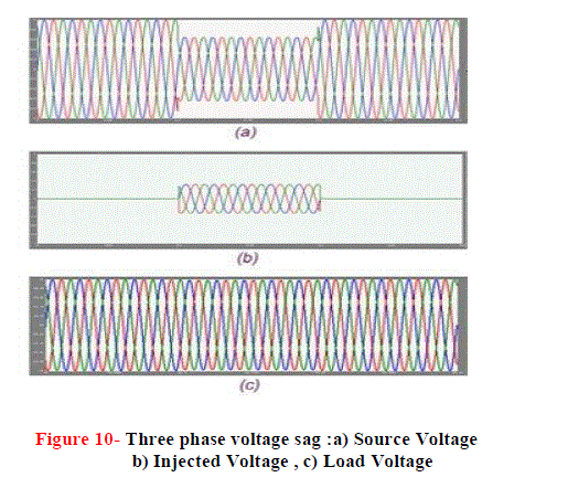 |
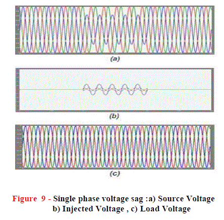
| The first simulation shows the single phase voltage sag. The simulation started with the supply voltage 50% sagging as shown in Figure 9 (a) also shows a 50% voltage sag initiated at 0.1 sec and it is kept until 0.2 sec, with total voltage sag duration of 0.1 sec. Figure 9 (b) illustrates the voltage injected by the aid of DVR and (c) shows the corresponding load voltage with compensation. As a result of the DVR, the load voltage is kept at 1 PU. The Figure 10 shows the occurrence of 50% three phase voltage sag on utility grid, also the injected voltage and load voltage are shown as above. |
 |
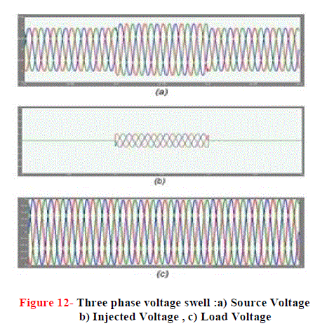 |
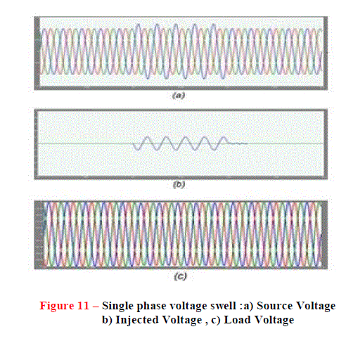
| The second simulation shows the DVR performance during a voltage swell condition. In case of balance voltage swell, the source voltage has increased about 20- 25% of its nominal value. The simulation results of the balance three phase voltage swell as shown in Figure 12(a). Figures 12(b) and (c) show the injected and the load voltage respectively. The swells voltages occur at the time duration of 0.1 sec and after 0.2 sec the voltage will restore back to its normal value. As can be seen from the results, the load voltage is kept at the nominal value with help of the DVR. Figures 11 (a), (b), and (c) show the single phase voltage swell, injected voltage by the DVR and the load voltage respectively. In addition, as a result of SLG fault. An unbalanced voltage sag is created immediately after the fault as shown in Figure 13(a), the supply voltage with two of the phase voltages dropped down to 60-80%. |
CONCLUSION
|
| A comprehensive study of a DVR as a powerful custom power device has been shown with aid of matlab/Simulink. The main advantages of DVR are low cost, simpler implementation, require less computational efforts and its control is simple as compared to other methods. The simulation shows that the DVR performance is efficient in mitigation of voltage sags and swells. The DVR handles both balanced and unbalanced situations without any difficulties. It injects an appropriate voltage component to correct any anomaly rapidly in the supply voltage; in addition, it keeps the load voltage balanced and constant at the nominal value, such PQ disturbances in the distribution system is also compensated effectively by the proposed control strategy . |
References
|
- A.A.D.R. Perera, D.M. Vilathgamuwa, S.S. Choi, “Voltage Sag Compensation with Energy Optimized Dynamic Voltage Restorer”, IEEE Trans. on Power Del., Vol. 11, No. 3, pp. 928-936, July 2003.
- B.H. Li, S.S. Choi, D.M. Vilathgamuwa, “Design Considerations on the Line-Side Filter Used in the Dynamic Voltage Restorer”, IEE Proc. Gener. Transmission Distrib., Issue 1, Vol. 148, pp. 1-7, Jan. 2001.
- H.P. Tiwari, Sunil Kumar Gupta, “DC Energy Storage Schemes for DVR Voltage Sag Mitigation System” International Journal of Computer Theory and Engineering, Vol. 2, No. 3, June, 2010.
- P. Boonchiam , N. Mithulananthan, “Understanding of Dynamic Voltage Restorers through Matlab Simulation” Thammasat Int. J. Sc. Tech., Vol. 11, No. 3, July-Sept. 2006.
- M.R. Banaei, S.H. Hosseini, S. Khanmohamadi, G.B. Gharehpetian, “Verification of a New Control Strategy for a Dynamic Voltage Restorer by Simulation”, Elsevier Simulation Modeling Practice and Theory, Vol. 14, pp. 112-125, March 2006.
- B.J. Quirl, B.K. Jhonson, H.L. Hess, “Mitigation of Voltage Sags with Phase Jamp Using a Dynamic Voltage Restorer”, 38th Power Symposium, Carbondal, IL , North American, pp. 647-654, Sept. 2006.
- Yash Pal, A. Swarup, Senior Member, IEEE, and Bhim Singh, Senior Member, IEEE “A Review of Compensating Type Custom Power Devices for Power Quality Improvement” IEEE Power India Conference, pp. 1-8, 2008.
- S.S. Mahesh, M.K. Mishra, B.K. Kumar, V. Jayashankar, “Rating and Design Issues of DVR Injection Transformer”, Power Electronics Conference and Exposition, pp. 449-455, Feb. 2008.
- A. Ramasamy, V.K. Ramachandaramurthy, R.K. Iyer, Z.L. Liu, “Control of Dynamic Voltage Restorer Using TMS320F2812”, Electrical Power Quality and Utilisation Conference, pp. 1-6, Oct. 2007.
- H. Toodeji, S.H. Fathi. “Cost Reduction and Control System Improvement in Electrical Arc Furnace Using DVR”, IEEE Conference on Industrial Electronics and Applications, pp. 211-215, Tehran, Iran, May 2009.
- L. Gyugyi, C.D. Schauder, C.W. Edwards, M.Sarkozi, “Apparatus and Method for Dynamic Voltage Restoration of Utility Distribution Networks”, U.S. Patent, Issue 1, Vol. 5, pp. 329-222, 1994.
- A.O. Ibrahim, T.H. Nguyen, D.C. Lee, “A Fault Ride-Through Technique of DFIG Wind Turbine Systems Using Dynamic Voltage Restorers”, IEEE Transaction Energy Conversion, Vol. 26, No. 3, pp. 871- 882, Sept. 2011.
- C. Fitzer, M. Barnes, P. Green, “425Voltage Sag Detection Technique for a Dynamic Voltage Restorer”, IEEE Transactions on Industry application, Issue 1, Vol. 40, pp. 203-212, Feb. 2004.
- John Godsk Nielsen, FredeBlaabjerg, “Control Strategies for Dynamic Voltage Restorer Compensating Voltage Sags
- S. Deepa, S. Rajapandian, “Voltage Sag Mitigation Using Dynamic Voltage Restorer System by Modified Z-Source Inverter”, 2nd International Conference on Electrical, Electronics and Civil Engineering (ICEECE’2012), pp. 1-4, April 2012
- M. Karimian, A. Jalilian, “Proportional Repetitive Control of a Dynamic Voltage Restorer (DVR) for Power Quality Improvement”, International Journal on Technical and Physical Problems of Engineering (IJTPE), Issue 11, Vol. 4, No. 2, pp. 18-23, June 2012.
- Mokhtarpour, H.A. Shayanfar, S.M.T. Bathaee, “Extention of Fourier Transform for Very Fast Reference Generation of UPQC”, International Journal on Technical and Physical Problems of Engineering (IJTPE), Issue 9, Vol. 3, No. 4, pp. 120-126, Dec. 2011.
- A.Teke, K.Bayindir, M.Tumay, Department of Electrical and Electronics Engineering, Cukurova University, Adana, Turkey “Fast sag/swell detection method for fuzzy logic controlled dynamic voltage restorer” generation transmission and distribution IET, vol. 4, pp. 1- 12, 2010.
|