ISSN ONLINE(2278-8875) PRINT (2320-3765)
ISSN ONLINE(2278-8875) PRINT (2320-3765)
Charanjeet Madan1, Puneet Pahuja1 and Charu Jain2
|
| Related article at Pubmed, Scholar Google |
Visit for more related articles at International Journal of Advanced Research in Electrical, Electronics and Instrumentation Engineering
In this paper, the process of designing of Unified Power Quality Conditioner (UPQC) including series active power filter, shunt active power filter, a dc link is shown for the reduction in harmonics. In this main focus is on the control system of UPQC that reduces the problem of voltage and current simultaneously. Industrial and sensitive loads can cause various types of power quality problems. Unified Power Quality Conditioner enhances electric power quality mainly at distribution level. By using UPQC problem of voltage sag, voltage swell and current distortion in distribution system can be easily reduced. Moreover, a comprehensive control strategy is also introduced to extract the compensating signals for the control of series and shunt active filters. The proposed control scheme to mitigate the power quality issues is simulated using MATLAB/ SIMULINK in power system block set.
Keywords |
| Active Power Filter (APF), harmonic compensation, power quality, Unified Power Quality Conditioner (UPQC), custom power devices. |
INTRODUCTION |
| The important factors to be considered in power quality measurement are the active power, reactive power, variation of voltage and current, flicker, harmonics, and electrical behaviour of switching operation [1]. According to definition of power quality given in IEEE standard, “Power quality is the concept of powering and grounding sensitive equipment in a matter that is suitable to the operation of that equipment.” Serious problems in electrical systems is the increasing number of electronic components of devices that are used by industry as well as residences and increasing use of nonlinear loads is the main cause for increased voltage, current and harmonics issues[6][9]. |
| In recent years, the development of power electronics devices has been led for the implementation of electronic equipment which is suitable for electrical power systems [8]. These types of devices allow great flexibility in: a) controlling the power flow in transmission systems using Flexible AC Transmission System (FACTS) devices, b) enhancing the power quality in distribution systems employing Custom Power devices [10][11]. Harmonic current components create several problems like |
| 1. Increase in power system losses, |
| 2. Overheating and insulator failures in transformers, rotating machinery, conductor, and cables, |
| 3. Reactive power burden, |
| 4. Low system efficiency, |
| 5. Poor power factor, |
| 6. System unbalances and causes excessive neutral currents, |
| 7. Malfunctioning of the protective relays and untimely tripping. |
| One of the effective approaches is to use a UPQC at point of common coupling (PCC) for the protection of sensitive loads. It is a combination of shunt and series active power filters, sharing a common dc link as shown in Fig.1 [2]. It is the only versatile device which can easily mitigate many power quality problems related with voltage and current simultaneously. It also compensates almost all power quality problems like voltage harmonics, voltage unbalance, voltage flickers, voltage sags & swells, current harmonics, reactive current, current unbalance, and can also be used to prevent harmonic load current from entering into the power system [3]. |
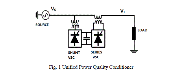 |
| UPQC consists of two IGBT based Voltage source converters (VSC), one shunt connected active filter and one series connected active filter cascaded by a common DC link. The shunt APF provides VAR support to the load and supply harmonic currents to prevent it from entering into the power system. Whenever the supply voltage undergoes sag then series APF injects suitable voltage with supply and can compensates all voltage related problems such as voltage harmonics, voltage swell, flicker etc.[2][7]. Thus UPQC improves the power quality by preventing load current harmonics and by correcting the input power factor. |
CONTROL STRATEGIES OF UPQC |
| The control systems of UPQC consist of shunt APF and series APF controllers. Shunt APF controller measures the load voltages, capacitor voltage, load currents and injected currents. The controller algorithm of shunt APF processes the measured values and generates the required compensation signals [8]. These signals are then compared in hysteresis controller and the required gate signals are generated. Series APF controller measures the supply voltages to generate the required compensation and sag/swell detection signals. These signals are then compared in PWM controller and the required gate signals are generated. |
| A. Control Algorithms for shunt APF |
| In this thesis, a simple and effective control algorithm is proposed for reference current generation. It presents some interesting features [9], namely: |
| 1. It is a three phase system theory. |
| 2. It is based on instantaneous values, allowing excellent dynamic response. |
| 3. Its calculations are relatively simple (it only includes algebraic expressions that can be implemented using standard processors). |
| 4. It allows two control strategies: constant instantaneous supply power and sinusoidal supply current. |
| The control system of the shunt APF is shown in Fig. 2. Inputs given to the control system are three-phase load voltages, load currents, DC capacitor voltage, and injected currents. The capacitor voltage is controlled by using discrete PI controller. The outputs of the control system are the reference currents (Ia, Ib and Ic). This obtained error signals are compared with hysteresis controller and required gate signals are generated for IGBT switches. |
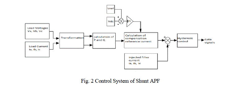 |
| 1) Reference Current Generation: The feedback method is used to control self-supporting DC bus which is very important. This method consists of controlling the capacitor voltage to a reference value [4]. To achieve this, a PI controller is chosen for the error between the reference value and the capacitor voltage value. The result comes out compensates the power lost. This value modifies the reactive power, which appears in the current compensation [12]. |
| 2) Hysteresis Current Controller: The basic of the hysteresis current control is based on an error signal between injections current (I inj.) and a reference current of APF (I ref.) which produces proper control signals. The hysteresis band current controller decides the switching pattern of APF [3]. There are bands above and under the reference current. When the error reaches to the upper limit, the current is forced to decrease. When the error reaches to the lower limit, the current is forced to increase. |
| Some significant advantages of hysteresis controllers over other types of controllers designed nonlinear control techniques for APF applications are as follows: |
| 1. Switching behaviour of the power inverter can be directly taken into account at the design level. |
| 2. Robustness to load parameters variation can be proved. |
| 3. Almost static response is achieved (the dynamics are obviously bounded by the DC-link voltage and by the actual switching frequency). |
| 4. Simple hardware implementations based on logical devices are possible according to Boolean nature of controller input/output variables. |
| B. Control Algorithms for Series APF |
| The control system of series APF performs voltage measurements, sag/swell detection, reference voltage extraction and gate signal generation. Simple and effective control algorithms are proposed for both sag detection and reference voltage generation in this thesis. The algorithms are based on the nonlinear adaptive filter is presented [5]. The filter has also the abilities of peak detection and signal decomposition. This filter can be used as a PLL. Its performance is immune to noise and external distortions, accuracy and speed of its response are controllable and its structural simplicity provides major advantage series APF control includes the reference voltage generation and sag/swell detection computations [13]. |
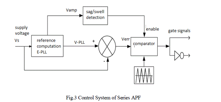 |
| The required compensation signal Verr is obtained from V-PLL and this signal are used to detect voltage sags/swells. The measurements of supply voltages are required for control strategy of series APF. |
| E-PLL extracts and directly provides the following pieces of information from the input [5-6]. |
| 1. Fundamental sinusoidal component of this signal is synchronous with the input and is smooth and noise-free. |
| 2. Amplitude of the fundamental component of the input varies according to the load. |
| 3. Phase angle of the fundamental component of the input phase can be adjusted to be its constant. |
| When the supply voltage is within the nominal operation values, series APF is in OFF-mode (standby). When the supply voltage deviates from its nominal operation value, series APF comes into ON-mode. In this method, minimum energy is injected and switching losses are reduced. |
SIMULATION STUDY OF UPQC |
| The role of unified power quality conditioner for power quality improvement is carried out for distribution network having nonlinear load. |
| A. Non Linear Load |
| A load is considered to be non-linear if its impedance changes with the applied voltage. The changing impedance means that the current drawn by the non-linear load will not be necessarily sinusoidal even when supply given to load is sinusoidal voltage supply. Non-sinusoidal currents contain harmonic currents that can interact with the impedance of the distribution system to create voltage distortion. Distortion can affect both the distribution system equipment and the loads connected to it. Harmonic problems are now common in not only industrial area but in commercial buildings as well. |
| B. Parameters of Test System |
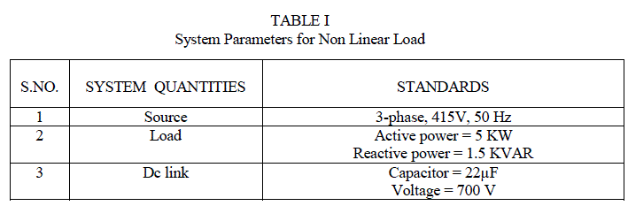
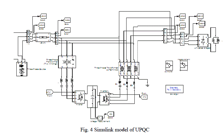
| Simulation model of UPQC using discrete PI controller and non linear load is shown in Fig.4. System parameters of test system are listed in Table 1. |
 |
| C. Proposed UPQC Model |
| An ideal three-phase sinusoidal supply voltage is applied to the non-linear load injecting current and voltage harmonics into the system. For the best performance, UPQC is placed between two sections source and nonlinear load of the transmission line. UPQC consists of a series active filter and a shunt active filter. Figure 4 shows basic system configurations of a general unified power quality conditioner consisting of the combination of a series active filter and a shunt active filter. Matlab/Simulink model of the proposed UPQC is shown in Figure 4. The model can be divided into three main parts: |
| 1. DC link regulator |
| 2. Series connected active power filter |
| 3. Shunt connected active power filter |
 |
RESULTS AND DISCUSSIONS |
| The performance of the proposed UPQC is evaluated under Matlab / Simulink. Under normal conditions, three-phase voltages and currents are sinusoidal but when we are using non linear load then it generates harmonics at a high distortion level. UPQC is expected to compensate the harmonics produced by nonlinear load (diode rectifier feeding an RL load), eliminate voltage sags and provide reactive power compensation at PCC. The results demonstrate the effectiveness of the proposed UPQC. Shunt APF generates harmonic content of the load current but with opposite polarity such that when they are injected at the point of common coupling the harmonic content of supply current is effectively reduced and this reduced value remains constant by using discrete PI controller. |
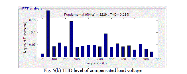
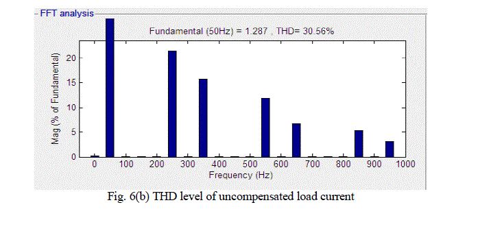
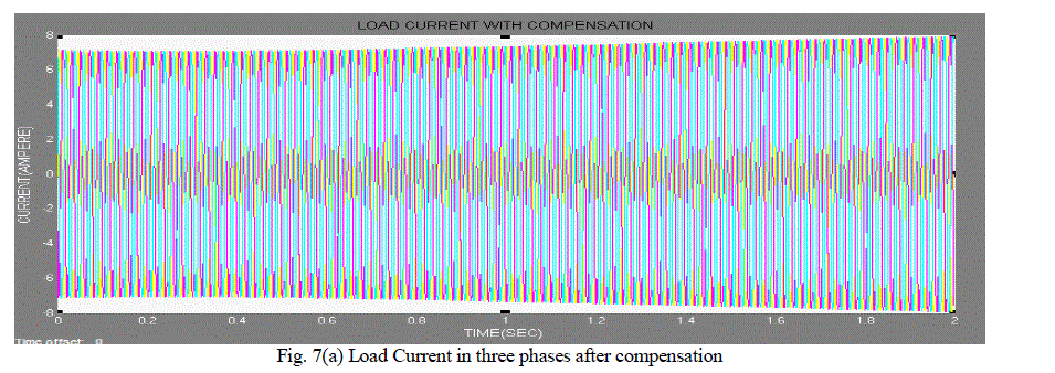
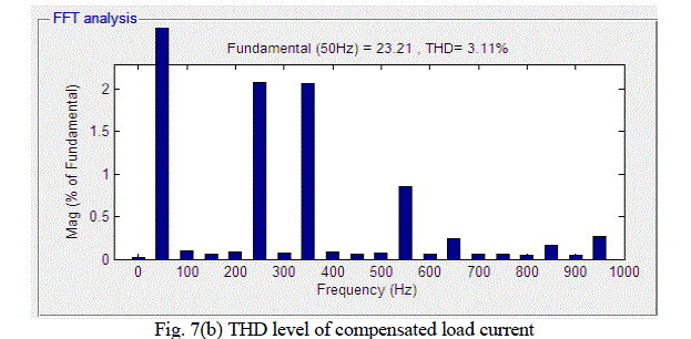
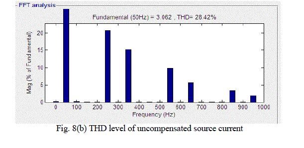
| Fig. 5(a) shows load voltage in three phases after compensation. Fig. 5(b) shows Total Harmonic Distortion (THD) level for compensated load voltage. This shows that after using UPQC distortion in load voltage reduces from 8.78% to 0.29% by using discrete PI controller. Fig. 6(a) shows load current in three-phase before compensation and Fig. 6(b) shows THD level for uncompensated load current. Figure 9(a) shows source current in three-phase after compensation. Fig. 9(b) shows THD level for compensated source current. After compensation, source current becomes sinusoidal and in phase with the source voltage; hence reactive power and harmonics both are compensated simultaneously. After placing UPQC in distribution network it prevents other linear load from distortion. The THD for load current which was 30.56% in Fig 6(b) after compensation it reduces to 3.11 % in fig 7(b) using discrete PI controller. UPQC also prevents the harmonic currents from entering into the power system as well as their distortion level as shown in simulated results of load current and source current after compensation. Before harmonic compensation, the THD of the supply current is 28.42% and after the harmonic compensation, it is reduced to .01% which complies with the IEEE 519 harmonic standards. |
 |
 |
 |
 |
 |
 |
 |
 |
 |
 |
| Three phase diode bridge rectifier with R-L load as non linear load is connected to ac supply to show the effectiveness of UPQC. The nonlinear load generates harmonics with lower order 5th, 7th, 11thand 13th harmonics being dominant. Shunt APF controller extracts the load current harmonics exactly and the required compensation current is injected to the system and reduces the THD level of supply current. The power transfer capability of long transmission lines is usually limited by their thermal capability. A discrete PI controller is used to compensate the DC link capacitor voltage when APF is in compensation mode. When there is no voltage sag in the system, Series APF is in OFF-mode. During this mode, shunt APF eliminates the load current harmonics and keeps the supply current at the PCC almost sinusoidal. The simulation results verify the theoretical analysis and designed system. |
CONCLUSION |
| In this paper, the main objective of the UPQC is to reduce the distortion level of harmonics in case of non linear and sensitive loads in distribution networks and also improves the power quality of the system. Due to its reliability it was adopted as the optimal solution for the compensation of voltage and current. The MATLAB/SIMULINK is used to carry out extensive simulation study and for the controlling purpose discrete proportional integral controller is used. Unified power quality conditioner is capable of reducing the level of THD in the case of networks which are connected to the harmonics generating non linear load. Further we can replace three phase supply with wind energy and simulation can be done. The proposed system can improve the power quality at the point of installation on power distribution system. This work presents an improvement result in the power quality with UPQC using discrete PI controller when compared to the system without UPQC. |
References |
|