ISSN ONLINE(2278-8875) PRINT (2320-3765)
ISSN ONLINE(2278-8875) PRINT (2320-3765)
Subramanya Bhat. M.1, Jyothi. V.1 and Devaraju. J.T.2
|
| Related article at Pubmed, Scholar Google |
Visit for more related articles at International Journal of Advanced Research in Electrical, Electronics and Instrumentation Engineering
The advancement in information technology and the need for large-scale communication infrastructure has triggered the era of Wireless Sensor Networks (WSNs). Sensor network is a collection of sensor nodes connected wirelessly to one another to gather information about the surrounding environment. In this paper a WSN testbed is established using Texas instruments sensor nodes to monitor the temperature in a two storied building
Keywords |
| Wireless Sensor Network, Access point, End device, Range Extender, Sensor Node. |
INTRODUCTION |
| Wireless Sensor and Actuator Networks (WSANs) constitute an important and exciting new technology with great potential for improving many current applications as well as creating new revolutionary systems in areas such as Wireless Sensor Networks (WSNs) [1]. Typically, WSANs comprises of large number of minimal capacity sensing, computing and communicating devices with various types of actuators. WSANs have the potential of dense and flexible coverage and most importantly enabling correlation across many networks. WSNs finds the application on a global scale for environmental monitoring, habitat study, in battle field for military surveillance and reconnaissance, in emergent environments for search and rescue, in factories for condition based maintenance, in buildings for infrastructure health monitoring, in home environment to realize smart homes or even in physiques for patient monitoring[2 - 10]. |
| The introduction of this compact, low-power, wireless communication sensors and actuators in the technology supporting the ongoing miniaturization of processing and storage, allows exclusively new kinds of embedded system. These systems are deployed in environments where the designs of networks are often very dynamic. Collections of devices can communicate to achieve a higher level of synchronized performance. |
| Generally a WSN consists of an Access Point (AP) (gateway) that can communicate with a number of sensor nodes via a radio network. Data collected at the wireless sensor nodes is compressed and transmitted to the gateway directly or through other wireless sensor nodes. The data is then presented to the system by the gateway connection. A typical wireless sensor system contains a sensor(s), a wireless communication interface (such as radio transceiver), an energy source (typically batteries) and a microcontroller. |
NETWORK TOPOLOGIES: |
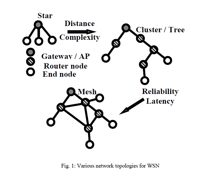
| Network topology is the layout pattern of interconnections of the various elements (links / router nodes etc.) of a computer network. WSN use several network topologies to coordinate with gateway, end nodes and router nodes. Router nodes are similar to end nodes, which can acquire data to be measured and can also pass data from other nodes. Various network topologies for WSN are shown in the Fig. 1. |
| The first and most basic type of topology is the star topology, in which each node maintains a single, direct communication path with the gateway. This topology is simple but restricts the overall distance that a network can achieve. To increase the distance a network can cover, one can implement a cluster or tree topology. In cluster architecture, each node maintains a single communication path to the gateway but can use other nodes to route its data along that path. The drawback of this topology is that the nodes that depend on the router lose their communication paths to the gateway if the disconnection of router node exists. |
| In mesh network topology router disconnection issue is solved by using redundant communication paths to increase system reliability. In this topology, nodes maintain multiple communication path routes back to the gateway. Whenever one router node goes down, the network automatically route data through another path. Mesh topology in spite of very reliable topology suffer from an increase in network latency. This is because data must go through multiple hops before arriving at the gateway. The design criteria and requirements of sensor networks differ from application to application. |
| The rest of the paper is organized with block diagram description, software, results and conclusion. |
 |
BLOCK DIAGRAM DESCRIPTION |
| Fig.2. shows the block schematic of an established wireless sensor temperature monitoring system in a two storied building consisting of wireless sensor nodes and Personal Computer (PC). |
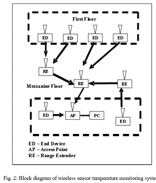 |
| In this work, the wireless sensor nodes which are configured to sense and transmit the temperature are designated as End Devices (ED). The sensor node attached to the PC through USB port to receive the values regarding temperature measured by various EDs is configured as Access Point (AP). Also, the sensor nodes configured to receive the data sent from the ED, and retransmit it to the nearby node or the AP to increase the radio range for efficient communication are designated as Range Extender (RE). |
SENSOR NODE (SN): |
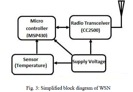
| The Sensor Node is a device that can communicate via radio link. The task of the sensor nodes is to gather information about physical or environmental conditions and transmit (i.e., sink). The block diagram of WSN node is shown Fig. 3. WSN nodes/motes typically comprises of sensor, microcontroller and transceiver. |
| A. Sensor: |
| In this work, it is aimed at monitoring temperature of various rooms of specified infrastructure. An in-built temperature sensor of the microcontroller MSP430 is used to sense the temperature of the surrounding environment. |
| B. Microcontroller (MSP 430): |
| The temperature sensed by the sensor is then processed using microcontroller MSP430. The MSP430 is a 40 pin ultra-low power microcontroller which incorporates a 16-bit RISC CPU, which has a flexible clock system that interconnects using a von-Neumann common memory address and data bus. MSP stands for “Mixed Signal Processing” which refers to the integration of digital and analog circuitry used in the microcontroller. The MSP430 has one active mode and five software selectable low-power modes of operation, each mode used for specific application. |
 |
| C. Radio Transceiver (CC 2500): |
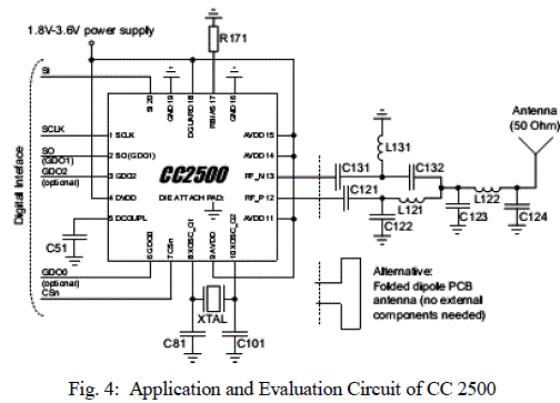
| The processed data from microcontroller is then communicated using radio transceiver CC 2500. The CC 2500 is a low-cost 2.4 GHz transceiver designed for very low-power wireless applications. The CC 2500 is integrated with a highly configurable baseband modem. The modem supports various modulation formats and has a configurable data rate up to 500Kbaud. CC 2500 provides extensive hardware support for packet handling, data buffering, burst transmissions, clear channel assessment, link quality indication and wake-on-radio. Typical evaluation circuit for CC2500 is shown in the Fig. 4 [11]. |
 |
| D. Supply voltage: |
| Two AAA batteries each of voltage 1.5V are used for powering the wireless sensor node. |
| ACCESS POINT (AP): |
| The Texas Instruments EZ430-RF2500 wireless sensor node is programmed to serve as an access point using IAR workbench software. AP is programmed to receive the temperature values measured at various end devices at regular intervals of time along with temperature measurement at the AP. The sensed temperature of various EDs and AP are sent to PC via USB port. |
| END DEVICES (ED): |
| The Texas Instruments EZ430-RF2500T wireless sensor nodes are programmed as End Devices and assigned unique IDs. Each ED is programmed to sense the temperature of the surrounding environment and transmit the same periodically along with its ID in prescribed format. |
| RANGE EXTENDER (RE): |
| In order to enhance the radio range of EDs, the EZ430-RF2500T wireless sensor nodes are programmed as REs. Each RE is programmed to receive the data guided from the ED and retransmit it to the nearby RE or the AP periodically. |
SOFTWARE |
| IAR EMBEDDED WORKBENCH: |
| The IAR Embedded Workbench of MSP430 microcontrollers are an Integrated Development Environment (IDE) for building and debugging embedded applications. The WSN testbed will provide a way for testing, monitoring, debugging different projects, evaluating possible applications and supporting related experiments. The program has been developed using „CâÃâ¬ÃŸ and IAR workbench software to implement WSN testbed to monitor the temperature of infrastructure with well-organized programming of EDs, REs and AP respectively. |
| SIMPLICITI NETWORK PROTOCOL: |
| The SimpliciTI protocol is used as a protocol for communication between sensor nodes in the present work. SimpliciTI is a proprietary, low-power radio-frequency (RF) protocol targeting simple, small RF networks. The protocol runs on TI's MSP430 ultra-low-power microcontrollers and multiple RF transceivers. Small, low-power RF networks typically contain battery-operated devices, and these devices or nodes are limited for exhibiting communication with each other. With the SimpliciTI network protocol, MCU resource requirements are minimal, resulting in lower system cost for low-power RF networks. The SimpliciTI network protocol supports end devices in a peer-to-peer network topology, an access point is used to store and forward messages, and range extenders to extend the range of the network. |
| CONFIGURATION OF END DEVICE: |
| The EZ430-RF2500T wireless sensor node is used as ED by using the inbuilt temperature sensor to sense the temperature of the surrounding atmosphere. As a part of the initialization procedure, EDs are assigned with 2-byte device ID and the device ID is stored into flash memory for reuse on system. After initialization process, the ED searches for an AP directly or through RE in order to connect to a network. Two LEDs (green and red) are made to toggle during the process of searching. Upon discovery of an AP, the ED establishes a network link, flashing the red LED as an indication. Once connected to the network, all LEDs are turned off and the ED defaults to low power mode (sleep mode). The ED wakes up once in a second toggling the green LED indicating active. In active mode, the ED samples its ambient temperature and battery voltage, transmits the measured data and goes to the sleep mode. |
| CONFIGURATION OF RANGE EXTENDER: |
| The EZ430-RF2500T wireless sensors are used as REs to enhance the radio range of EDs to have efficient communication with AP. As a part of the initialization procedure, each RE is assigned with 2-byte device ID and is stored into flash memory for reuse on system. This node wakes up on RF interrupt, receives the data transmitted by ED/RE and verifies and transmit if data belongs to the established path, otherwise it goes to a sleep mode. |
| CONFIGURATION OF ACCESS POINT: |
| The EZ430-RF2500 wireless sensor node is programmed as an AP. The AP is initialized as a network hub. Upon initialization, the AP uses the internal temperature sensor to measure the ambient temperature once per second for transmission to the PC. In addition, the AP continuously listens for new EDs joining the network and also EDs that have already joined. Two LEDs have been used to indicate these two transactions in the network: a red LED indicating the transmission of the AP's measurements to the PC via com port; a green LED indicating the receipt of a data packet from one of the network ED/REs and communicates to the PC via USB port. |
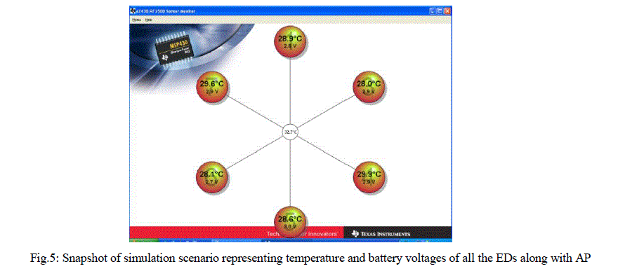
| Graphic User Interface (GUI) based software for the PC has been used to receive the data sent by AP via USB and display the temperature and voltages measured by the end devices using GUI (Fig.5) and recorded using GUI terminal. |
RESULTS |
| The wireless sensor temperature monitoring system has been established using six EDs, three REs and one AP respectively. The snapshot of recorded temperature and voltage values of various EDs is shown in Fig.5. |
 |
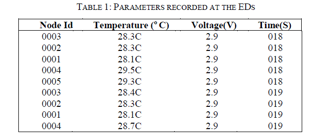
| Table.1 lists the readings recorded at the monitor using sensor monitoring software and Terminal software. In this work, four parameters are selected for monitoring the ED namely, node id, sensed temperature, available voltage at the node and the received time. |
 |
CONCLUSION |
| The wireless sensor temperature monitoring system is established using Texas Instruments wireless sensor nodes in a two storied building. The temperature in the various rooms is monitored and recorded. |
ACKNOWLEDGMENT |
| The authors would like to thank UGC for sanctioning the funds under major research project. |
| Authors (Subramanya Bhat and Jyothi) would like to thank the management of BHS Higher Education Society, Bangalore for allowing them to pursue research. |
References |
|