ISSN ONLINE(2319-8753)PRINT(2347-6710)
ISSN ONLINE(2319-8753)PRINT(2347-6710)
| A. K. Gupta1, P. Bharadwaj2, S. Sahgal3, P. M. Pradhan4 Student, Department of Mechanical Engineering, Sikkim Manipal Institute of Technology, East Sikkim-737132, India1,2,3 Assistant Professor, Department of Mechanical Engineering, Sikkim Manipal Institute of Technology, East Sikkim-737132, India4 |
| Related article at Pubmed, Scholar Google |
Visit for more related articles at International Journal of Innovative Research in Science, Engineering and Technology
This paper presents the investigation, design and fabrication of blanking of thin sheet (0.1-2 mm) of different sheet material. The blank diameter is considered as 10 mm. The study helped to evaluate the influence of tool clearance, burr formation, sheet thickness, punch/die size and blanking layout on the sheet deformation. The punch load variation with tool travel and stress distribution in the sheet has been obtained. The results indicate that a reduction in the tool clearance increases the blanking load and formation of burr increasing or decreasing at different pressure. The objective of this paper is to study the behaviour of punch and formation of burr.
Keywords |
| Blanking, Burr formation, Sheet thickness, Punch load variation, Tool travel |
INTRODUCTION |
| The pneumatic press makes an important contribution to the output of engineering work shops and is indispensable for the cheap production of large quantity of similar articles when the type of articles concerned is suited of this method of production. A pneumatic press utilizes a compressed air source to control operation of piston for high pressure to obtain desire component by using press tools. The press includes a piston operated by the compressed air source to drive a piston rod to operate the press. This pneumatic press is suitable for small press tool works. It works on the principal of compressed air. A compressor plant, pipe lines control valve, drive-members and related auxiliary application. The air is compressed in an air compressor and for the compressor plant, the flow medium is transmitted to the pneumatic system, it is of vital important that the pressure drop between generation and consumption of compressed air is kept very low, it has been seen that pipeline fittings and joints are mostly responsible for drop in pressure, if any in pneumatic system. |
| In a blanking or punching operation, the sheet gets deformed gradually during the forward punch stroke. At times, there is a much localized plastic deformation near the punch and die edges. At a certain stage of the punch travel, this localized deformation gives way to origination of cracks. With a further forward punch travel, these tool edge cracks propagate through the sheet thickness leading to complete separation. J. Gresham, W. Cantwell, M.J. Cardew Hall, P. Compston, S. Kalyanasundaram [1], experimentally found that blank-holder force has a significant effect on the failure mode of the metal–composite system with lower forces resulting in wrinkling as the dominate mode and higher forces resulting in splitting and fracture. A. A. Ambekar, S. K. Maiti, U. P. Singh, P. P. Date, K. Narasimhan [2], showed the influence of various process parameters on sheet metal blanking. Most machining operations do not often produce smooth or well-finished edges on parts. Instead, parts will most likely end up exhibiting ragged, protruding, sometimes hardened, material along edges, known as burrs. Burr formation affects work piece accuracy and quality in several ways; dimensional distortion on part edge, challenges to assembly and handling caused by burrs in sensitive locations on the work piece and damage done to the work surface from the deformation associated with burr formation. A typical burr formed on a metal component due to the exit of a cutting edge can range in shape and size from small and uniform (as in a “knife burr”) to rather large, non-uniform in shape and many millimetres in length. D. Dornfeld and S. Min [3] explained the burrs in conventional machining, process planning for burr minimization as well as micromachining applications. Prof. T. Z. Quazi, R. S. Shaikh [4] discussed the effect of potential parameters influencing the blanking process. |
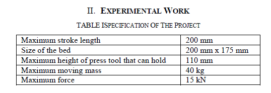 |
| A. Design and development |
| The design is either to formulate a plan for the satisfaction of a special need or to solve a problem. If the plan result in the creation of something having a physical reality, then the product must be functional, safe, reliable, competitive, usable, manufacturable and marketable. A design imperative can be expressed as follows: |
| ïÃâ÷ Invent alternate solution. |
| ïÃâ÷ Through analysis and test, simulate and predict the performance of each alternative, retain satisfactory alternative, and discard unsatisfactory ones. |
| ïÃâ÷ Choose the best satisfactory alternative discovered as an approximation to optimality. |
| ïÃâ÷ Implement the design. |
| B. Design considerations |
| Sometimes the strength required of an element in a system is an important factor in determination of the geometry and the dimension of the element. In such a situation we say that strength is an important design consideration. When we use the expressions design consideration, we are referring to some characteristic which influence the design of the element or perhaps, the entire system. Usually quite a number of such characteristics are taken for consideration in a given design situation, many of the important ones are follows- Strength/Stress, Distortion/Deflection/Stiffness, Wear, Corrosion, Safety, Usability, Utility, Cost, Processing, Weight, Life, Noise, Shape, Size, Control, Thermal properties, Surface. |
 |
| ïÃâ÷ Top plates and cylinder tightened with nut and bolts. |
| ïÃâ÷ U-channel and top plates welded by electric arc welding. Type of joint is lap joint. |
| ïÃâ÷ Piston rod and tool holding plates are welded by electric arc welding. Type of joint is single U-butt joint. |
| ïÃâ÷ U-channel and base plate welded by electric arc welding. Type of joint is lap joint. |
| ïÃâ÷ Slotted plate and base plate is tightened with L-N screw. |
| C. Procedure for material selection |
| The first step in any material selection problem is to define the needs of product. Without prior basis about material or method of fabrication, the engineer should develop a clear picture of all the characteristic necessary for this part to adequately perform its intended function. These requirements will fail into three major areas- |
| ïÃâ÷ Shape or geometry considerations |
| ïÃâ÷ Property requirement |
| ïÃâ÷ Manufacturing concerns |
III. CALCULATIONS |
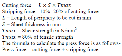
| Cutting force is the force which has to act on the stock material in order to cut the blank or slug. This determines the capacity of the press to be used for particular tool. The first step in establishing the cutting force is to determine the cut length area for straight cuts are performed in the shearing and some cut off operations, the area to be cut is found by multiplying the length of cut by stock thickness. |
 |
| A. Force calculation |
 |
| Calculation for specification of the double acting cylinder in this project:- We know the force required = 14000 N Working pressure =12 bar To find the Bore diameter of the cylinder we use the following formula:- |
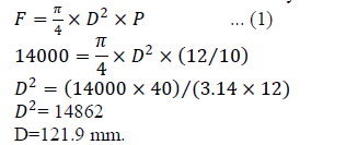 |
| According to the formula bore diameter of the cylinder is = 121.9mm As per the standards bore diameter = 125 mm According to the bore diameter, Piston rod diameter is= 32mm Stroke length=200mm |
| B. Cylinder thrust |
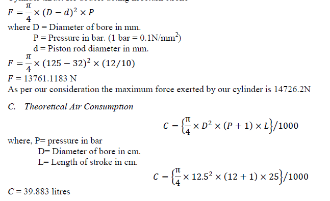
| Cylinder thrust for double acting in forward stroke - |
 |
| Cylinder thrust for double acting in return stroke - |
 |
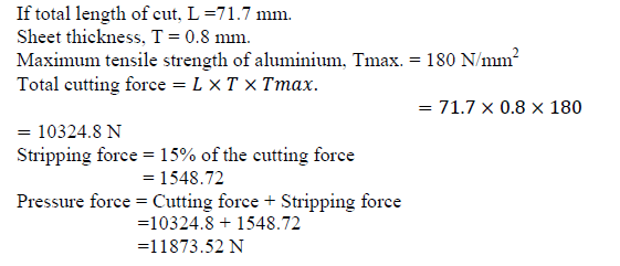
| D. Sample calculation for aluminium |
 |
 |
| As per our consideration we vary the thickness and length of cut and we observe that the length of cut should be less than 73mm. and thickness should less than 1mm. |
| E. Sample calculation for plastic If total length of cut L = 71.7 mm. Sheet thickness T = 1mm. Maximum tensile strength of plastic,Tmax. = 90N/mm2 Total cutting force= 6453 N Stripping force = 967.95 Pressure force = Cutting force + Stripping force = 6453 + 967.95 = 7420.95 N |
 |
| As per our consideration we vary the thickness and length of cut and we observe that the length of cut should less than 72mm and thickness should less than 2.1mm. |
| F. Sample calculation for G.I. sheet If total length of cut, L = 71.7mm. Sheet thickness, T = 0.5mm. Maximum tensile strength of G.I. sheet, Tmax. = 300N/mm2 Total cutting force =10755 N Stripping force = 1613.25 Pressure force = 10755 + 1613.25 = 12368.25 N |
 |
| As per our consideration we vary the thickness and length of cut and we observed that the length of cut should be less than 72mm and thickness should be less than 0.6 mm. |
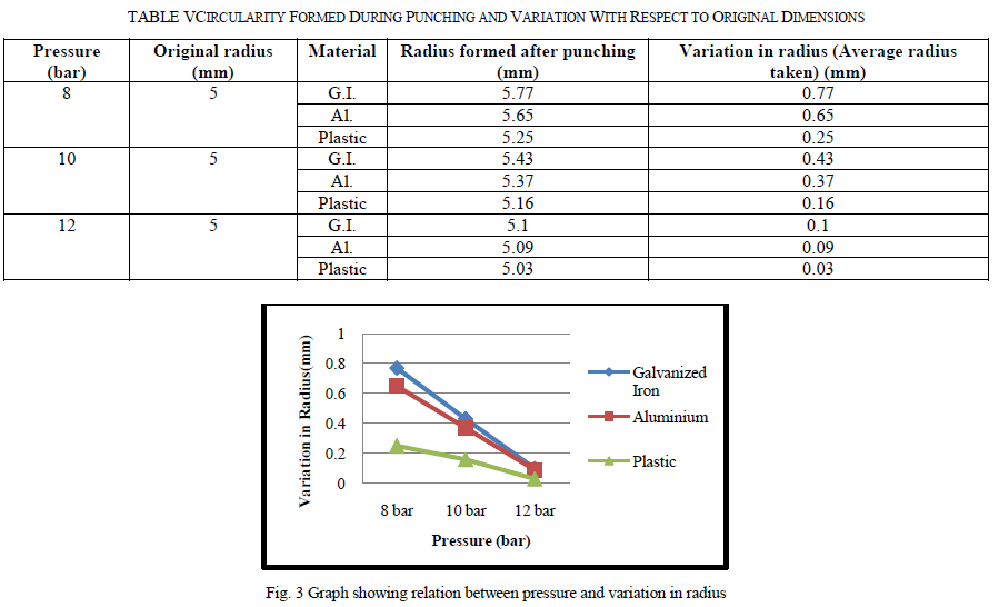 |
| The above graph indicates the relation between pressure and variation in radius. As per the analysis carried on sheets of Galvanized Iron, Aluminium and plastic it was found that as the pressure varies from 8 bar to 12 bar ,the variation of radius decreased with respect to the material and even it was found that the variation of Plastic material was lesser in all different values for pressure. So, if the pressure will be high then rapid cutting/blanking takes place and good quality of component is produced with less variation in radius. |
 |
 |
| The variation in dimension with respect to pressure was obtained as per the result analysis and it was concluded that the variation of dimension was lesser for higher values of pressure for all the three materials. As the variation in dimension is proportional to the straightness therefore we conclude that higher the pressure more will be the straightness and lesser will be the variation in dimension. |
 |
 |
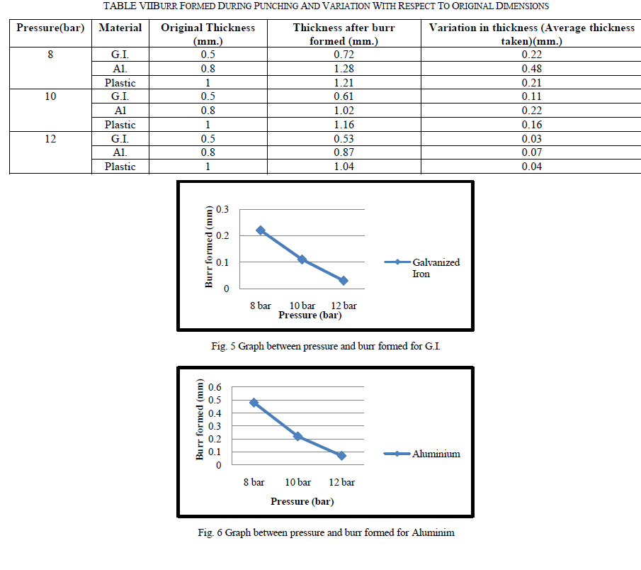
| As the investigation was done in between various material with varying thickness and varying pressure, it was found that higher the pressure, lesser will be the burr formed and even it was seen that in plastic material the burr formation was decreased to higher extent as compared to Aluminium and Galvanized Iron. |
IV. CONCLUSION |
| After experimental investigation and fabrication of pneumatic punch it was concluded that: |
| 1) Circularity of various material sheets punched is proportional to the blanking pressure and further investigation revealed that the circularity embed on a plastic sheet material is more favorable than Aluminium and Galvanized Iron as the ability to resist same pressure is less in plastic material comparable to Aluminium and Galvanized Iron . |
| 2) As per the graphs obtained between burr formation and pressure for Galvanized Iron, Aluminium, and Plastic in fig no. 5, 6, 7 respectively, we observe that burr formation is proportional to the pressure applied. So, graphically we see that less burr is formed in plastic as compared to Galvanized Iron and Aluminium. |
| 3) The experimental investigation of the blanking process makes it possible to study the effects of process parameters such as the material type, the thickness of the sheet and their interactions on the geometry of the sheared edge especially the burrs height. As the result and graph obtained above shows that higher the pressure, lesser will be the burr formation and the burr formation of Plastic material is lesser as compared to Galvanized Iron and Aluminium. |
References |
|