ISSN ONLINE(2319-8753)PRINT(2347-6710)
ISSN ONLINE(2319-8753)PRINT(2347-6710)
Dr B.Venkataraman 1, Gokul Raj 2
|
| Related article at Pubmed, Scholar Google |
Visit for more related articles at International Journal of Innovative Research in Science, Engineering and Technology
An internal combustion engine produces excessive exhaust noise. A good exhaust system should control and keep the exhaust noise within the passable limit. Passive noise control techniques are employed to control the exhaust noises. Mufflers acts as a passive noise control elements in an exhaust system which attenuates noise by reflecting the sound wave and cancels it by destructive interferences and by absorbing the sound and dissipate into heat using absorptive materials .The muffler using absorptive materials for attenuating noise can cover a wide range of higher frequencies creating less back pressure while a reflection type muffler works well in lower and mid range frequencies but produces higher back pressure. This papers discusses the experimental results and performance evaluation of both absorption and reflective mufflers which are calculated by sound transmission loss (STL) experiment technique .
Keywords |
| Passive noise control, Reflection, Absorption, Frequency, Internal Combustion Engine. |
INTRODUCTION |
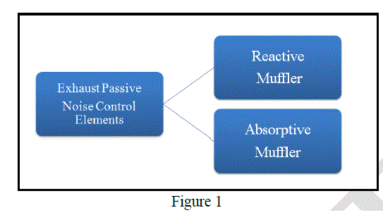
| The main sources of noise in an internal combustion engine are the exhaust noises. The exhaust noise is the most dominant noise source out of all engine noises [1]. To reduce this unwanted noise, passive noise control elements such as mufflers are usually used, refer figure 1. These mufflers have to attenuate noise for a wide range of engine firing frequency and its harmonics [2]. The engine firing frequency can be determined by using equation (1). The reactive muffler can be designed to attenuate noise for lower frequencies less than 800 Hz and the absorption mufflers are good in higher frequencies generally above 600 Hz which also refine the sound quality of the exhaust. Various studies are done on muffler design parameters evaluating performance [3]. One of the design parameter for muffler is the sound transmission loss technique .a detailed study has being done on this experiment method by Z.Tao & A.F.Seybert. et al [4]. In their study it is being found that two source STL test method is the best method to determine the STL of the muffler which also gives accurate result. so for the muffler performance evaluation two source test method is employed. |
| Engine firing frequency = Number of engine cylinders x Engine RPM / 120 -------------- (1) |
| Example: For an inline 8 cylinder automotive engine running at 6000 RPM will have the firing frequency of 120 Hz and its harmonic frequency will go up to 960 Hz, in addition to that turbo charger noises may go up to 3000 Hz and above. So this clearly shows that an automotive exhaust muffler have to attenuate noise more than 3000 Hz. In the experiment the STL will be measured from 50 Hz to 5000 Hz. |
 |
MATERIALS AND METHOD |
| Sound Transmission loss (STL) is an important parameter for designing a muffler. Sound Transmission loss specifies and determines acoustic performance property of a muffler [5]. It is defined as the ratio between the incident sound energy entering the muffler and to the transmitted sound energy leaving the downstream of the muffler where the end is an anechoic termination condition. Sound Transmission loss can be expressed in equation (2) & (3). |
| STL = 10 Log10 Wi / Wt -------------------- (2) |
| STL = 20 Log10 Pi / Pt -------------------- (3) |
| Where |
| Wi refers to the incident sound energy. |
| Wt refers to the transmitted sound energy. |
| Pi refers to the incident pressure amplitude. |
| Pt refers to the transmitted pressure amplitude. |
PASSIVE NOISE CONTROL TYPES |
| A muffler is a passive noise control element in an automobile exhaust system that is designed to reduce the amount of noise that an engine produces due to combustion [6]. Performance of mufflers is not only to reduce sound levels, but with reduced back pressure. Back pressure is created in the exhaust line because of restrictions of exhaust gases by muffler in the exhaust line [7]. The back pressure must be minimal because they help to reduce the work done by the engine components, thereby increasing the performance of the engine.Muffler is a key part of the exhaust system which attenuates the unpleasant noise emitted by the engine after the combustion during the exhaust stroke. |
REACTIVE TYPE MUFFLER |
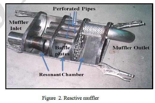 |
| The reactive muffler consists of resonant chambers separated by series of baffle plates and pipes as shown in figure 2. The gas flow from the engine is directed by pipes of different lengths and with perforations. It distributes the exhaust gases in to the resonant chambers .the reactive muffler works by the principle of Helmholtz principle. The muffler reflects the pressure wave 180º out of phase back to the noise source which eventually cancels it by destructive interference. The reactive muffler works well in lower and mid range engine firing and harmonic frequencies the acoustic performance of reactive muffler is high in the frequency range of 30 to 600 Hz. the exhaust gases expands in the muffler chamber and thus reduces its pressure amplitude .the reactive muffler also reduces the high velocity gases to slow down and reduces the flow oriented noises, the only disadvantage of using reactive muffler is it creates high back pressure .Proper design of perforation in baffle plates and pipes and selection of pipe diameter will control the back pressure to the optimum. The volume of the muffler is selected based on the size of the engine generally the muffler volume should to 10 to 12 times the size of the engine can reduce the pressure amplitude effectively [8]. The advantage of reactive muffler is the life time of the system will be longer since there are no non degradable materials inside it. Proper selection of sheet metal materials will have a longer run without rusting. |
ABSORPTIVE TYPE MUFFLER |
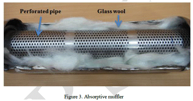 |
| The absorptive muffler consists of a perforated pipe covered by noise absorbing glass wool as shown in figure 3. The tube is perforated so that some part of the pressure wave goes through the perforation through the noise absorbing glass wool. The glass wool is a noise dampening material which is fibrous in nature and is protected from the surrounding by an auxiliary cover made of a steel metal sheet. The glass wool can with stand heat more than 950 º C thus it is suitable for exhaust application with high temperature [9].The absorption muffler as the name suggests absorbs the noise through its fibrous glass wool where the noises dissipate as heat due to the friction. The heat then transfers to the outer shell and loses its intensity thus reducing the noises of the exhaust. The absorption muffler generally consists of straight through pipes so the exhaust gases will have minimal restriction inside the pipe creating very less back pressure compared to a reflective muffler. But the straight through absorption muffler are effective only in higher frequencies i.e. in the range of above 600 Hz and above. This muffler works well in higher engine RPM with higher frequency and its harmonics [10]. Below 600 Hz the noise reduction performance gradually reduces in absorption muffler. The amount of glass wool is selected based on the size of the outer shell where its dimensions are solely selected due to the under body space of the vehicles chassis. The glass wool quantity is basically selected by its packing density a good muffler with greater noise performance will have a packing density between 80 to 120 kg//m3. The performance of the muffler reduces if the packing density is below 80 kg//m3 and there will be no improvement in absorption quality if it is above 120 kg/m3.The perforation size in the pipe should not be above 3mm diameter because the fibrous glass wool may escape through the holes to the atmosphere by the high velocity gas flows through the pipe leading to reducing in mufflers noise attenuating performance. A disadvantage in using absorption muffler is the glass wool may deteriorate due to heat in the longer run. In this paper STL experiment is carried out and the performance of absorption muffler is analysed and discussed in detail. |
EXPERIMENTAL INVESTIGATION |
| The experimental set up of STL is shown in figure 4a, it consists of an impedance tube with four microphones, two each in upstream and downstream of the impedance tube respectively. The front end of the tube is connected to the speaker which acts as the sound driver which gets the signal from the noise generator through power amplifier. The four microphones are connected to the STL analyser. |
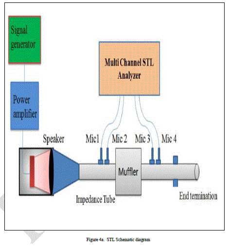 |
| The muffler is fixed between the two impedance tubes. The inlet of the muffler is connected to the microphone 1 & 2 side where as the out let of the muffler is connected to the Microphone 3 & 4 side .The impedance tube end acts as an anechoic termination. During the first measurement the speaker is kept at the upstream impedance tube and during the second measurement the speaker is kept in the reverse i.e. at the downstream end of the impedance tube as second source for calculating the transmission loss of the muffler. The experimental setup is shown in figure 4b. The test setup is based on the ASTEM 1051[11] standard. |
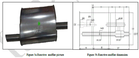 |
| In this experiment two passive noise reduction elements 1) reactive muffler 2) absorption muffler are subjected to STL measurement. After that the performance evaluation is done for both the mufflers. The reactive muffler, figure 5a, has two baffle plates and 3 perforated pipes and there are 3 resonant chambers for controling low frequency noises.The internal dimensions of the reactine muffler is shown in figure 5b. |
 |
| The absorption muffler, figure 5c, consists of a straight through perforated pipe surounded by glass wool .The inlet and out let of the mufflers are connected to the up steam and down stream of the impedance respectively. The internal dimensions of the absorptive muffler is shown in figure 5d. |
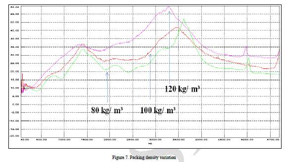 |
| The absorption muffler has the glass wool packing density of 120 kg/ m³. For finding the effect of packing density it is reduced to 100 & 80 kg/ m³ and sound transmission loss measurement is performed for all three variants. The experimental results are then analysed for their performance. |
EXPERIMENTAL RESULTS |
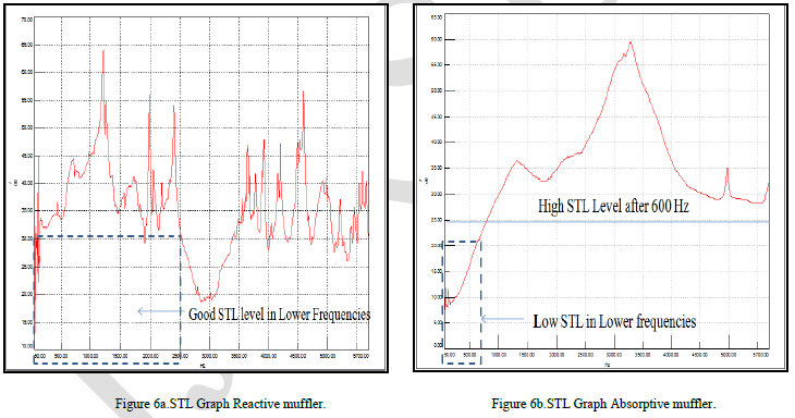 |
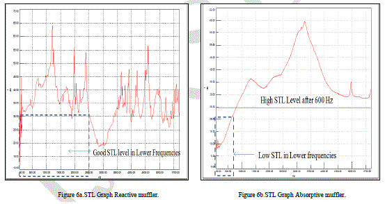
| The sound transmission loss of the reactive muffler is shown in figure 6a and it good in lower frequencies and it is above 30 dB from 50 Hz onwards. The STL starts detorating in the higher frequency from 2500 Hz ,where as for absoprtive muffler STL result is above 30 dB from 1000 Hz onwards. It is high throughout the higher frequencies.But in the lower frequencies the STL is very less .Below 600 Hz the absorption material does not control the low frequency noise . With this results it is found that the reactive muffler works well at lower frequencies and the absortive muffler is effective only in higher frequencies. |
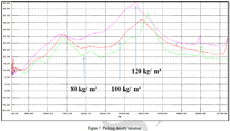 |
| Further the the STL result of absorptive muffler in which the packing densities of glasswool is reduced from 100 and 80 kg/ m³ shows that the result of 80 kg/ m³ has the lowest STL value through out all the frequencies. The variant with 100 kg/ m³ has a better STL value than 80 kg/ m³ but still it is lower than 120 kg/ m³ glass wool variant which is eventually has the highest STL value of all the variants. Refer figure 7. |
BACK PRESSURE VALUE |
| The back pressure is measured for both type of mufflers in a gas flow test rig which produces the flow rate of 250 kg/hr at 600º C and it is maintained for both the measurements. The measured back pressure values are shown in table 1. |
 |
| The result shows that reactive muffler has the highest back pressure value of 120 mbar for the given gas flow and temperature condition. Whereas the absorptive muffler produces only less back pressure 20 mbar for the same condition. This is because there is very less restriction by the straight through pipe in the absorptive muffler whereas the reactive muffler has lot of restrictions by baffle plates and pipes which leads to higher back pressure. |
CONCLUSION |
| By evaluating the experiment results the paper concludes that both passive noise reduction components are good for exhaust noise control at their designed frequency ranges. Reactive muffler has better sound transmission loss in lower and mid range frequencies and deteriorates in higher frequencies where as a absorptive muffler has high STL level in higher frequencies .the STL performance of absorptive muffler reduces below 600 Hz also the glass wool packing density of 120 kg/ m³ produces highest sound transmission loss. Due to high gas restrictions the back pressure value of reactive muffler is high compared to straight through absorptive muffler which has lower gas restriction. An effective exhaust system may combine these two types of mufflers for higher noise reduction in all engine operating frequencies. |
References |
|