ISSN ONLINE(2319-8753)PRINT(2347-6710)
ISSN ONLINE(2319-8753)PRINT(2347-6710)
AravindKaruppaiah.C1, Ganesh.S1, Dileepan.T1, Jayabharathi.S2
|
| Related article at Pubmed, Scholar Google |
Visit for more related articles at International Journal of Innovative Research in Science, Engineering and Technology
The Thermo Electric Generator can be used to produce power using the exhaust waste heat from IC engines (automobiles). This power can be used to charge the battery of automobiles (two-wheelers). This system of charging the battery reduces the fuel consumption and battery life is also increased. The project describes the design and analysis of TEG with the material used. The factors affecting the efficiency of TEG are studied. The properties of the material, efficiency of TEG and the heat transfer in TEG are also studied using ANSYS. The objective of the project is to produce power from the waste sources. To reduce the heat let into the atmosphere. To reduce the fuel consumption of automobiles. To increase the life of the battery used in automobiles
Keywords |
| TEG, battery, fuel consumption |
INTRODUCTION |
| A. Thermo Electric Generator |
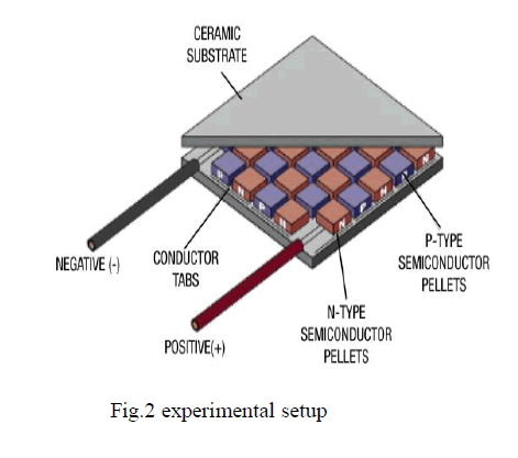
| The thermo electric generator (TEG) is the system used to generate power from low temperatures that is less than 1000K as heat input. It is best method for recovery of exhaust heat. It can be used in many fields such as automobiles, boilers wood stoves etc. The efficiency of a TEG depends on the thermo electric materials. The main research of the world is to use the renewable energy. The main advantage of TEG is that it uses green energy. The TEG is mainly based on the principle of Seebeck effect. The efficiency of a thermo electric generator is about 5%. A heat source provides the high temperature, and the heat flows through a thermoelectric converter to a heat sink, which is maintained at a temperature below that of the source. The temperature differential across the converter produces direct current (DC) to a load (RL) having a terminal voltage (V) and a terminal current (I). There is no intermediate energy conversion process. For this reason, thermoelectric power generation is classified as direct power conversion. The amount of electrical power generated is given by I2RL, or VI. |
| A unique aspect of thermoelectric energy conversion is that the direction of energy flow is reversible. So, for instance, if the load resistor is removed and a DC power supply is substituted, the thermoelectric device can be used to draw heat from the “heat source” element and lower its temperature. In this configuration, the reversed energy-conversion process of thermoelectric devices is invoked, using electrical power to pump heat and produce refrigeration. |
 |
| B. Thermo Electric Material |
| Thermoelectric materials (those which are employed in commercial applications) can be conveniently divided into three groupings based on the temperature range of operation. Alloys based on Bismuth (Bi) in combinations with Antimony (An), Tellurium (Te) or Selenium (Se) are referred to as low temperature materials and can be used at temperatures up to around 450K. The intermediate temperature range - up to around 850K is the regime of materials based on alloys of Lead (Pb) while thermo-elements employed at the highest temperatures are fabricated from SiGe alloys and operate up to 1300K. Although the above mentioned materials still remain the cornerstone for commercial and practical applications in thermoelectric power generation, significant advances have been made in synthesizing new materials and fabricating material structures with improved thermoelectric performance. Efforts have focused primarily on improving the material’s figure-of-merit, and hence the conversion efficiency, by reducing the lattice thermal conductivity. |
| C. Battery Charging System |
| The existing system of charging the battery for automobiles consumes 10 % of the fuel, and hence the efficiency of the engine is reduced. This system is to be replaced by TEG system of charging the battery which is light in weight and battery life also can be increased. |
| FACTORS AFFCTING THE EFFICENCY OF TEG |
| Thermo Electric Material |
| Hot source |
| Cold source |
| Heat transfer |
EXPERIMENTAL SETUP |
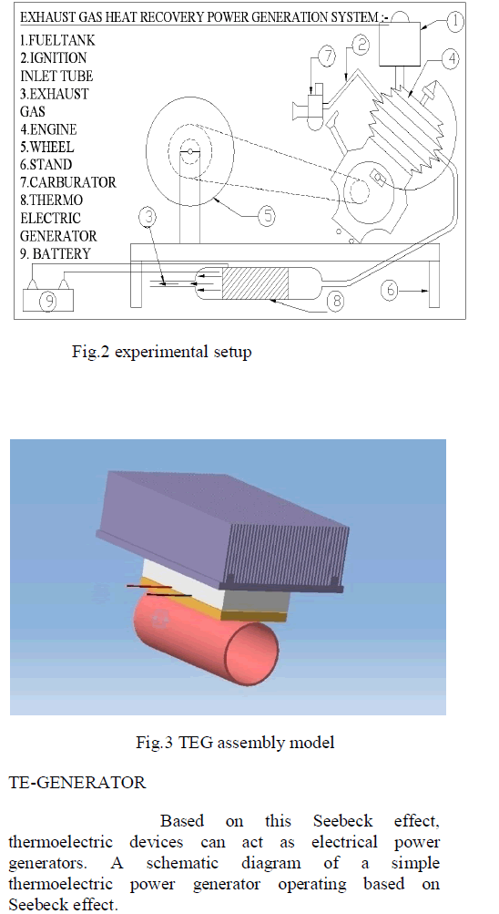
| The experimental setup for testing is shown |
 |
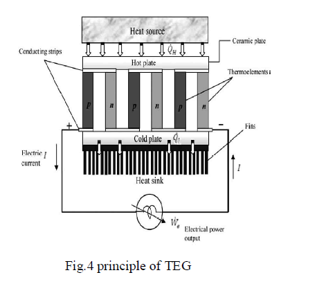 |
| As shown in figure, heat is transferred at a rate of Qhfrom a high-temperature heat source maintained at Th to the hot junction, and it is rejected at a rate of Ql to a lowtemperature sink maintained at Tl from the cold junction. Based on Seebeck effect, the heat supplied at the hot junction causes an electric current to flow in the circuit and electrical power is produced. |
| Using the first-law of thermodynamics (energy conservation principle) the difference between Qh and Ql is the electrical power output we. It should be noted that this power cycle intimately resembles the power cycle of a heat engine (Carnot engine), thus in this respect a thermoelectric power generator can be considered as a unique heat engine. |
| Charge carriers in the materials (electrons in metals, electrons and holes in semiconductors, ions in ionic conductors) will diffuse when one end of a conductor is at a different temperature than the other. Hot carriers diffuse from the hot end to the cold end, since there is a lower density of hot carriers at the cold end of the conductor. Cold carriers diffuse from the cold end to the hot end for the same reason. |
| If the conductor were left to reach equilibrium, this process would result in heat being distributed evenly throughout the conductor. The movement of heat (in the form of hot charge carriers) from one end to the other is called a heat current. As charge carriers are moving, it is also an electrical current. |
| In a system where both ends are kept at a constant temperature relative to each other (a constant heat current flows from one end to the other), there is a constant diffusion of carriers. If the rate of diffusion of hot and cold carriers were equal, there would be no net change in charge. However, the diffusing charges are scattered by impurities, imperfections, and lattice vibrations. If the scattering is energy dependent, the hot and cold carriers will diffuse at different rates. This will create a higher density of carriers at one end of the material, and the distance between the positive and negative charges produces a potential difference; an electrostatic voltage. |
| This electric field, however, will oppose the uneven scattering of carriers, and equilibrium will be reached where the net number of carriers diffusing in one direction is cancelled by the net number of carriers moving in the opposite direction from the electrostatic field. This means the thermo power of a material depends greatly on impurities, imperfections, and structural changes (which often vary themselves with temperature and electric field), and the thermo power of a material is a collection of many different effects. |
THERMO ELECTRIC MATERIAL |
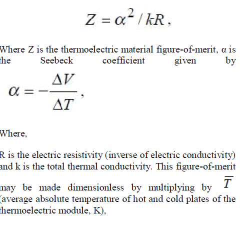
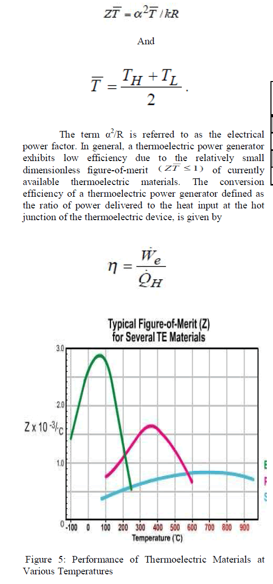
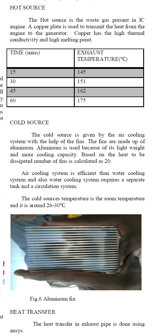
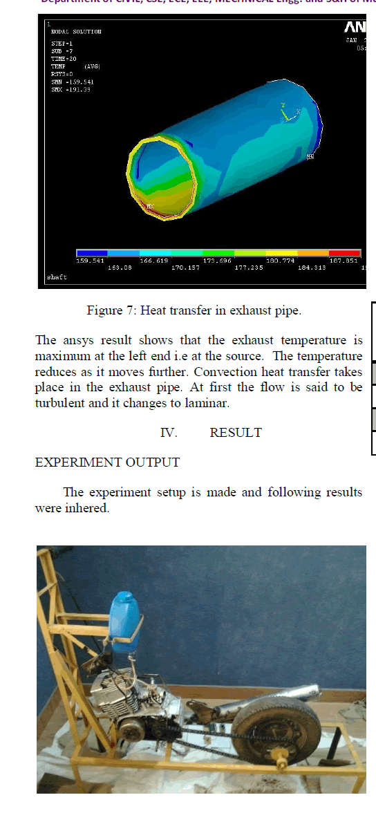
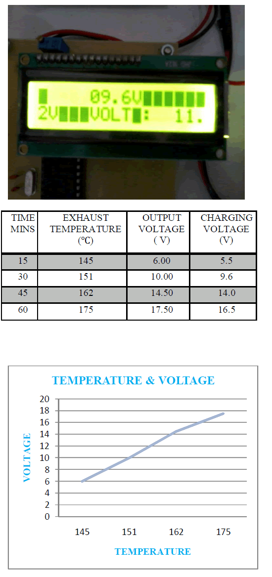
| The thermo electric material used in this project is silicon and germanium. The material is selected on the basis of power factor , figure of merit and melting point.The performance of thermoelectric materials can be expressed as |
 |
 |
 |
 |
 |
 |
ACKNOWLEDGMENT |
| We are very thankful and grateful to our Department Head Dr.K.Velmurugan, Co-ordinator Mr.G.B.M.Mohanraj, and our beloved sister Ms.K. Krishnapriya whose great support, valuable advices, suggestions and tremendous help enabled us in completing our project. They have been a great source of inspiration to us. |
CONCLUSION |
| We conclude that TEG system of charging the battery could reduce the fuel consumption and also battery life used in automobiles could be increased. It is the best method for recovery of waste exhaust heat. The main advantage of TEG is that it produces power from the waste heat source. |
References |
|