Fault diagnosis is an ongoing significant research field due to the constantly increasing need for maintain ability, reliability and safety of industrial plants. The pneumatic actuators are installed in harsh environment: high temperature, pressure, aggressive media and vibration, etc. This influenced the pneumatic actuator predicted life time. The failures in pneumatic actuator cause forces the installation shut down and may also determine the final quality of the product. A fuzzy logic based approach is implemented to detect the external faults such as Actuator vent blockage, Diaphragm leakage and in correct supply pressure. The fuzzy system is able to identify the actuator condition with high accuracy by monitoring five parameters. The parameter selection is based on the committee of DAMADICS (Development and Application of Methods for Actuator Diagnosis in Industrial Control Systems). The Fuzzy Inference Systems were implemented in real time using MATLAB and the results prove that the system can effectively classify all the types of external faults.
Keywords |
| Actuators, Fault Detection and Diagnosis, Fault Detection and Isolation, Fuzzy Logic System |
INTRODUCTION |
| A common element in the modem industries is nothing but the pneumatic actuator and it is used to control the fluid and
gas flow. Presence of fault in these actuators is accountable for some changes in the operating conditions, which create
disturbances in the overall process. In consequence of a deviation of process output and in sometime a severe failure, it
makes an unscheduled process shut down. The rising complexity of process industries as well as the necessity to reduce
the overall manufacturing costs, demands the evolution of appropriate methods not also finding but also attributing
causes to pneumatic actuator failures. Different types of techniques for Fault Detection and Isolation (FDI) of nonlinear
systems were formed and could be applied to pneumatic actuator. In general, the FDI technique monitors some critical,
measurable characteristics or parameters are related to the operation of the plant system [1]. When the measurable
parameters deviate from their normal values, it is affirmed that a fault has occurred. If the critical performance
parameters are properly selected, there is possibility for identifying each fault. The design technique of an effective FDI
system requires that: (i) a method for obtaining performance parameters correlated to the system performances, which
have high information about the faults, and (ii) a decision making technique that identifies the specific fault condition
pertaining to a particular set of measurable parameters [1]. |
| For the past two decades, many numbers of techniques, that proposed different method for the fault diagnosis. Beard
(1971) and Jones (1973) have developed an observer-based fault detection called Beard-Jones Fault Detection Filter
[2 - 3]. Mehra & Peschon (1971) and Willsky & Jones (1974) use statistical approaches to fault diagnosis [3]. Clark,
Fosth & Walton 1975) applied Luenberger observers [4]. Mironovsky (1980) proposed a residual generation scheme
for the purpose of checking on the system input and output over a time limit [5]. Artificial Intelligence researchers
(1980) proposed a fault diagnosis based on First-Order Logic. Frank (1987) introduced observer based method [6] and
Isermann (1991) proposed parity relation method [7] also Basseville and Nikiforov (1993) proposed parameter estimation method [8]. In 1993 Fault Detection and Isolation community was formed based on the classical fault
diagnosis methodologies. The analytical redundancy method was introduced by SAFEPROCESS called Steering
Committee (1991) with IFAC (International Federation of Automatic Control). Hamscher et al. (1992) proposed a
Model-Based Diagnosis (MBD) [9]. Patton et al. (1999; 2000) delivered tutorial on the use intelligence techniques [10].
Recently, hybrid intelligent systems methods are also introduced by Negoita et al. (2005) [11].Right now, Neural
Network based fault detection are introduced by Prabakaran K et al. (2013) using Back Propagation algorithm. |
| In accordance with modern methodologies to solve Fault Diagnosis problems in nonlinear dynamic systems can be
broadly classified into three categories. The first one is a mathematical model based approach. But it is clear that
constructing mathematical models for complex systems are very difficult. Even though a mathematical model is
designed, experimental evaluation of the model is also difficult. This method does not seem to be easy for complex
system. The third method is to use artificial intelligence techniques as fault classifiers to solve Fault Diagnosis
problems [12].This paper has proposed a Sugeno type Fuzzy Inference System to diagnose faults in the Pneumatic
actuator. This approach is a novel method which achieves effective fault diagnosis by the use of a rule based pattern
recognition methodology endowed with on fuzzy algebra and developed to give an alternative mythology for
conventional estimation techniques. |
PNEUMATIC ACTUATOR |
| The most used final control element in the automation industries is the pneumatic actuator control valve. It adjusts the a
flowing fluid, such as water, steam, gas or chemical compounds to compensate for the load variable and keep the
controlled process variable as close to the required input set point[13,19].The input of the actuator is the output of the
process controller (flow or level controller) and the actuator modifies the position of the valve allowing a direct effect
on the primary variable in order to accompany the flow or level set-point[13,19].The internal structure of pneumatic
servo-actuator, which is used as a testing element for fault detection as illustrated in Figure 1. |
| Actuator Main Components: The pneumatic actuator control valve includes three main parts: control valve, springand-
diaphragm pneumatic servo-motor, positioned as shown in the Figure 1. |
| Control Valve: The control valve is a mean used to prevent and/or limit the flow of fluids. Changing the position of
the control valve is done by a servo motor. |
| Spring and Diaphragm Pneumatic Servomotor: It can be defined as a compressible pressure powered device in
which the pressure acts upon the flexible metallic diaphragm, to provide a linear motion to the stem. |
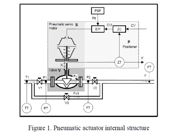 |
| Positioner: The positioner is a device applied to eliminate the pneumatic actuator stem improper positions produced by
the internal sources or external sources such as pressure unbalance, hydrodynamic forces, friction, etc. It consists of an
inner loop with a P controller of a cascade control structure, including the output signal of the outer loop of the flow or
level controller and the inner loop of the position controller [14, 19]. The internal parts of the actuator are indicated in
notation and the measurable parameters are designated as the transmitter. |
Internal Parts of Actuator |
| S -Pneumatic servo-motor |
| V -Control valve |
| P –Positioner |
| ZC -Position P Controller (internal loop Controller) |
| E/P -Electro-Pneumatic Transmitter |
Additional External Parts |
| V1 -Cut-Off Valve |
| V2 -Cut-Off Valve |
| V3 -By-Pass Valve |
| PSP -Positioner Supply Pressure |
| PT -Pressure Transmitter |
| FT -Volume Flow Rate Transmitter |
| TT -Temperature Transmitter |
Basic Measured Physical Parameters |
| CV -External (Level or Flow) Controller Output (%) |
| P1 -Valve Input Pressure (kPa) |
| F -Flow Measurement (m3/h) |
| P2 -Valve Output Pressure (kPa) |
| T1 -Liquid Temperature (°C) |
| X -Rod Displacement (%) |
CONTROL VALVE FAULTS |
| The Manuscripts of DAMADICS project focuses on pneumatic actuators fault detection methodology. DAMADICS
committee has concentrated on the evolution of actuators Fault Detection and Isolation (FDI). The real time FDI
algorithms are applicable in industrial environment [15]. DAMADICS discovered the 19 types of pneumatic actuator
faults which occur in the pneumatic actuator valve during the overall process [16]. |
| The pneumatic actuator faults are classified into the following four categories: General faults/external faults, Control
valve faults, Positioner faults and Pneumatic servo-motor faults. Probably, single actuator faults are observed in
industrial process while multiple faults rarely occur. Referring to Figure.1, it is observed that the measurable
parameters describe the main characteristics of the actuator. When a fault occurs, the measurable parameters would
vary from a normal operating condition. So these measurable parameters enable us to characterize the changes in the
operation of the actuator due to the occurrence of the faults [17]. |
Fault Considered for Diagnosis |
| In real time process plenty of faults may occur in pneumatic actuator. Three commonly occurring faults which are
considered for the fault diagnosis process are |
| Incorrect supply pressure |
| Diaphragm leakage |
| Actuator vent blockage |
Measurable Parameters Considered For Fault Diagnosis |
| The following five measurable parameters are considered for the diagnosis process to identify the three faults which are
approved by the DAMADICS [15, 19]. |
| Rod Displacement (%) |
| Valve Output Pressure (kPa) |
| Valve Input Pressure (kPa) |
| Flow Measurement (m3/h) |
| External (Flow or Level) Controller Output (%) |
SUGENO-TYPE FUZZY INFERENCE SYSTEM |
| Fuzzy logic is used for both fault detection via modelling, and fault isolation via a class of nonlinear systems. Takagi
and Sugeno proposed a new mathematical tool to create the fuzzy model for a fault diagnosis system. This type of
fuzzy models is more accurate than the Mamdani-type models for modelling real time processes. Fuzzy logic is very
often used to perform fault isolation tasks. The relationships between measureable parameters and the faulty states of
the monitored system are expressed by a set of if-then rules. The Sugeno-type models are preferred for this task due to
the transparency offered by using linguistic terms. During the test phase, the measureable parameters presented at the
input of the fuzzy classifier are mapped into the corresponding faulty state using fuzzy inference [18]. |
Fuzzy Modelling of Systems with Faults |
| Takagi and Sugeno (1985) use fuzzy rules, with the general form given by Eq. 1, to build the fuzzy model of a system |
 |
| Where, y is the output of the system whose value is inferred x1, …, xk are input variables of the system, A1, …, Ak
represent fuzzy sets with linear membership functions standing for a fuzzy subspace, in which the rule R can be applied
to reasoning. If the system is described by a set of rules {R / i 1,...n} i having the previous form, and the values of
input variables x1, x2, …, xk are x1 0, x2 0,...,, xk 0, respectively, the output value y is inferred following the next three steps. |
| Step 1: For each Ri, the value yi is computed as follows: |
 |
| Step 2: The truth value of the proposition y=yi is computed as follows: |
 |
| where |*| means the truth value of the proposition *, ^ stands for the min operation, and A (x) =|x is A|, and it represents
the grade of membership of x in A. The value |Ri| is called the confidence level in the i-th rule and is considered to be 1. |
| Step 3: The output y is computed as the average of all yi with the weights |y=yi|, |
 |
Fuzzy Evaluation of Residuals |
| Sugeno-type fuzzy logic for measureable parameters evaluation is used, in order to isolate the faults that are measured.
Let be the set of residuals. Each measureable parameters ri, i=1,…,m, is described by a number of fuzzy sets
{ri1,ri2,…,ris}, whose membership functions are identified using methods like domain expert knowledge. The causal
relationships between the measureable parameters and faults are expressed by if-then rules having a form similar to
equ. 5. |
 |
| The output of the fuzzy classifier is the faulty vector F. The fuzzy inference process will assign to each component Fi,
i=1,…,m, a value between 0 and 1 that indicates the degree with which the normal state (the corresponding component
is F0), or the j-th fault, affects the monitored system, j=1,…,m. If there is the premise that the system can be affected
only by a fault at a time, then the faulty vector contains only one component larger than a preset threshold value, and
whose corresponding faulty state represents the actual state of the monitored system. If multiple faults can affect the
monitored system, then the components of the classifier output, which are larger than a preset threshold, indicate the
faults that occurred in the system [18]. |
HARDWARE DESCRIPTION |
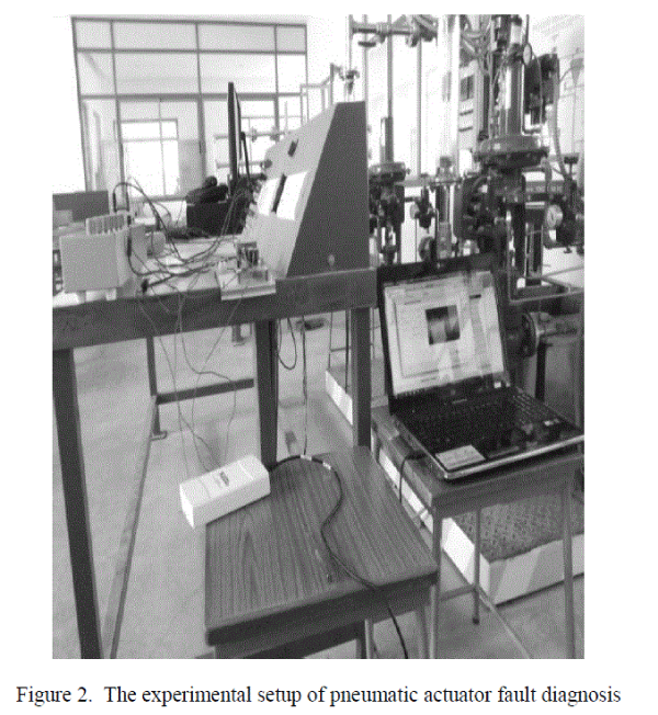
| The pneumatic actuator of normally closed type with positioner is used up for the fault diagnosis. The control signal is
applied to the control valve through the National instrument USB DAQ card. The experimental setup for the fault
diagnosis is shown in the Figure 2. |
 |
| The Table 1 show the appropriate sensors which are employed to measure the five parameters. |
 |
| The data from the sensor are collected in the computer using USB DAQ card. From the hardware setup, 2500 data are
collected to study the changes in each parameter in each faulty condition and as well in normal circumstance. The
gathered data are processed by fuzzy classifier which is developed in MATLAB, to identify the condition of the
pneumatic actuator. |
RESULTS AND DISCUSSION |
| The real time data which were collected at the time of the fault and no fault are fed as input to the fuzzy inference
knowledge base which has some set of rules. The output is compared with known data to calculate the efficiency. The
Number of I/P Membership Function is 5, Number of O/P Membership Function is 4 and the type of Membership
Function is trimf. Table 2 shows the output result of fuzzy logic while running in MATLAB. |
 |
 |
| From the Table 2 it has been identified that the classification error value was only 1.33. It shows that the Fuzzy
Inference System have computational accuracy of 98.99%. The Inference system classifies all the type of faults with the minimum number of rules. In this method 96 rules are created based on the correlation between the measuring
parameters and the faults. |
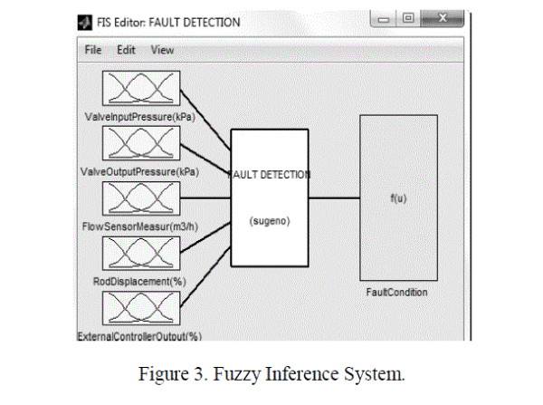
| The Figure 3 shows those five measurable parameters as input and four fault conditions as output including no fault. |
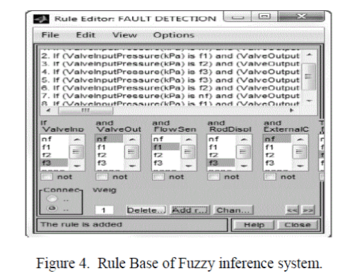 |
| The Figure 4 shows rule base in which 96 fuzzy rules are used to create a fuzzy system. The number of rules is based
on the particular model of the control valve and the type of valve. |
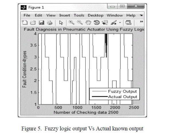 |
| The efficiency of the fuzzy inference system was computed using the know fault data. The fault which is already
known is feed as input to the inference system and the output was compared same. The Figure 5 shows the comparison
plot of fuzzy logic output and known fault. The dark line in the graph represents the Actual known output of four types
of fault conditions and the normal line indicates the Fuzzy logic output. The merging of two plots means that the
inference classifies the fault as correctly. In this method the two plots of fault conditions are merged 99% exactly while
compare with other existing techniques such as Neural Network presented by Prabakaran K et al. (2013). From the
analysis of fuzzy logic output, the Sugeno Type Fuzzy Logic has the perfect ability to diagnosis pneumatic actuator
faults. |
CONCLUSION |
| In this paper, a fuzzy logic approach based fault diagnosis technique for detection and identification of pneumatic
actuator faults was proposed. The faults of interest are various. The specific values of five measurable parameters are
observed to detect the type of fault. For each operating condition, the parameters formed a discriminatory fault
signature that was subsequently learned by fuzzy logic with the goal of successfully detecting and identifying the faults.
The simulation results proved that the fuzzy inference system has a capability to detect and identify the various
magnitudes of the faults with high accuracy. |
References |
- M. Karpenko, N., Sepehri., âÃâ¬ÃÅA Neural Network Based Fault Detection And Identification Scheme For Pneumatic Process Control ValvesâÃâ¬ÃÂ, Proceedings of the 2001 IEEE International symposium on Computational Intelligence in Robotics and Automation July 29 âÃâ¬ÃâAugest 1, pp. 166- 180, 2001.
- Beard R V., âÃâ¬ÃÅFailure accommodation in linear system through selfreorganization (PhD thesis)âÃâ¬ÃÂ, MIT, Massachusetts, USA, pp. 21-30, 1971.
- Jones HL., âÃâ¬ÃÅFailure detection in linear systems (PhD thesis)âÃâ¬ÃÂ, MIT, Massachusetts, USA, pp. 34-80, 1973.
- Clark RN., Fosth DC., Walton WM., âÃâ¬ÃÅDetecting instrument malfunctions in control systemsâÃâ¬ÃÂ, IEEE Transactions on Aerospace and Electronic Systems AES-11, pp. 465-459, 1975.
- Mironovsky LA., âÃâ¬ÃÅFunctional diagnosis of linear dynamic systems âÃâ¬Ãâ a surveyâÃâ¬ÃÂ, Automation Remote Control, 41, pp. 1122- 1125, 1980.
- Frank PM., âÃâ¬ÃÅFault diagnosis in dynamic system via state estimation âÃâ¬Ãâ a survey. In: Systems fault diagnostics, reliability and related knowledge-based approachesâÃâ¬ÃÂ, D. Reidel Press, Dordrecht, Germany, pp. 34-50, 1987.
- Isermann R., âÃâ¬ÃÅFault diagnosis of machine via parameter estimation and knowledge processingâÃâ¬ÃÂ, Tutorial paper. In: Preprints of IFAC/IMACS Symposium SAFEPROCESSâÃâ¬Ãâ¢91, Baden-Baden, Germany, vol. 1, pp. 121 - 145, 1991.
- Basseville M., Nikiforov IV., âÃâ¬ÃÅDetection of abrupt changes: theory and applicationâÃâ¬ÃÂ, Information and System Science, Prentice Hall, New York, pp. 90-95, 1993.
- Hamscher WC., De Kleer J., Console L., âÃâ¬ÃÅReadings in model-based diagnosisâÃâ¬ÃÂ, Morgan Kaufmann, San Mateo, CA, USA, pp. 67-70, 1992.
- Patton RJ., âÃâ¬ÃÅFault tolerant control: the 1997 situation (survey)âÃâ¬ÃÂ, In: Proceedings of the IFAC Symposium SAFEPROCESSâÃâ¬Ãâ¢97, Pergamon, University of Hull, UK, pp. 1029-1039, 1997.
- Negoita M., Neagu D., and Palade V., âÃâ¬ÃÅComputational Intelligence: Engineering of Hybrid SystemsâÃâ¬ÃÂ, Springer-Verlag, pp. 56 -89, 2005.
- M.Karpenko., N.Sepehri.,D.Scuse., âÃâ¬ÃÅDiagnosis of process valve actuator faults using a multilayer neural networkâÃâ¬ÃÂ, Control Engineering Practice 11, pp.1289-1298, 2003.
- DAMADICS Benchmark Definition., Warsaw University of Technology, Institute of Automatic Control and Robotics Team with cooperation with UPC, Preliminary, ver. 1.0 March 17, pp. 01- 50, 2002.
- DAMADICS Benchmark Definition., Warsaw University of Technology, Institute of Automatic Control and Robotics Team with cooperation with UPC, Preliminary, ver. 1.0 March 17, pp. 90-110, 2002.
- MichalBartys., âÃâ¬ÃÅHow to build a benchmark problem for FDI evaluationâÃâ¬ÃÂ, DAMADICS Vacation School Technical University of Lisbon, August 31- September1, pp. 01-45, 2001.
- MichalBartys., MichalSyfert., âÃâ¬ÃÅUsing Damadics Actuator Benchmark Library (DABLib)âÃâ¬ÃÂ, Final, ver. 1.22, April 26, pp. 01-56, 2002.
- Fukai Deng., Erqing Zhang., Qunli Shang., Shan-en Yu., Yifang He., âÃâ¬ÃÅApplication of BP Neural Network in Faults Diagnosis of Process Valve ActuatorâÃâ¬ÃÂ, Lecture Notes in Electrical Engineering, Volume 107, Computer, Informatics, Cybernetics and Applications, Part 8, pp. 793-800, 2012.
- Vasile Palade., CosminDanutBocaniala., Lakhmi Jain (Eds), âÃâ¬ÃÅComputational Intelligence in Fault DiagnosisâÃâ¬ÃÂ, Springer-Verlag London Limited, pp. 01-30, 2006.
- Prabakaran K., Uma Mageshwari T., Prakash D., Suguna A., âÃâ¬ÃÅFault Diagnosis in Process Control Valve Using Artificial Neural NetworkâÃâ¬Ã International Journal of Innovation and Applied Studies, Vol. 3 No. 1 May 2013, pp. 138-144, 2013.
|