Unlike traditional AC distribution systems, protection has been challenging for DC systems. Multiterminal DC power systems do not have the years of practical experience and standards that AC power systems have. Also, the current power electronic devices cannot survive or sustain high magnitude faults. Converters will shut down to protect themselves under faulted conditions. This makes locating faults in DC system difficult and causes the DC bus to de-energize. A fault protection algorithm for low-voltage DC-Ring bus microgrid system is presented in this paper in order to resolve the above issues. The main objective of the proposed method is to detect and isolate faults in the dc ring bus system without de-energizing the entire system and identifying the fault location. A non-iterative fault-location technique using a probe power is also presented in this paper. This probe power can also be used for a pilot test before main CB reclosing to avoid system issues that can be expected when the reclosing fails due to a permanent fault. The proposed concepts have been verified by OrCAD/Pspice simulations
Keywords |
| DC distribution, fault protection, fault location, microgrid, power system protection |
INTRODUCTION |
| Recently, many distributed power systems have been researched and developed, especially to meet the demand for high
penetration of renewable energy resources, such as wind turbines and photovoltaic systems. The distributed power
systems have advantages, such as the capacity relief of transmission and distribution, better operational and economical
generation efficiency, improved reliability, eco-friendliness, and higher power quality [1]. The microgrid system is a
small-scale distributed power system consisting of distributed energy sources and loads, and it can be readily integrated
with the renewable energy sources [2]. Due to the distributed nature of the microgrid approach, the connection to the
central dispatch can be removed or minimized so that the power quality to sensitive loads can be enhanced. Generally,
they have two operation modes: stand-alone (islanded) mode and grid-connected mode. |
| Microgrid systems can be divided into ac-bus and dc-bus systems, based on the bus to which the component systems
are connected. The advantage of the ac-bus-based microgrids is that the existing ac power grid technologies are readily
applicable. However, problems with the ac grid issues, including synchronization, reactive power control, and bus
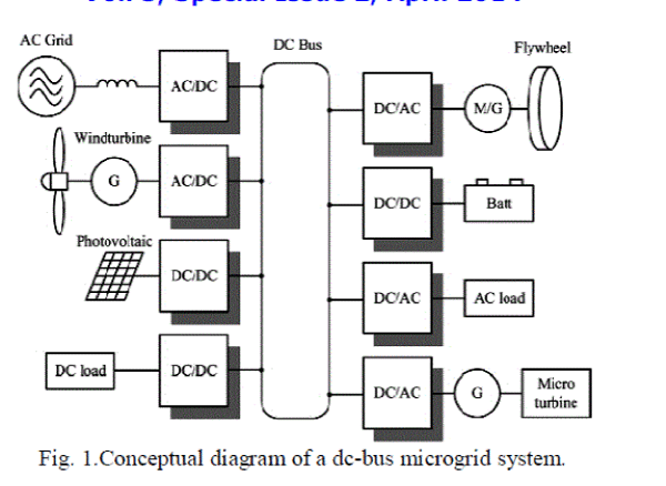
stability, still persist. DC ring bus-based systems can become a feasible solution because microgrids are small, localized
systems where the transmission loss is negligible. A conceptual diagram of the dc-bus microgrid is shown in Fig.
1.While the advantages of dc microgrids are considerable, the protection of dc distribution systems has posed many
challenges, such as autonomously locating a fault within a microgrid, breaking a dc arc, dc protective equipment, and
certainly the lack of standards, guidelines, and experience [3]. This paper presents a fault detection, isolation and
identification of fault location scheme for a low-voltage dc ring bus microgrid system. |
| The main objectives of the proposed scheme are to detect the fault in a bus segment between devices and then to isolate
the faulted section so that the system continues to operate without disabling the entire system. Also proposed is a noniterative,
deterministic fault location technique using a probe power unit. The information on fault location is extracted
from the probe current. |
 |
| The probe power unit can also be used for a pilot test to determine whether the fault is temporary before main CB
reclosing to avoid system damage that can be expected when the fault is permanent. To accomplish these goals, this
paper proposes a ring-type dc bus-based microgrid system which has a segment controller between connected
components. |
LOW-VOLTAGE DC-BUS MICROGRID |
| Compared to high- voltage dc (HVDC) systems, the low-voltage dc (LVDC) system is a relatively new concept in
electric power distribution. For small scale systems, LVDC microgrids have many advantages over traditional ac
distribution systems. For both ac and dc microgrids, power-electronic converters are required to connect a variety of
sources and loads to a common bus. Using a dc bus requires fewer stages of conversion [3]. Furthermore, the cables for
the ac and dc power systems are chosen based upon the peak voltage of the system, and the power delivered by an AC
system is based on the rms values, while the dc power is based on the constant peak voltage. Hence, the dc system can
deliver √2 times that of an AC system with the same cable. And dc systems do not suffer from the skin effect.
Therefore, the dc system can utilize the entire cable, thus decreasing losses [4]. |
| Problems arise with dc microgrids when a system needs re-liable and versatile protection. AC systems have plenty of
experience and standards when it comes to system protection. DC systems do not have either of these advantages. The
switchgear in dc systems must be very robust in order to handle the dc arc that is created during the interruption of fault
currents. The protection devices commercially available for low-voltage dc-bus systems are fuses and circuit breakers
(CBs) [3]. Traditional ac CB mechanisms, which rely on the natural zero crossing of the ac current to open the circuit,
are inadequate to interrupt dc currents. More important, the fault persists because the operating time of the CB
increases. Allowing a fault current to persist on a microgrid bus could be catastrophic. |
| Because the microgrid systems need to be multi terminal, voltage source converters (VSCs) must be used to interface
different subsystems to bus. When a fault occurs on the dc side of a VSC system interfacing the ac source, the insulatedgate
bipolar transistors (IGBTs) lose control and the freewheeling diodes become a bridge rectifier feeding the fault. The
challenge of protecting VSC systems is that the fault current must be detected and extinguished very quickly as the
converter’s fault withstand rating is generally only twice the full-load rating [5]. |
FAULTS IN DC DISTRIBUTION SYSTEMS |
A. Possible Faults |
| Two types of faults exist in dc systems: 1) line to line and 2) line to ground, which can be seen in Fig. 2. A line-to-line |
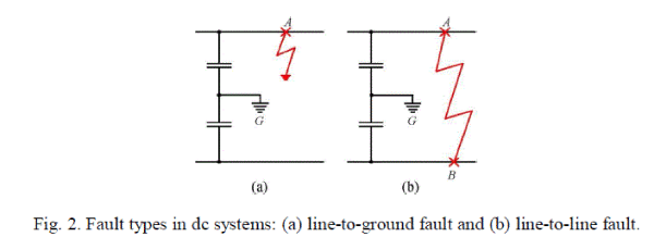 |
| fault occurs when a path between the positive and negative line is created, short circuiting them together. A line-to -
ground fault occurs when either the positive or negative pole is short circuited to ground. The line-to -ground faults are
the most common types of faults in industrial distribution systems [6]. VSCs may experience internal switch faults that
can cause a line-to-line short circuit fault. This is a terminal fault for the device that cannot be cleared; in most cases,
the device needs to be replaced. Hence, dc fuses would be a proper protection measure for this kind of fault. In AC
systems, the AC-side CB will trip. |
B. DC Fault Currents |
| When a fault occurs in a segment, the line current will split between load current and fault current |
 |
| The magnitude of the fault current depends on the fault location and resistance of the fault current path. If the
impedance of fault path is low (e.g., a line-to-ground fault with solid ground), the current polarity at the receiving end
could be reversed, preventing the load from being supported at all. The fault current from the power source and bus
capacitors can be given as follows: |
 |
| where Vs is the line voltage, Rc and Lc are the equivalent resistance and inductance including source, line and ground
component, and Rc and Ce are the equivalent series resistance (ESR) and capacitance of bus capacitors, respectively.
The time constant of the dc fault current is quite small because the line resistance of the dc system is negligible
compared to ac power systems that have high reactance in the line. The bus voltage will drop or even collapse,
depending on the capacity of the power supply and energy-storage device in the bus, and the grounding impedance. |
C. Fault Protection Techniques |
| Protection of dc systems has been done with dc protective switchgear as well as conventional ac devices, such as CBs
and fuses. Although ac devices have advantages, such as low cost, maturity of technology, and shorter lead time, dc
devices are a better option whenever possible. DC protective devices can interrupt constant current faster than their ac
counterparts to isolate faulted lines and maintain the operation of unfaulted lines [2]. |
D. Fault-Location Techniques |
| Several methods have been investigated for locating faults in ac systems. Fault location can be determined using the
computed reactance based on recorded fault current and voltage information at one terminal of a line [13]. Fundamental
phasor information [14], phasor measurement unit (PMU) [15], and fault voltage sag [16] can be used as well. The traveling wave method computes the difference in time of arrival for a transient wavefront at two or more locations
connected to a fault to locate the fault [17]. |
| The existing dc fault-location techniques use rate of current rise, magnitude of current, current oscillation pattern [12],
continuous wavelet transform [30], distributed parameter line model [19], iterative estimation using reference voltages
[20], and artificial neural networks [18]. The accuracy of the aforementioned methods shows promise; however, the |
 |
| dependence on two-terminal measurements restricts the practical uses. The instrumental aspects, such as the impact of
sensor error and communication delay, have been investigated in [21]. Further-more, because the dc fault current rises
so quickly, it may have to be interrupted before some useful information for the fault location can be obtained. Also, it
may be difficult to extract the necessary information for fault location at the time of the fault, because the fault current
is determined by other bus segments and components as well as fault impedance. |
PROPOSED FAULT PROTECTION METHOD |
| Unlike other previously presented methods for dc systems [12], [22], the proposed protection method does not require a
complete shutdown of the microgrid. Rather, only the affected section is isolated and de-energized. This is
demonstrated with a ring-bus configuration for the dc bus, creating several zones of protection that can be defined using
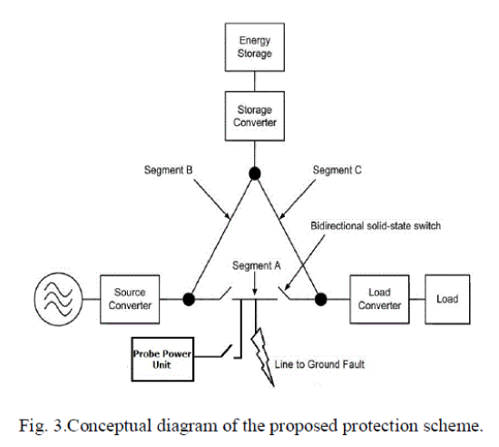
overlapping nodes and links within the bus. Each node consists of three CBs, and two CBs at each end of a bus segment
form a link. This can be implemented for the positive and negative pole in bipolar systems. At each node, a probe
power unit will be installed to locate the fault and test the bus for reclosing. A detailed diagram for the proposed system
is shown in Fig. 3.The proposed protection scheme consists of the following components. |
A. Fault Detection and Isolation |
| The master controller monitors the difference of two current readings of slave controllers in a segment |
 |
| where i in and i out is the line current at each end of the bus segment. When the difference exceeds the threshold, the
controller sends the appropriate commands to slave controllers so that the faulted segment can be separated from the
system. Because the proposed system uses the differential relaying principle monitoring only the relative difference of input and output current of a segment, it can detect the fault on the bus regardless of fault current amplitude or power
supply’s feeding capacity. Once the faulted segment has been isolated, the bus voltage will be restored and remainder
of the system can continue to operate on the ring-type bus. Even with multiple faulted segments, the system can operate
partially if the segments from some power sources to loads are intact. The possibility of the fault around the device
connection point can be minimized if the segment controllers are installed as close to the connection point as possible. |
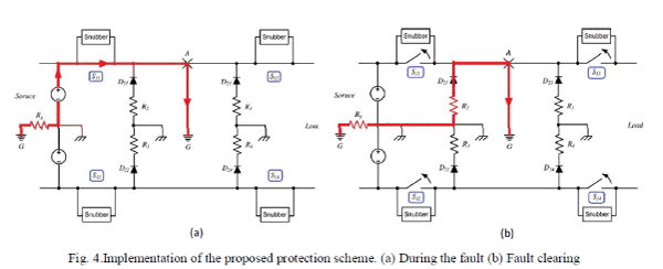 |
| The implementation of the proposed protection scheme is shown in Fig. 4, which shows the configuration of segment A
in Fig. 3. Semiconductor based bidirectional switches S1 and D2 diodes are used for segment separation and fault
current freewheeling, respectively. In normal operations, switches S1 are closed and diodes D2 are open. When a fault
occurs, the master controller detects it using the current information from the slave controllers and opens S1 switches.
Diodes D2 are conducting at the same time to form a freewheeling path for fault currents so that the S1 switches can
open and the fault current can be extinguished through resistors. The segment controllers can detect the fault current of
the line-to-ground fault (from point A or B to G) and line-to-line fault (from point A to B). A turnoff snubber circuit is
included for S1 switches to limit the voltage overshoot due to the line inductance. |
| The line-to-ground fault is shown in Fig. 4. It can be seen that the fault current is isolated and extinguished in the
freewheeling loop. The freewheeling path impedance determines the extinction rate of the fault current, which can be
given as follows: |
 |
| where Rf and Lf represent the resistance and inductance in the freewheeling path, respectively. |
| When a line-to-ground or a line-to-line fault occurs in the distribution line, the bus voltage collapse would not allow the
load to ride through if the current is limited from the source because of insufficient capacity. This is especially true for
the VSC-interfaced microgrid systems. Furthermore, the fault current needs to be extinguished as quickly as possible
even if the system has sufficient current feeding capacity. Therefore, one of the best solutions would be to isolate the
faulted line as soon as possible and continue operation with intact bus segments and subsystems. To achieve this, the
segment controller needs to be capable of fast differential current detection and bus switch control. An automatic
reclosing algorithm would be necessary for fault recovery and more robust operation [7]. |
B. Snubber Circuit |
| Snubber circuits are indispensable to protect the solid-state CBs from the voltage transient due to the inductance of the
bus cable. It is more so especially in a loop-type bus where the line inductance exists on both sides of the CB unlike the point-to-point-type system. Although the fault current needs to be interrupted as quickly as possible, the high di/dt
could make the transient voltage catastrophically high for the solid-state switches. There are a couple of snubber circuit
topologies to suppress the overvoltage at turn-off due to line inductance, such as decoupling capacitor, discharge
restricted decoupling capacitor, discharge-charge-type RCD snubber, and discharge-suppressing-type RCD snubber [8].
It has been reported that the decoupling capacitor has low losses but also oscillation issues and RCD snubbers have
higher losses but no oscillation problem and good for higher current applications [9]. Since the solid-state CBs do not
switch in high frequency, charge-discharge-type RCD snubber has been chosen for better voltage suppression
performance. |
C. Fault Segment Modelling With the Probe Power Unit |
| Once the faulted bus segment is isolated, a second-order RLC circuit can be formed with the probe power unit through
the fault path as shown in the equivalent circuit shown in Fig. 8. When the switch Sp in the probe power unit is closed,
the dynamics of the probe current can be expressed as |
 |
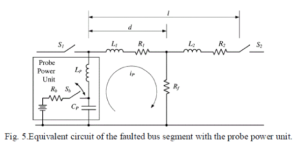 |
| The equivalent resistance and inductance of the fault path will be given as the sum of line and fault resistances and the
line and probe inductance, respectively as shown in Fig. 5. The line leakage capacitance can be neglected because the
capacitance of the probe capacitor is significantly larger. The probe capacitor and probe inductance will determine the
frequency of the probe current. Because of the large R/L ratio of power cable [23], the probe current will decay too
fast without probe inductance. Hence, the fault circuit components, including the probing unit components, are given as |
 |
 |
 |
| where R1 and L1 are the line resistance and inductance to fault location, which are defined as |
 |
 |
 |
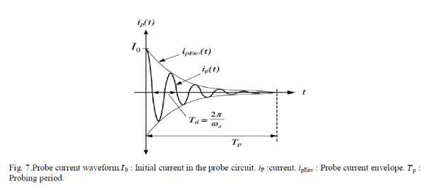
| Since there is no driving voltage in the circuit except the initial probe capacitor voltage, the probe current i can be
given as a zero-input response of the RLC circuit |
 |
 |
 |
 |
 |
 |
 |
D. Identification of Fault Location |
| The underdamped response frequency of the probe current is a function of natural frequency and damping factor. If the
damping factor is small enough (controllable with the probe capacitor and inductor), the damped response frequency
becomes very close to the natural frequency, which is function of inductance of the faulted segment L1, probe inductance LP, and probe capacitance CP.Because the capacitance and inductance of the probe circuit (CP and LP) and
unit inductance of the line Lu are known parameters, the distance to the fault location can be readily calculated from the
probe current frequency fip using (17) |
 |
 |
 |
 |
 |
| The damped resonance frequency ������can be obtained from sampled current data using a fast Fourier transform (FFT)
algorithm. |
SIMULATION RESULT |
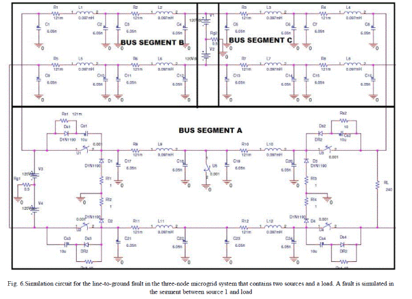
| A computer simulation has been performed for a microgrid system that consists of three typical energy devices: a
source, a load, and energy storage. They are connected as shown in Fig. 7. Stiff dc power sources are assumed so that a
constant fault current is fed by the sources without a voltage drop. A 240V bipolar dc bus with 200m bus segments and
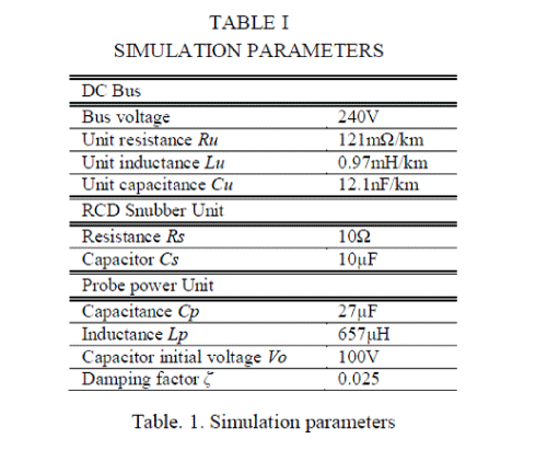
a fault at the middle (100m) of the bus is simulated. Simulation parameters can be found in Table I. |
 |
 |
 |
| A positive line-to-ground fault in the middle of the bus segment A is simulated at 1ms. Fig. 8 shows the source and
load-side current of a line-to-ground fault with and without protection. It can be seen that the current from source
increased to 180 A after 0.5 msec. The fault current magnitude depends on the impedance of the fault path. The
currents at each end of the segment which had been identical before faultshow clear difference after fault. Line-to- line
fault current will be higher be-cause there is no resistance to limit it. Therefore, fast detection and isolation are
critical.It has been assumed in the simulation that the segment controllers can detect it and open/close solid-state CBs in
250 s. considering the speed of current microcontrollers and switching devices, fast interruption in this speed range
isfeasible. Fig. 8.And Fig. 9.also shows that the fault currents are extinguished when the faulted segment is separated. |
 |
| Fig. 10 shows the voltage transient across the solid-state CB S11 without and with the snubber circuits, respectively. It
also shows the fault extinction in the freewheeling path. The voltage transient at turnoff due to the line inductance and
high di/dt can be very high and it can easily damage the solid-state switch. It can also be seen that the voltage transient
is suppressed by a snubber circuit at a tolerable level. |
| Fig. 11 shows the voltage across the load. The ground fault pulls the positive pole voltage to zero, and the bipolar dc
bus will experience a voltage offset on the faulted pole. However, the load voltage is quickly restored after the faulted
segment has been separated. |
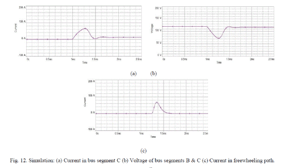
| Fig. 12 shows the current in the bus segment C and voltage of bus segment B and C and current in freewheeling path.
The bus segment C experience the ground fault current and voltage sag is experience in bus segment B and C. |
| After the faulted segment is separated by IEDs, it is tested by the probe power unit to confirm the fault status and
location. The capacitance and inductance value of the probe power unit components can be computed using 27 F
and657 μH, respectively, with 0.025 damping factor and 50-ms probing period. The probe current decays as designed
and clearly shows the oscillation frequency . For the fault at 100m on the bus segment, the frequency is 718.95 Hz.
The FFT analysis extracts the frequency as 719.0 Hz and the fault location was identified using (17) with 0.02% error
(100.02m). |
 |
| The protective devices in bus segments B and C have been omitted in this simulation because the proposed
protectivescheme that detects the difference in net current flow will not be triggered if there is no fault in the bus. This
can be verified by the currents flowing into and out of the intact bus segment C shown in Fig. 12. Even with the
transient caused by the fault on the bus segment A, the incoming and outgoing currents of segment C are identical. The
proposed scheme that detects the current difference is robust to common-mode noise and transient due to a fault. |
CONCLUSION |
| A fault detection, isolation, and location scheme for the dc microgrid system has been presented in this paper. The
proposed protection scheme consists of IEDs which are capable of detecting fault current in the bus segment and
isolating the segment to avoid the entire system shutdown. A ring bus based microgrid system with IEDs, has been
used. For the separated faulted segment, a fault-location algorithm using a probe power unit without having to reclose
the main CBs has also been presented. This bus probing method can ensure the proper line status before reclosing and,
hence, improves the system reliability and mean time between failure (MTBF) of protective gear. Furthermore, it can
be readily applied to ac power systems to eliminate the issues caused by reclosing failure, as well as to identify the fault
location. Successful performance of fault detection, isolation, and location have been shown using computer
simulations. |
References |
- R. Dugan and T. McDermott, âÃâ¬ÃÅDistributed generation,âÃâ¬Ã IEEE Ind.Appl. Mag., vol. 8, no. 2, pp. 19âÃâ¬Ãâ25, Mar./Apr. 2002.
- H. Nikkhajoei and R. Lasseter, âÃâ¬ÃÅDistributed generation interface to the CERTS microgrid,âÃâ¬Ã IEEE Trans. Power Del., vol. 24, no. 3, pp. 1598âÃâ¬Ãâ1608, Jul. 2009.
- D. Salomonsson, and L. Soder, âÃâ¬ÃÅProtection of low-voltage DCmicro-grids,âÃâ¬Ã IEEE Trans. Power Del., vol. 24, no. 3, pp. 1045, Jul. 2009.
- M. Saeedifard, M. Graovac, R. Dias, and R. Iravani, âÃâ¬ÃÅDC power sys-tems: Challenges and opportunities,âÃâ¬Ã in Proc. IEEE Power Energy Soc.Gen. Meeting, July 2010, pp. 1âÃâ¬Ãâ7.
- J. Candelaria and J.-D. Park, âÃâ¬ÃÅVSC-HVDC system protection: A re-view of current methods,âÃâ¬Ã in Proc. IEEE/Power Energy Soc. PowerSyst. Conf. Expo., Mar. 2011, pp. 1âÃâ¬Ãâ7.
- Jae-Do Park and Jared Candelaria, âÃâ¬ÃÅFault Detection and Isolation in Low-VoltageDC-Bus Microgrid SystemâÃâ¬Ã IEEE Trans.Power Del.,vol. 28, no. 2, Apr. 2013
- Jae-Do Park, Jared Candelaria, Liuyan Ma, and Kyle Dunn, âÃâ¬ÃÅDC Ring-Bus Microgrid Fault Protection and Identification of Fault LocationâÃâ¬Ã IEEE Trans. Power Del., vol. 28, no. 4, Oct 2013
- J. Das and R. Osman, âÃâ¬ÃÅGrounding of AC and DC low-voltage and medium-voltage drive systems,âÃâ¬Ã IEEE Trans. Ind. Appl., vol. 34, no. 1, pp. 205âÃâ¬Ãâ216, Jan./Feb. 1998.
- J. Machowski, J. Bialek, and J. Bumby, Power System Dynamics: Sta-bility and Control. Hoboken, NJ: Wiley, 2011.
- N. Mohan, T. Undeland, and W. Robbins, Power Electronics Con-verters, Applications, Design, 3rd ed. Hoboken, NJ: Wiley, 2003.
- Y. Zhang, S. Sobhani, and R. Chokhawala, Snubber considerations for IGBT applications, 2002.[Online]. Available: www.irf.com/technical-info/designtp/tpap-5.pdf
- L. Tang and B. Ooi, âÃâ¬ÃÅProtection of VSC-multi-terminal HVDC against DC faults,âÃâ¬Ã in Proc. IEEE 33rd Annu. Power Electron. Specialist Conf., Nov. 2002, vol. 2, pp. 719âÃâ¬Ãâ724.
- T. Takagi, Y. Yamakoshi, M. Yamaura, R. Kondow, and T. Mat-sushima, Development of a new type fault locator using the one- terminalvoltage and current data,âÃâ¬Ã IEEE Trans. Power App. Syst., vol. PAS-101, no. 8, pp. 2892, Aug. 1982.
- C. Apostolopoulos and G. Korres, âÃâ¬ÃÅA novel algorithm for locating faults on transposed/untransposed transmission lines without uti-lizing line parameters,âÃâ¬Ã IEEE Trans. Power Del., vol. 25, no. 4, pp. 2328âÃâ¬Ãâ2338, Oct. 2010.
- Y.-H. Lin, C.-W.Liu, and C.-S. Chen, âÃâ¬ÃÅA new PMU-based fault de-tection/location technique for transmission lines with consideration of arcing fault discriminationâÃâ¬ÃâPart II: Performance evaluation,âÃâ¬Ã IEEETrans. Power Del., vol. 19, no. 4, pp. 1594âÃâ¬Ãâ1601, Oct. 2004.
- R. Pereira, L. da Silva, M. Kezunovic, and J. Mantovani, âÃâ¬ÃÅImproved fault location on distribution feeders based on matching during-fault voltage sags,âÃâ¬Ã IEEE Trans. Power Del., vol. 24, no. 2, pp. 852âÃâ¬Ãâ862, Apr. 2009.
- X. Lin, F. Zhao, G. Wu, Z. Li, and H. Weng, âÃâ¬ÃÅUniversal wavefront positioning correction method on traveling-wave-based fault-location algorithms,âÃâ¬Ã IEEE Trans. Power Del., vol. 27, no. 3, pp. 1601âÃâ¬Ãâ1610, Jul. 2012.
- C. Chang, S. Kumar, B. Liu, and A. Khambadkone, âÃâ¬ÃÅReal-time detec-tion using wavelet transform and neural network of short-circuit faults within a train in DC transit systems,âÃâ¬Ã Proc. Inst. Elect. Eng., Elect.Power Appl., vol. 148, no. 3, 2001.
- J. Suonan, S. Gao, G. Song, Z. Jiao, and X. Kang, âÃâ¬ÃÅA novel faultloca-tion method for HVDC transmission lines,âÃâ¬Ã IEEE Trans. Power Del., vol. 25, no. 2, pp. 1203âÃâ¬Ãâ1209, Apr. 2010.
- J. Yang, J. Fletcher, and J. OâÃâ¬Ãâ¢Reilly, âÃâ¬ÃÅShort-circuit and ground fault analyses and location in VSC-based DC network cables,âÃâ¬Ã IEEE Trans.Ind. Electron., vol. 59, no. 10, pp. 3827âÃâ¬Ãâ3837, Oct. 2012.
- H. Li, W. Li, M. Luo, A. Monti, and F. Ponci, âÃâ¬ÃÅDesign of smart MVDC power grid protection,âÃâ¬Ã IEEE Trans. Instrum. Meas., vol. 60, no. 9, pp. 3035âÃâ¬Ãâ3046, Sep. 2011.
- L. Tang and B. Ooi, âÃâ¬ÃÅLocating and isolating DC faults in multi-terminal DC systems,âÃâ¬Ã IEEE Trans. Power Del., vol. 22, no. 3, pp. 1877âÃâ¬Ãâ 1884, Jul. 2007.
- A. Bergen and V. Vittal, Power Systems Analysis, 2nd ed. Upper Saddle River, NJ: Prentice-Hall, 2000.
|