Induction motors are used in many industrial applications in a wide range of operating areas as they have simple and robust structure, and low production costs. Induction motors are now being used more as compared to before due to their certain advantages such as versatility, dependability and economy, good self-starting capability, offers users simple, rugged construction easy maintenance, low cost and reliability. The reliability of an induction motor is of great Importance in industrial as well as commercial, aerospace and military applications. Also the knowledge about fault mode behavior of an induction motor drive system is extremely important from the standpoint of improved system design, protection, and fault tolerant control.[1] In this paper different problems are dealt, such as overvoltage, over current , over temperature, over speed, inrush current, vibration monitoring which are being faced by IM’s during it’s course of operation. There are various methods for fault detection and protection of IM. Some of them are On-line fault detection, Stator fault monitoring techniques, Microcontrollers based protection system and Programmable Logic Controller (PLC) based protection system. In this study, the method used is PLC based protection system of IM.
Keywords |
| PLC, PIC, Fault diagnosis, Reliability |
INTRODUCTION |
| Although Induction machines are reliable, they are subjected to some undesirable stresses, causing some faults
resulting in failures. Safety implies the introduction of redundant element which should detect the failure and lead to
the adequate solution. Due to the recent development in the Programmable Logic Controller(PLC) technology, it is
widely used in most industrial applications and utility plant . One possible application is to use the PLC for fault
diagnosis of IM. Researchers have studied a variety of machine faults and have come to conclusion that machine
failures include mechanical and insulation faults.There are various other types of insulation system faults and
mechanical faults. |
(A) INSULATION SYSTEM FAILURE |
| Insulation system failure plays an important role in electrical machine failure. The major insulation failures are caused
by moisture and over temperature. |
(B) MECHANICAL FAILURE |
| The major faults in this category can be broadly classified as |
| (1) Stator faults. |
| (2) Broken rotor bars |
| (3) Static and/or dynamic air gap irregularities |
| (4) Misalignment |
| (5) Bearing and gear box failures. |
| The possible detection methods to identify the motor faults are listed as follows |
| (a) Vibration monitoring |
| (b) Electromagnetic field monitoring using search coils |
| (c) Chemical analysis |
| (d) Temperature measurement |
| (e) Speed measurement |
| (f) Voltage measurement |
| (g) Current measurement |
| (h) Radio frequency emission monitoring |
| (i) Acoustic noise measurement |
| (j) Partial discharge method. |
| Nowadays, the most widely used area of programmable logic controller (PLC) is the control circuits of industrial
automation systems. The PLC systems are equipped with special I/O units appropriate for direct usage in
industrial automation systems[2]. The input components, such as the pressure, the level, and the temperature sensors,
can be directly connected to the input.The driver components of the control circuit such as contactors and solenoid
valves can directly be connected to the output.Many factories use PLC in automation processes to diminish production
cost and to increase quality and reliability [2]. |
 |
| This paper explains a PLC-based protection and monitoring method for a single-phase induction motor.
The new solutions for various faults of the current, voltage, the speed, and the winding temperatures of an IM
occurring in operation have been achieved with the help of a PLC. This paper is organized as given next.SectionII
introduces the PLCs.SectionIII presents real-time implementation details of hardware,software,and measurement of
the system. Section IV expresses the experimental studies of motor fault detection and protection. The research is
finally concluded in Section V. |
PROGRAMMABLE LOGIC CONTROLLER |
| A PLC or a programmable controller is a small computer used for automation of real-world processes, such as control
of machinery on factory assembly lines. A PLC can be programmed to sense, activate, and control industrial
equipment.Therefore ,a PLC incorporates a number of I/O points, which allow electrical signals to be interfaced.
Input and output components of the processes are connected to the PLC; and the control program is loaded on the PLC
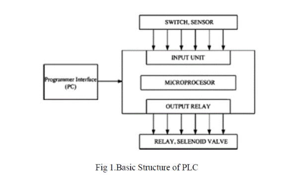
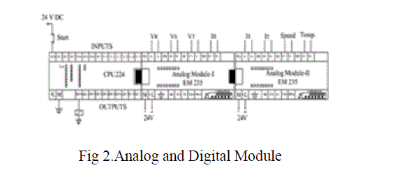
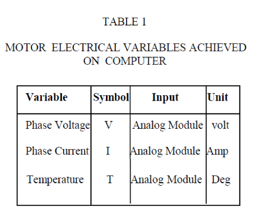
memory. The basic structure of the PLC is illustrated in Fig. 1. In this study, the PLC measures the current, the voltage,
the temperature, and the speed of an induction motor through analog inputs. In addition, it continuously monitors the inputs and activates the outputs according to the program.An analog module is primarily required for processing analog
signals. Analog modules usually work in accordance with 8 or 12 bit systems. One or more than one analog sensors can
be connected to the analog module in accordance with their types. In Fig. 2, connection scheme containing circuit
elements of a PLC is illustrated. |
 |
 |
CONTROL SYSTEM OF IM |
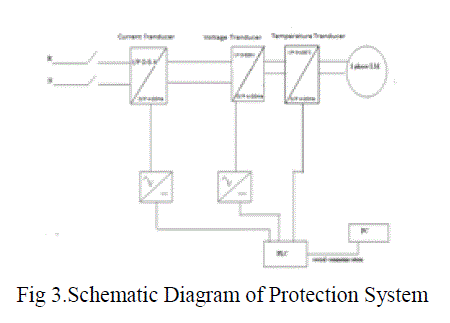
| A block diagram for the protection of IM is shown in fig.3. It consists of the measuring instruments for the
measurement of the voltage, the current, the winding temperature and the rotor speed. The proposed protection system
can better be understood under the following three categories as the hardware, the instrumentation and the software.
The tasks of these categories are explained in the following sections. |
 |
 |
A. Hardware |
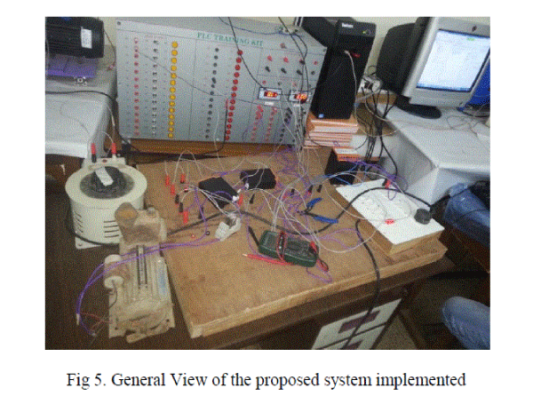
| The protection system used in this study consists of a 0.25 HP single phase IM,having specifications as 230V
voltage,current is 1.4A,1600 rpm,an auto transformer ,three transducers as current transducer, voltage transducer and
temperature transducer to make the specifications compatible with PLC, a Siemens CPU , and PLC(Slider Company).
A photograph of the proposed system is demonstrated in Fig. 5. |
B. Instrumentation |
| The currents and the voltages of the induction motor in the protection system were measured including current
transformers and voltage transformers .Since voltage, current and time are real time parameters, analog module of PLC
is used. But the PLC cannot accept such high values of voltage current and temperature.So the three transformers are
used to step down the values of voltage, current and temperature as 0-10V voltage and 4-20 mA current.Converted
current and voltage values were then transferred to the PLC analog module. The temperature signal was also magnified
and transferred to PLC analog module.Now by using the software in PC the values are checked and if the conditions
are true PLC’s one output is connected to a relay which is normally in NC condition,it energizes the coil in relay and
the IM is ON.If anytime the conditions are false the relay will come in NO condition and the motor stops |
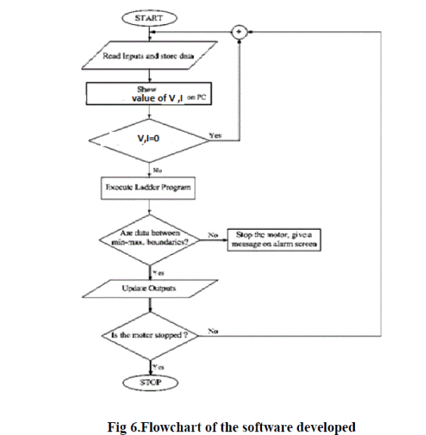
C. Developed Software |
| In order to achieve the protection of the IM easily, a PLC program was developed.The PLC system provides a design
environment in the form of software tools running on a host computer terminal that allows LADs to be developed,
verified, tested, and diagnosed. First, the high-level program is written in LADs. The LAD is then converted to binary
instruction codes, so that they can be stored in RAM or erasable programmable read-only memory (EPROM). Each
successive instruction is decoded and executed by the CPU. The function of the CPU is to control the operation of
memory and I/O components and to process data according to the program. Each input and output connection point on
a PLC has an address used to identify the I/O bit. Flowchart of the program is given in Fig.6. |
 |
 |
SIMULATION AND RESULTS |
| The computer interface program has been written and the software used for PLC is SOMACHINE. The communication
is achieved according to ―Modbus‖ protocol between the PLC and a computer. All operation instructions come from
the programmable logic controller to either switch ON/OFF any component of the subsystem depending on its state or
the state of another component.[3] |
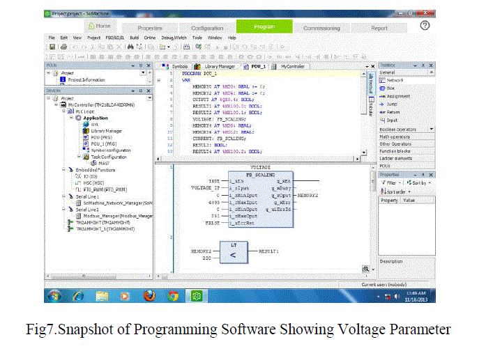 |
| The snapshot of the programming software(SOMACHINE) describing voltage parameter is shown in Fig 7. Similarly
the current and temperature parameters can also be described in a similar manner. |
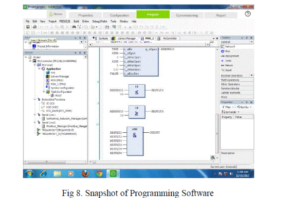 |
| Result can be compared with the fixed maximum and minimum values of voltage, current and temperature as shown in
Fig 8.If all the values are within the prescribed limit the output of the AND gate will be true.The most prominent faults
in case of induction motors,has been detected and diagnosed using PLC.[4]If the induction motor is required to be run,
minimum and maximum values of the voltage, the current, the temperature, and the speed have to be entered from the
keyboard first. After entering all values, the motor is then ready for starting. |
CONCLUSION |
| A 0.25 HP,1.4A current,230V,1600 rpm single-phase IM has been connected to the protection system through the
measuring components. The proposed PLC-controlled protective relay deals with the most important types of these failures, which are summarized as the phase lost, the over/undercurrent, the over/under voltage, the unbalance of supply
voltages, the overload, the unbalance of phase currents, the ground fault, and the excessive repeated starting. If any
fault is observed during online operation of the motor, a warning message appears on computer and then the motor is
stopped. The most common causes of motor troubles which account for the majority of problems are highlighted[5].
The test has been found successful in detecting the faults and in recovering them.The voltage,current,winding
temperature are then directly being displayed on the computer screen with the help of the software developed. After
having all these data they are controlled considering their tolerance values. The system continues to run under normal
condition but in case any kind of fault occurs on the system i.e. if the value of phase voltage, phase current, rotor speed
or winding temperature increases beyond it’s defined value then the PLC will immediately gives signal to the control
circuit of the motor and thus the motor stops. |
| The results showed that a reliable PLC-based protection system including all variables of IM and operators have been
developed. The use of PLC has greatly reduced the cost of implementing new control circuits on the plant floor and has
reduced the time needed to make various changes to the relay circuit as demanded by a given process. |
References |
- M. Benbouzid, M. Vieira, and C. Theys, ―Induction motor’s fault detection and localization using stator current advanced signal processing techniques,‖ IEEE Trans. Power Electron., vol. 14, no. 1, pp. 14–22, Jan. 1999.
- M. G. Ioannides, ―Design and implementation of PLC-based monitoring control system for induction motor,‖IEEE Trans. Energy Convers.,vol. 19, no. 3, pp. 469–476, Sep. 2004.
- Okoli F.I, Onubogu J.O, Okezie C.C, Okorogu V.N, ‖The Simulation of the Control of an Industrial Mixer using PLC’’ International Journal of Inventive Engineering and Sciences (IJIES) ISSN: 2319–9598, Volume-1, Issue-2, January 2013,25.
- ArfatSiddique, Member, IEEE, G. S. Yadava, and Bhim Singh, Senior Member, IEEE IEEE TRANSACTIONS ON ENERGY CONVERSION, VOL. 20, NO. 1, MARCH 2005
- William R. Finley, Senior Member, IEEE, and Robert R.Burke, Senior Member, IEEE,”Troubleshooting Motor Problems,IEEE TRANSACTIONS ON INDUSTRY APPLICATIONS, VOL. 30, NO. 5, SEPTEMBER OCTOBER 1994.
- I. Colak, H. Celik, ˙I. Sefa, and S. Demirbas, ―On line protection system for induction motors,‖Energy Convers. Manage., vol. 46, no. 17, pp. 2773– 2786, 2005.
- F. Filippetti, G. Franceschini, C. Tassoni, and P. Vas, ―AI techniques in induction machines diagnosis including the speed ripple effect,‖IEEE Trans. Ind. Appl., vol. 34, no. 1, pp. 98–108, Jan./Feb. 1998.
- Thomson, D. Rankin, andD.G.Dorrell, ―On-line current monitoring to diagnose airgap eccentricity in large three-phase induction motors-Industrial case histories verify the predictions,‖IEEE Trans. Energy Convers., vol. 14, no. 4, pp. 1372–1378, Dec. 1999.
- W. T. Thomson and M. Fenger, ―Current signature analysis to detect induction motor faults,‖IEEE Ind. Appl. Mag., vol. 7, no. 4, pp. 26–34, Jul./Aug. 2001
|