The permanent magnet brushless DC motor found more popularity in industrial, residential and aerospace applications because of their inherent advantages over conventional brushed DC motor. To impact rotation to this motor electronics are nece=ssary. The paper mainly concentrated on multiphase machines and developed the ten step commutation logic for five phase BLDC motor. The four quadrant operation and fault tolerant capability of five phase BLDC was evaluated with ten step commutation logic and the results are presented. The simulation of presented commutation logic was carried out in MATLAB/SIMULINK and the results are validated with the experimental results. The hardware implementation of ten step commutation was done in an AT89C51 microcontroller platform and the results are presented.
Keywords |
| commutation, multiphase, ten step commutation, microcontroller |
INTRODUCTION |
| The multiphase PMBLDC motor found more importance in medium and high power drives because of their inherent
advantages of high reliability, fault tolerant capability, reduced current per phase, reduced amplitude and increased
frequency of torque pulsation over the convention three phase BLDC motor [1]-[7]. These motors find wide
application in variable speed drives because of the advancement in solid state devices and the availability of rare earth
alloy permanent magnet [8],[9]. As the name indicates the multiphase system is a system with numerous numbers of
windings or circuits. The winding arrangement and the construction of multiphase motor are similar to that of a three
phase motor except the number of windings arranged in the stator[10]. The number of stator winding is equal to the
number of phases and these windings can be arranged either in star or in delta fasion. [1],[7]-[10].To impact rotation to
a BLDC motor its winding have to be energized in a proper sequence and the order of energization will depends on the
position of rotor. The hall sensors are used to achieve the position information and these sensors are arranged in a stator
winding [11], [12]. For the proper operation of BLDC motor, a suitable commutation sequence and a power electronic
converter is necessary. For BLDC motors, the type of commutation scheme adopted determines the torque ripple at the
output which attributes to one of the major losses [13]. There are two types of conventional commutation schemes,
such as trapezoidal commutation and sinusoidal commutation. |
| In BLDC motors the phase windings are arranged in trapezoidal fashion in order to generate the trapezoidal BEMF
waveform and in sinusoidal or distributed winding arrangement to get a sinusoidal back EMF. Based on the back EMF
pattern, two types of commutation techniques such as trapezoidal commutation and sinusoidal commutation are
developed. In sinusoidal commutation, all the phases are conducting at any instant of time. The current through each
phase is smooth and continuous which reduces the torque ripple [11]-[13]. The implementation of Sinusoidal
commutation is complex because of the requirement of highly precise encoders for getting the position information. |
| Trapezoidal commutation or six step commutation is one of the simplest commutation schemes which can implement
with the information achieved from the hall sensors [11]. In this commutation scheme only two phases is energized at a
time and the remaining one phase will be in a non-energized condition. The switching sequence was developed with the
concept, that the hall sensor pattern and back EMF waveform are aligned each other. |
| This paper extents the concept of six step commutation in three phase BLDC motor to ten step commutation in five
phase BLDC motor [10]. The proposed commutation sequence for five phase BLDC motor was developed with the
same concept of six step commutation logic [14]- [19]. The simulation results are presented by using
MATLAB/Simulink as the simulation tool and its results are validated with the experimental results. To evaluate the
fault tolerant capability of five phase BLDC motor, the experiment was conducted when the motor operates in four
phase and three phase by releasing the phases in running condition and examined the performance of motor. The
hardware implementation of ten step commutation was carried out in an AT89C51 microcontroller platform and the
experimental results are also presented. |
COMMUTATION SCHEME |
| The conventional DC motor commutes itself with the use of a mechanical commutator whereas brushless DC motor
needs electronic commutation for the direction control of current through the windings. Different types of commutation
schemes are available to impact rotation to a BLDC motor. Among them the most common is trapezoidal commutation
and sinusoidal commutation. |
| Sinusoidally commutated brushless controllers attempt to drive the three phase motor windings with three currents that
vary smoothly and sinusoidally. This eliminates torque ripple and commutation spikes associated with trapezoidal
commutation [13]. This control method provides better performance and efficiency at lower speed. The main drawback
associated with this method is the requirement of highly precise encoders for position sensing. The trapezoidal
commutation logic is one of the simplest methods to drive a three phase BLDC motor. It is also called as six step
commutation, since it requires six steps to complete one electrical cycle [12].This method utilizes hall sensors for
position information. The switching sequences corresponding to the Hall sensor pattern are developed from the concept
that the back EMF waveform and hall pattern are aligned each other. In this method two phases are conducting at every
instant of time and the remaining one phase will be in non-energized condition. This method is very popular because of
the simplicity of its control algorithm and with reduced switching loss. |
| The six step commutation logic in a three phase system can be utilized in a five phase system as ten step commutation
logic. The proposed commutation is one of the simplest forms of commutation logic which enables the four quadrant
operation of the motor. The switching sequence of presented topology was developed with the concept that the hall
devices are aligned properly with the generated back EMF voltage [10]. Here each stator windings are displaced by 72
electrical degrees and at every 36 degree two windings get energized with positive power, two with negative power and
the remaining one will be in the non-energized condition. The sequence of energization of stator winding will depends
on the rotor position. The position information can achieved from the hall sensors mounted in stator winding. The hall
sensors provide a logical high or low signal depending upon the rotor North Pole or South Pole passes [14]. Ten
possible combinations of hall sensor patterns are available for a five phase BLDC motor. The proposed commutation
logic requires ten step to complete one electrical cycle and have the name ten step commutation. The number of
electrical cycles require to complete one mechanical rotation will depend on the number of rotor pole pairs. |
 |
 |
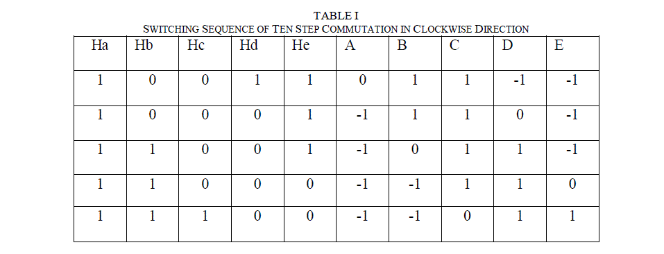
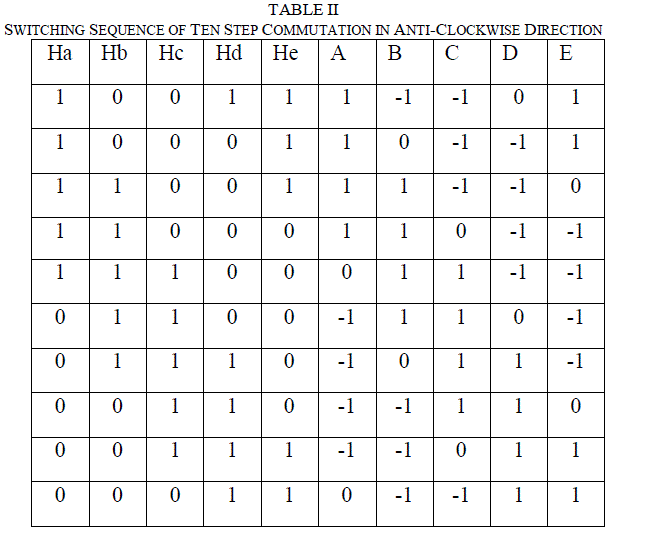
| The switching sequence required for operating the motor in clockwise and counter clockwise direction are different.
Table I indicates the hall sensor pattern and the corresponding switching sequence developed for operating the motor in
anti-clockwise direction and Table II indicates the switching sequence in clockwise direction. In table I corresponding
to the hall position 10011, the phase B and C are conducting with positive current and phase D and E with negative
current, and the phase A in a non –energized condition, where as in table II corresponding to the same hall position A
and E are energized with positive power, phase B and C with negative power. The proposed commutation scheme
provides a quasi-square shaped current waveform with its value coming to zero twice in an electrical cycle. This
commutation scheme offers simplicity in implementation with reduced switching loss and also offers the operation of
motor in both direction with same speed. |
 |
SIMULATION RESULTS |
| The mathematical model of five phase BLDC motor drive was developed in MATLAB/SIMULINK [4]-[6], [10]and
the simulation of proposed ten step commutation scheme was carried out. The simulation parameters used are
L=0.7mH and R=0.7 ohm.The duration of conduction of each switch was controlled by a PWM signal of 10 KHz
frequency, generated by comparing the command signal with triangular waveform of frequency 10 KHz. The hall
sensor pattern and the corresponding switching sequence developed for a five BLDC motor was entered using
embedded MATLAB functions. The current through each phase winding was modelled using the equation (1). |
 |
| where i = A, B, C, D and E |
| The instantaneous back EMF in BLDC motor is given in equation (2) where,ω is the rotor mechanical speed and θ is
the rotor electrical position. |
 |
| The torque developed by the motor is given in the equation (3) |
 |
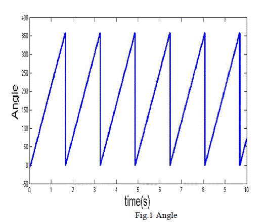
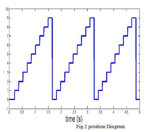
| Fig. 1 represents the angle of rotation of BLDC motor.The angle obtained is compared with 360 degree and whenever
the angle is greater than 360 degree the integrator is reset to the initial value. From the angle of rotation we get the
positions and the Fig.2 represents the position of rotor. If rotor moves from 0 to 360 degree, the position is 1 and for the
next 36 degree movement the position is 2 and similarly for other angles. The back EMF waveform of presented
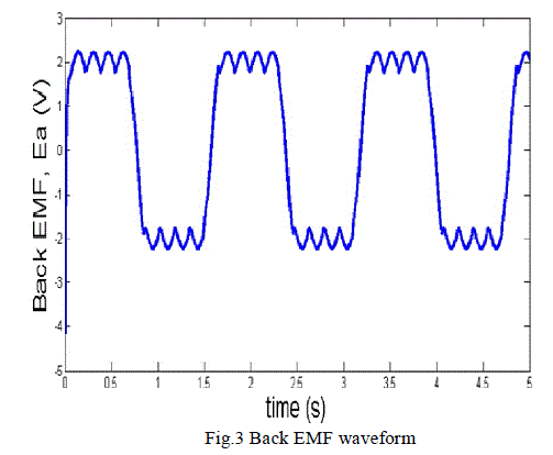
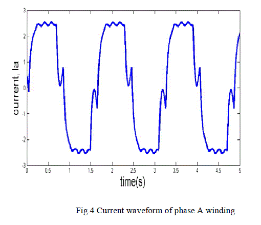
topology has a trapezoidal shape as shown in Fig.3 and the current through phase A winding of motor is given in Fig 4.
Here the current waveform has a quasi-square shape with its value comes to zero twice in an electric cycle. |
 |
 |
 |
 |
EXPERIMENTAL RESULTS |
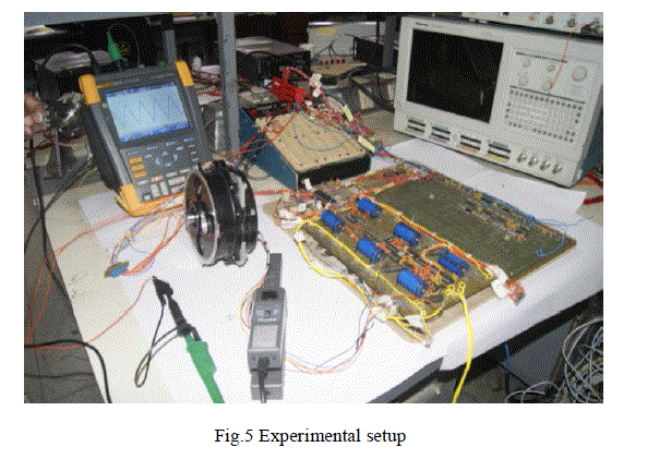
| The experimental setup of five phase BLDC motor drive with ten step commutation logic was developed as shown in
fig.5. It includes a PWM and dead band generator, a precision source to provide the command signals, and a five phase
BLDC motor connected to five legged inverter. The experiment was carried out in a five phase, 28V, 600 rpm BLDC
motor and the PWM pulses for the MOSFET switches in the five legged inverter driven byIR2110 driver circuit are
generated by the microcontroller.The proposed commutation sequence corresponding to the hall sensor pattern and the
PWM and dead band signals are implemented in an AT89C51 microcontroller platform. It is a 40 pin IC, which can be
reused for many times. A PWMsignal of 10KHz frequency and a dead band signals of 4 microseconds are developed
using analogue setup. The experiment was carried out at different conditions five phase, four phase and three phase to
check the reliability and fault tolerant capability of motor with the presented ten step commutation logic. |
 |
 |
 |
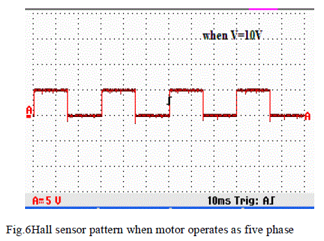
| The speed of rotation of motor is evaluated with the halls sensor pattern.Fig.6 shows the hall sensor pattern of five
phase BLDC motor when motor operates at 10V. The current through phase A winding of five phase BLDC motor
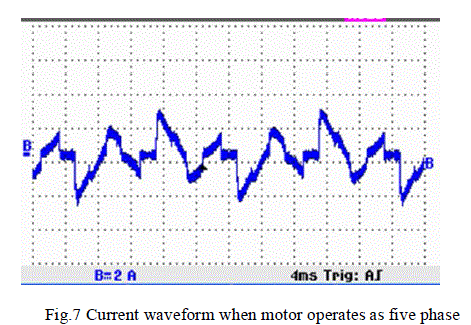
when operates with ten step commutation is as shown in fig.7. Here the current waveform has a quasi-square shape
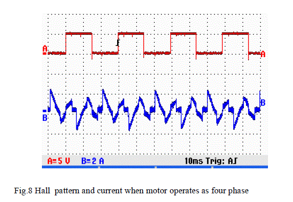
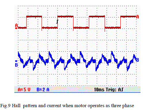
with its value comes to zero twice in an electrical cycle [12] as predicted by the simulation. Fig 8 and fig.9 shows the
hall sensor pattern and the current of Phase A winding, when motor operates at four phase and three phase. From the
wave form its cleared that the speed of operation of motor remains unchanged even though it’s one or two phases get
failed during its operation. |
 |
 |
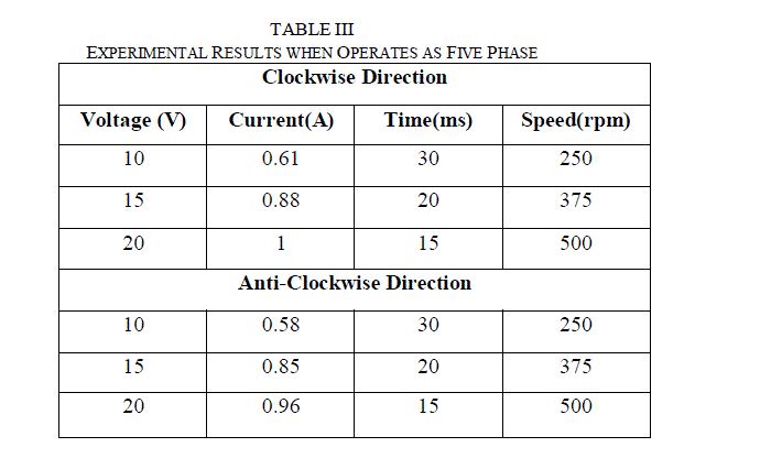
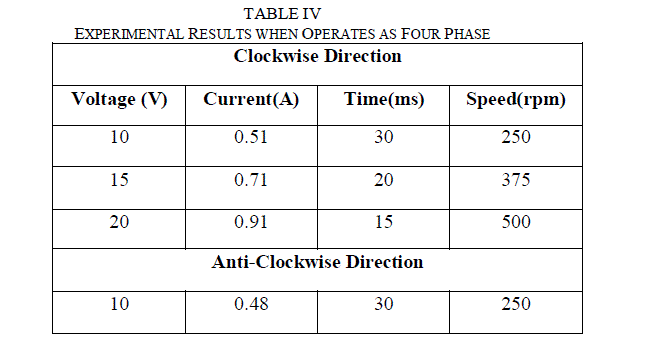
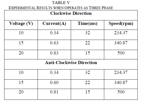
| The reliability and the fault tolerant capability of motor with ten step commutation was analysed by operating the
motor at different conditions five phase, four phase and three phase and at different voltages 10V,15V and 20V. The
performance of motor at different conditions is examined and the results are tabulated in tableIII, table IV and tableV.
The speed of rotation of motor in clockwise and anti-clockwise direction with ten step commutation was evaluated by
changing the command signal and it is observed that the presented commutation scheme can operate the motor with
same speed in both direction and established the four quadrant operation of motor with proposed commutation scheme. |
 |
 |
 |
CONCLUSION |
| The proposed ten step commutation logic for five phase BLDC motor was developed and established the four quadrant
operation of motor.The simulation of proposed commutation algorithm was carried out in MATLAB/SIMULINK and
the results are validated with the experimental results. The algorithm provides simple implementation with reduced
switching loss. The hall sensor pattern and the corresponding switching sequence at which the rotor rotates are
determined and the corresponding waveform ofcurrent through each phase is verified with its simulation result and
experimental result.The speed of rotation of motor and its current waveform when motor operates in five phase,four
phase and three phase was evaluated and the results of the same with different voltages are presented and thereby the
reliability and fault tolerant capability of five phase BLDC motor with ten step commutation logic was validated. |
References |
- G.K singh "multiphase induction machine drive research- a survey" Electric power system research ,2002
- Padmarajayedamale "Brushles DC (BLDC) motor fundamentals" AN885,microchip technology,2003
- Nilson N. Franceschetti,M. Godoy Simoes "A New Approach for Analysis, Modeling and Simulation of Brushless Multiphase Machines"IECONO1 : The 27th Annual Conference of the IEEE Industrial Electronics Society,2001
- Pragasenpillay and Ramu Krishnan "Modeling, Simulation, and Analysis of Permanent-Magnet Motor Drives,Part 11: The Brushless DC Motor Drive"IEEE Transactions on Industry application vol.25,March/April, 1989
- HemchandImmaneni,"Mathematical ModellingAnd Position Control Of Brushless Dc (BLDC) Motor" International Journal of Engineering Research and Applications, Vol.3, Issue 3, pp.1050-1057, May-Jun 2013.
- K.shivanarayana, G.Anil,K.srividyaSavitri" Simulation of Four Quadrant operation and speed Control Of BLDC Motor on MATLAB/Simulink" International Journal of Science and Modern Engineering Vol.1, ,July 2013
- G.H Jang and C.I. Lee " Dual winding Method of a BLDC motor for Large Starting Torque and High Speed"IEEE Transactions on magnetics, vol.41, October 2005
- ShuaiLuand Keith Corzine " Multilevel multiphase propulsion drives "IEEE Electric Ship TechnologiesSymposium,2005
- DevisreeSasi, JishaKuruvilla P, AnishGopinathâÃâ¬ÃÅGeneralized SVPWM Algorithm for Two Legged Three Phase Multilevel InverterâÃâ¬Ã International Journal of Power Electronics and Drive System (IJPEDS), Vol.3, pp279-286, September 2013,
- Cicily Antony, AnishGopinath and Beena M Varghese âÃâ¬ÃÅ Poly phase BLDC motor drive with Ten step commutationâÃâ¬Ã International Conference on Magnetics, Machines & Drives (AICERA-2014 ICMMD), July 2014.
- AnishGopinath and M R Baiju," space vector PWM for Multilevel inverters- A fractal Approach "Power Electronics and drive system, PEDS , 2007
- Sreejithkumar N, WaheedaBeevi M, AnishGopinath " Quasi Sinusoidal commutation for BLDC motor- A simplied Approach on 16 Bit Microcontroller Platform . International Conference on Power Electronics, Drives and Energy System, December 2012.
- AnishGopinath, K M Chandran, Jaya B, M.N Namboothiripad and John P. Zachariah âÃâ¬ÃÅMotor Drives for High Power Electromechanical Actuation Systems for Space Applications âÃâ¬ÃâChallenges and ProspectsâÃâ¬ÃÂ
- M. Godoy Simes and P. Vieira " A Five-Phase Brushless DC-Machine Direct Drive System "EPE Journal,Vol. 14 , August 2004
- Tony Mathew1 and Caroline Ann Sam " Modelling and Closed Loop Control of BLDC Motor Using a Single Current Sensor" International Journal of Advanced Research in Electrical, Electronics and Instrumentation Engineering Vol. 2, June 2013
- Heinz Willi Vander Broeck,HanschristophSkudelny and Georg Viktor Stanke " Analysis and Realization of a Pulsewidth Modulator Based on Voltage - Space Vectors "IEEE Transactions on Industry ApplicationsâÃâ¬Ã VOL 24. NO I . Jan/Feb 1988
- Xiaoyan Huang, Andrew Goodman, Chris Gerada, Youtong Fang and Qinfen Lu "Design of a Five-Phase Brushless DC Motor for a Safety Critical Aerospace Application "IEEE Transactions on Industrial ElectronicsâÃâ¬Ã VOL. 59, NO. 9, SEPTEMBER 2012
- PragasanPillay and R. Krishnan, "`Modeling of Permanent Magnet Motor Drives "IEEE Transactions on Industrial Electronics VOL. 35, NO 4, NOVEMBER 1988
- Anas S R, HemanthJaison, AnishGopinath, M.N Namboothiripad and M.P Nandakumar "Modeling and Simulation Analysis of a Redundant Electromechanical Actuator based Position Servo System" International Conference on Computer, Communication and Electrical Technology
|