Keywords
|
| Permanent Magnet Synchronous Machine, Space-vector pulse width modulation (SVPWM), Electric Vehicles (EVs) |
INTRODUCTION
|
| Automotive engine emissions unit of measurement recognized as a major offer of of targeted pollution, notably in urban areas. although the inside combustion engine remains the dominant prime mover for technological and price reasons, moreover the growing dependence on fossil fuel, together with a heightened concern over the environmental impact of private transportation, has led worldwide the country's governments analysis and sponsor research into different vehicle to avoid wasting the consumed energy. One amongst these future technologies is that the hybrid electrical vehicle (HEV), usually that includes each associate interior combustion engine and an electrical motor, with the goal of manufacturing lower emissions whereas getting superior fuel economy. |
| Power converters area unit progressively employed in automotive applications for several reasons, like power acquisition, power management, and consumption reduction. The design and management techniques of the control system have matured to a particular degree. However, several forms of sudden inverter faults occur therefore thus in trade fields. |
| The main advantage of asymmetrical multilevel inverters is that the optimisation of levels with a minimum range of power supplies. However, this optimized multilevel system still needs an oversized range of isolated and floating dc supplies, that makes these converters sophisticated to implement in electrical vehicles (EVs), as a result of the system would force several independent battery packs. |
| The objective of this paper is to develop a brand new dc-link topology for associate asymmetrical multilevel electrical converter, supported an easy high-frequency link (HFL), that permits exploitation just one power provide (battery pack, fuel cell, or others). This single dc- supply system is especially appropriate for EVs however may also be used for HEVs and industrial machine drives. The system has associate inherent regulation of the voltages provided among the H-bridges; so, the complete range of levels are often made at any amplitude of voltage, relying solely on the only dcsupply regulation, which may be controlled with a chopper. |
| The changes in electrical and thermal indicators area unit discovered regularly by a observation system. At the top of the check (reaching injury criterion or failure), totally different analyses are performed (acoustic scanning and SEM imaging), and therefore the injury is listed consistently. |
| The (VSI) contain semiconductor devices, that area unit rugged however suffer from failure like short circuit (SC) or open circuit (OC) due excess electrical and thermal stresses that area unit experimental in several applications[1][2]. This failure will categorised as several form of faults. Therefore, the information and knowledge regarding the faults behaviors area unit important to system design, protection and fault tolerant control. The inverter faults could influence the operation of the entire system. Also, so as to stop the harmful influence moreover on enhance the reliableness of the system, the fault detection and diagnosing area unit need. During this work MOSFET inverter is employed. The mentioned faults could cause the drive system shut-dawn looking on the state of the system. However, the system also can keep operative below the fault since it does not continually lead to the incapability of system operation. |
| Several failures will afflict electrical-motor drives, and lots of completely different remedial techniques are projected[3]. Therefore, far, redundant, or conservative design has been employed in industrial applications, wherever continuity of operations could be a key feature. This can be particularly vital in high impact automotive applications, like electrical vehicles (EVs) and hybrid EVs (HEVs), wherever the drive system should feature, among others, high reliableness and strength for various vehicle-operating conditions. As a result of even limp-back operation is most popular over no operation, the remedial techniques could result in short-torque transients and even to permanently reduced drive performance after fault, on the condition that the drive still goes running. |
FOUR-LEG INVERTER DRIVE
|
| The drive composed of a 3 phase star-connected permanent-magnet synchronous machine (PMSM) and a four-leg electrical converter with the fourth leg connected to the neutral point of the machine winding has the flexibility to deal with most electrical faults, a minimum of if only 1 electrical converter leg or one machine part becomes unavailable[4]. To carry on the drive with associate open part, this references need to be modified to stay an acceptable rotating mechanical device field [10] [11]. Management reconfiguration is then the operation that consists in control the management references once the fault has been detected and known. This reconfiguration depends on the sort of control accustomed drive the machine[5] [6]. |
| The drive model composed of a three-phase star-connected PMSM and a four-leg inverter is shown in Fig 1. It needs fault isolation contactors[4]. |
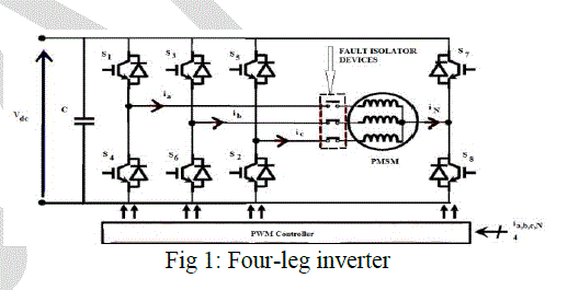 |
| The fourth cell Q4 with switches S7 and S8 plays a standby role once one or 2 of the cells Q1 (S1 or S4), Q2 (S3 or S6), Q3 (S2 or S5) to be connected to the phases of the PMSM fails. The fourth cell Q4 is inactive throughout normal operation of the voltage inverter, in alternative words its switches S7 and S8 are uncontrolled if there's no failure and are in turn-off state. The fourth cell Q4 is in waiting mode. Once a reconfiguration is formed when a failure has been detected, the defective cell is isolated and therefore the fourth standby cell Q4 is then place into active mode, its switches S7 and S8 controlled therefore on be created or else turn-on and turn-off throughout acceptable times. Once a observation and management device has detected and diagnosed a failure within the cell related to it, for instance Q1, it forces its switches S1, S4 to the turn-off state and it forces the associated electrical uninflected device to the turn-off state. |
| If a winding fault occurs in the PMSM, the faulted phase is isolated by keeping open the corresponding two power switches. The supplementary inverter leg will continue to drive the currents, assuring practically the normal current through the remained healthy phases. Since the additional inverter leg is connected to the neutral point of the PMSM, the neutral current caries the phase currents of the remaining phases: |
| i0 = ia + ib + ic |
 |
| It is clear that for a correct operation of the converter additional fault detection module has to be added, as well also a phase isolation logic which will command the power switches during faulty operation [7] [8]. |
| This design needs the utilization of fault isolation contactors, this will increase the price. This is often a disadvantage in electrical vehicle applications concerning reliableness. The proposed resolution is given in next section. |
3-H BRIDGE INVERTER ARCHITECTURE
|
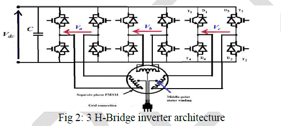
| The proposed power structure consists of three H-bridges, each of them supplying a separate PM synchronous machine (PMSM) motor phase. This architecture does not require the fault isolation contactors. This uses a machine without neutral point. This allows full dc link voltage to the each stator winding of PMSM. |
 |
| More commonly, basic modifications are proposed that involve additional connections to the machine windings (e.g. a wye-connection brought out) and an additional switch or switches in the controller. Radical approaches involve independent inverters (multiphase, H Bridge) for each phase [5] and complete redesign of the machine itself to provide isolation of both electrical and magnetic circuits. |
DRIVE MOTOR CONTROL MODELLING
|
| A nonsalient pole PMSM is used in proposed system and for the motor damping effect is not considered. By using the generalized Concordia transformation, the diagonalisation of stator inductance matrix, |
 |
| The zero sequence current of the proposed motor drive architecture is not to be null. The (1) gives two fictitious machines (main machine and zero sequence fictitious machine) related to zero line and α- β frame. The three phase machine is modeled by using Resistance R and Phase inductance (equal to the leakage inductance) L. The main machine produces torque and is given by |
 |
| The purpose of the motor drive is to produce desired torque with reduced losses for that the h-bridge converter inverter power switches are controlled by using SVPWM Control method and is explained in the next section. |
SPACE VECTOR PULSE WIDTH MODULATION(SVPWM)
|
| Space vector modulation is a PWM control method for multi-phase AC generation, in which the reference signal is sampled regularly; after each sample, non-zero active switching vectors adjacent to the reference vector and one or more of the zero switching vectors are selected for the appropriate fraction of the sampling period in order to synthesize the reference signal as the average of the used vectors. |
 |
| The reference voltage vector, VREF is the vector summation of all 3 modulating voltages and can be represented in the following equation: |
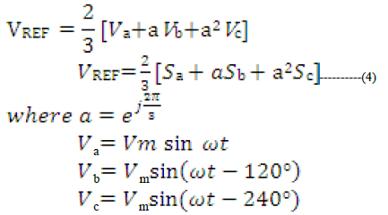 |
| Sa, Sb, Sc are the switching states representing each phase. |
| The three stator windings of the PMSM are connected separately to each H-Bridge. For each H-bridge four descrete states present and produce 3 levels of voltage +Vdc 0,-Vdc. For complete converter it provide 27 switching states. The stator voltages are given as in Table-I. |
| Table-I Stator Voltages |
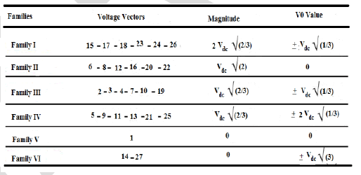 |
| For controlling both machines the PWM controller needs a space vector [V0 * Vα * V β *]T. The 3H-bridge inverter can only provide an average value of this voltage set point, using a PWM technique. Therefore, four different discrete voltage vectors {V 1, V 2, V 3, V 4}among the 27 inverter possibilities are necessary for solving this SVPWM problem. |
 |
| To minimize switching losses, it is crucial to construct a sequence guaranteeing an equitable distribution of the number of switches per leg to obtain a limited number of switches and to avoid excessive switching while sector changing. Taking the first sector as an example, Fig. 4 shows the turn-on and turn-off numbers. |
 |
| The three H-bridges are represented by three rectangles. Points inside them depict the number of switches achieved from the beginning of the half period: Red points depict current switches, whereas black points symbolize previous switches. For instance, a single H-bridge needs two switches, i.e., one turn-on switch and one turn-off switch, to switch from the normalized voltage +1 to −1 or −1 to +1. |
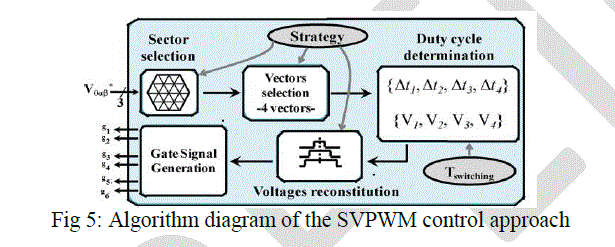 |
| Fig. 12 shows that an SVPWM implementation diagram allowing the determination of the gate signals of the power switches. At a switching period Tsw, the algorithm locates the reference voltage V0αβ ∗in the α−β frame and defines the current sector and, hence, the four correct vectors. next, it finds each duty cycle. Then, it defines the related switching sequence. And lastly the gate signals are generated with a small sampling time. |
SIMULATION RESULTS
|
| The simulation blocks and results are given below for a three phase inverter by associating a fourth additional bridge to neutral point of PMSM and 3-H bridge inverter drive feeding PMSM in both normal and degraded operating modes. |
| Parameters for Simulation analysis are: |
| INPUT DC VOLTAGE= 500V |
| SWITCHING FREQUENCY= 1KHZ |
| LOAD RESISTANCE= 10ohm. |
| LOAD INDUCTANCE= 10Mh |
| A) FOUR LEG INVERTER IN NORMAL OPERATING MODE: |
 |
| The simulation model of 4-leg inverter is shown in Fig.6. The scope gives the current in three phase windings of PMSM during normal condition. |
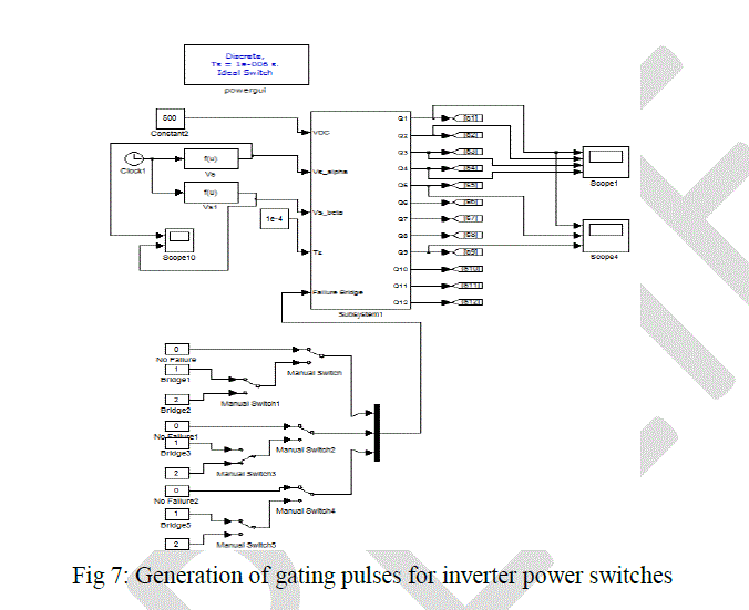
| The inverter is designed by using MOSFET devices. The switching signals for the inverter gates are generated by SVPWM control method. Fig.7 shows the generation of gating pulses for inverter power switches and also shows the failure mechanism with the help of manual switches. |
 |
| INPUT (DC Supply Voltage=500V): |
 |
| The input DC supply is shown in Fig 8. |
| OUTPUT: |
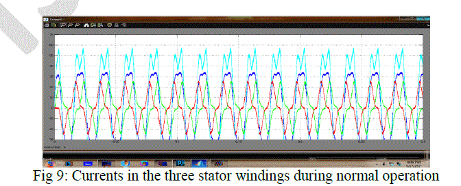 |
| The Fig 9 shows the currents in three stator windings during normal operation. |
 |
| During degrading mode the motor supplies with two phases and this allows the flow of neutral current as in fig 10. |
| B) PROPOSED 3 H-BRIDGE INVERER DRIVE |
| Discussing about normal operation and fault-tolerance a fundamental danger of the full H-bridge topology is presented. In normal conditions the top and bottom stages of a half of the H-bridge of a single branch are never on at the same time, unless a malfunctioning command is received from its control system. This can be avoided by monitoring the work of the control system. |
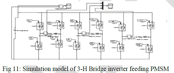 |
| The simulation model of 3-H bridge inverter feeding PMSM is shown in fig 11. Here each H-bridge is used to supply the each of three stator windings of PMSM individually. |
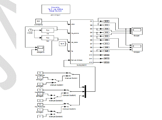 |
| The gating pulses for inverter power switches are generated as in Fig 12. |
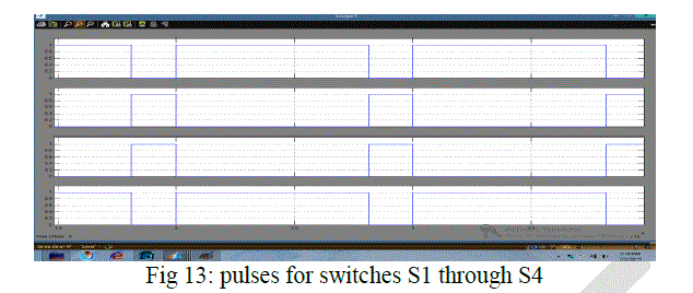 |
| The gating pulses are generated as in fig 13 by using fig 12. Fig 13 shows the pulses for S1 through S4 switches. |
 |
| A direct short circuit can occur if the top and bottom switches of the same branch are turned on at the same time. The fault is created by changing the positions of themanual switch in Fig 12. During switch failure the affected H-Bridge can only produce two descrete levels (0 and +Vdc) instead of three. Therefore, the inverter can produce 18 space vectors. Then the output currents obtained as follows: |
 |
| Another problem, a short circuited power switch is more difficult to solve. The solution is the total isolation of the entire branch opening, and keeping permanently opened all the corresponding power switches. This way the fault tolerance is ensured by the physical separation of the damaged branch. Of course in this case the motor has to be fault-tolerant to be able to continue its work (even at lower torque and at higher torque ripples). |
CONCLUSION
|
| This work gives successful effortsfor implementation of SVPWM control method to the H-bridge power converter feeding three-phase permanent magnet Synchronous motor in Electric Vehicle. The main advantages of this include: with the equal distribution of the switchings among the inverter switches the losses are reduced, balancing of switching rate between the three H-bridges, insensitivity to duty cycle, the drive performance is maximized, and current ripples are reduced. This presented method has been implemented by using Matlab/Simulink environment. |
| The proposed system with 3 H-Bridges supplying three phases of the PMSM individually have the ability to operate in both normal and degraded modes. |
References
|
- K. R. Chowdhury, M. Di Felice, “Search: a routing protocol for mobile cognitive radio ad hoc networks,” Computer Communication Journal, vol. 32, no. 18, pp. 1983-1997, Dec.20
- K. M. Passino, “Biomimicry of bacterial foraging for distributed optimization,” IEEE Control Systems Magazine, vol. 22, no. 3, pp. 52-67, 2002.
- Q. Wang, H. Zheng, “Route and spectrum selection in dynamic spectrum networks,” in Proc. IEEE CCNC 2006, pp. 625-629, Feb. 2006.
- R. Chen et al., “Toward Secure Distributed Spectrum Sensing in Cognitive Radio Networks,” IEEE Commun. Mag., vol. 46,pp. 50–55, Apr. 2008.
- H. Khalife, N. Malouch, S. Fdida, “Multihop cognitive radio networks: to route or not to route,” IEEE Network, vol. 23, no. 4, pp. 20-25, 2009.
- Y.-C. Liang et al., “Sensing-Throughput Trade-off for Cognitive Radio Networks, ”IEEE Trans. Wireless Commun., vol. 7, pp. 1326–37 ,April 2008.
- P. K. Visscher, “How Self-Organization Evolves,” Nature, vol. 421, pp. 799–800 Feb.2003.
|