This project presents the comprehensive performance analysis on the principle of operation, design considerations and control algorithms of the field oriented control (FOC) for a permanent magnet synchronous motor (PMSM) drive system and proportional-integral-derivative PID for speed control in closed loop operation. To perform speed control of typical PMSM drives, PID controllers and FOC method are classically used. The Space Vector Pulse Width Modulation is a standard model that provides pulse to the inverter. The orientation of pulse from FOC to PMSM is subjected to monitoring and control, made feasible by PID controllers. It is popularized that control properties of PID controller is far superior in consideration with PI controller. In this paper, the FOC system is enabled with PID replacing PI from standard model. The system was experimented on MATLAB/SIMULINK 2010a and the results with proposed structure outperformed the standard model.
Keywords |
| FOC, PMSM, MATLAB, Simulink, PID and for Speed Control. |
INTRODUCTION |
| Permanent Magnet Synchronous Machine is the brushless motor designed for low voltage electronic
equipment. In their initial stage the operations of PMSM were limited to simple DC motor circuits with low power
input and high performance index. However, with later improvement in machines introduced the applications of PMSM
in heavy industrial equipment considering the benefits over conventional motors. The panorama of PMSM has covered
areas of automobiles, military, precision tools, Medical instruments etc. However PMSM motors perform poorly with
open-loop scalar V/Hz control, since there is no rotor coil to provide mechanical damping in transient conditions. |
| Field Oriented Control is the most popular control technique used with PMSMs. FOC technique operates
smoothly and provides maximum torque, full speed range and instantaneous acceleration and deceleration by
controlling the iq and dq currents for three phase voltage supply in lower performance applications. To convert the low
voltage input in high voltage for motor coordination, the FOC is implemented with a voltage inverter. The capability of
inverter to modulate the voltage signifies the operating range of PMSM. The difference in the input voltage pulse and
the required modulation voltage are subject of PID controllers installed in FOC controllers. However, to generate
maximum torque at zero speed and maximize the overall performance of PMSM the inverters are generally operated in
over modulation range. The difference in actual flux and torque compared with estimated values are basis for switching
of inverters. The gate (electric) pulses for control of inverter are derived from a standard unit known as Space Vector
Pulse Width Modulation. |
LITARATURE REVIEW |
| PM motor drives have been an area of interest for the past thirty years. Different researchers have carried out
modeling, analysis and simulation of PMSM drives. This content offers a brief review of some of the published work
on the PMSM drive system. |
| In the year 1986 Jahns, T.M., Kliman, G.B. and Neumann, T.W. [1] proposed that in IPMSM had special
features for adjustable speed operation. The control principle of the sinusoidal currents in magnitude along with phase
angle wrt the rotor direction was a path for achieving smooth response of torque control. |
| Extr-high energy magnets are used in IPM motor to improve the performance characteristics of the rotor. In
this method Sebastian, T. Slemon, G. R. and Rahman, M. A. [2] in 1986, presented equivalent electric circuit models
for these motors and compared estimated parameters with measured parameters. |
| Pillay and Krishnan, R. [3] in 1988, presented views on PM motor drives and classified them into two types.
These are permanent magnet synchronous motor drives and brushless dc motor (BDCM) drives. The PMSM had a
sinusoidal back emf and required sinusoidal stator currents which produced constant torque while the BDCM had a
trapezoidal back emf, required rectangular stator currents for producing constant torque. |
BASIC PRINCIPLES OF FOC AND TRANSFORMATION |
| Vector Control of currents & voltages which result in control of the space alignments of the electromagnetic fields. |
| a) Rotor flux oriented control |
| b) Stator flux oriented control |
| To perform vector control |
| 1. Measure the motor phase currents |
| 2. Transform them into the two phase system (a, b) using Clarke transformation. |
| 3. Calculate the rotor position angle |
| 4. Transform stator currents into the d,q-coordinate system using Park transformation |
| 5. The stator current torque (isq) and flux (isd) producing components are controlled separately by the controllers |
| 6. The output stator voltage space vector is transformed back from the d,q-coordinate system into the two phase system
fixed with the stator by inverse Park transformation. |
| 7. Using the space vector modulation, the output three-phase voltage is generated. |
| Clarke's Transformation: |
| The Clarke transformation changes a three phase system into at two phase system with orthogonal axes in the same
stationary reference frame. The new two phase variables are denoted α and β the original and transformed system. The
ABC parameters are transformed into αβ0 parameters by equation |
 |
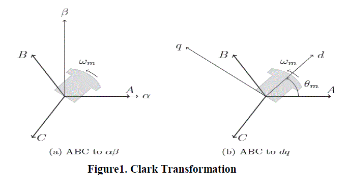 |
| Park's Transformation: The Park transformation changes a three phase system in one stationary reference frame into
a two phase system with orthogonal axes in a different rotating reference frame. The two new phase variables are
denoted d and q, and are referred to as the motors direct- and quadrature axis. The ABC parameters are transformed
into dq0 parameters and in reverse by equation |
 |
| By using the Park's transform, the stator parameters such as voltages, currents, and flux linkages, are associated with
fictitious stator windings that rotate with the rotor. The time varying parameters between stator and rotor are thus
eliminated and all variables are expressed in the same orthogonal or mutually decoupled direct- and quadrature axes. |
| Inverse Park transformation: Equation of inverse park transformation |
 |
| Space vector pulse width modulation : |
| The space vector pulse width modulation (SVPWM) technique of the most popular technique due to a higher DC bus
voltage and offered easy digital realization. The concept of SVPWM relies on the representation of the output voltage
the inverter output as space vector or space phasors. Space vector representation of the output voltages of the inverter is
realized of the implementation of SVPWM. The maximum output voltage based on the space vector theory is 2/ √3 1.55 times as large as the conventional sinusoidal modulation. It enables to feed the motor with a higher voltage than
the easier sub-oscillation modulation method. This modulator allows to have a higher torque at high speeds, and a
higher efficiency. The space vector is defined as |
 |
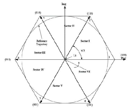 |
| Space vector 1, 2…6 called the active states and 7, 8 called zero states vectors. Are redundant vector but they are used
to minimize the switching frequency. The inverter is operating in the six-step mode. |
IMPLEMENTATION OF CONTROLLED METHOD FOR PMSM |
| The P stands for proportional control, I for integral control and D for derivative control. This is also called a
three term controller. The basic function of a controller is to execute an algorithm based on the control engineer's input (tuning constants), the operator’s desired operating value (set point) and the current plant process value. In most cases,
the requirement is for the controller to act so that the process value is as close to the set point as possible. In a basic
process control loop, the control engineer utilizes the PID algorithms to achieve this. |
| With its three-term functionality covering treatment to both transient and steady-state responses, proportionalintegral-
derivative(PID) control offers the simplest and most efficient solution to many real-world control problems.
The PID controllers are usually standard building blocks for industrial automation. The most basic PID controller has
the form: |
 |
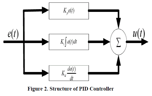 |
| A control method which is popular because of its robustness, its simplicity, and its reusability is PID control. A PID
controller contains a proportional gain, an integrator, and a differentiator (hence its name), all of which are summed
together to produce the output of the controller. The transfer function of a PID controller has the form |
 |
| Field oriented control of PMSM : |
| Field oriented control of PMSM is one important variation of vector control methods. The aim of the FOC method is to
control the magnetic field and torque by controlling the d and q components of the stator currents or relatively fluxes.
With the information of the stator currents and the rotor angle a FOC technique can control the motor torque and the
flux in a very effective way. The main advantages of this technique are the fast response and the little torque ripple. The
implementation of this technique will be carried out using two current regulators, one for the direct-axis component and
another for the quadrature-axis component, and one speed regulator. |
 |
| As shown in the figure, there are three PID regulators in the control system. One is for the mechanical system (speed)
and two are for the electrical system (d and q currents). |
| At first, the reference speed, ωref, is compared with the measured speed, ωr, and the error signal, εω, is fed to
the speed PID controller. This regulator compares the actual and reference speed and outputs a torque command. The
torque is related to the speed by the mechanical equation of the motor: |
 |
| The PID outputs, Vd,ref and Vq,ref, are first transformed to abc domain by the use of inverse Park. Then, those
reference voltages are used by the PWM unit to generate the inverter’s command signals. A saturation block has been
included to avoid exceeding the maximum torque and voltages allowed in the machine. When these limits are reached,
the regulators control that the torque or voltage values do not overpass their maximum values. This causes a problem, a
large overshoot of the current values caused by the integrator windup. The integral term of the regulator keeps
accumulating the error during the time of maximum voltage output, and when the value of the current reaches its
maximum, the integrator has wound up so that the voltage remains large. |
SIMULATION AND RESULT |
| Simulations: The value of DC voltage source in the circuit is 400 volt. |
| Data of Permanent Magnet Synchronous Motor’s Parameters |
 |
| Simulink Model: |
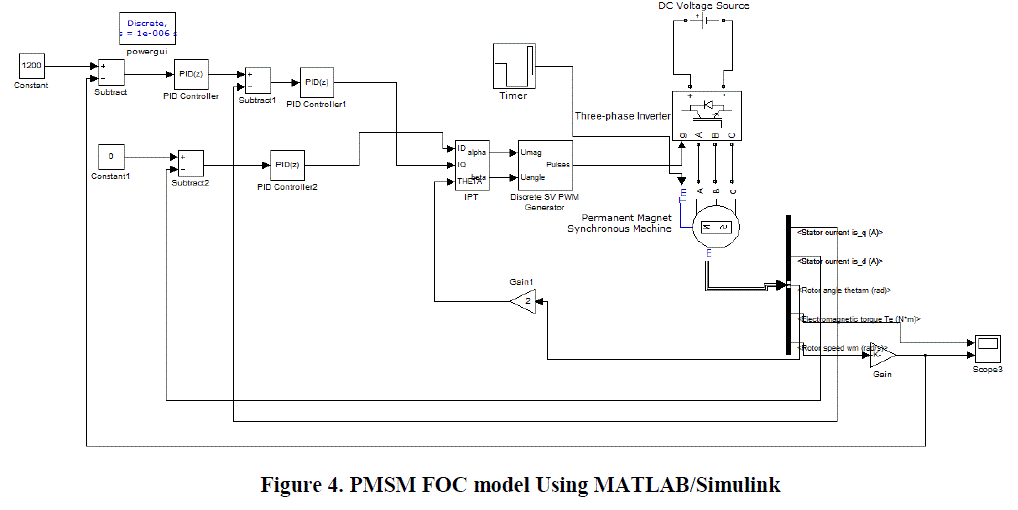 |
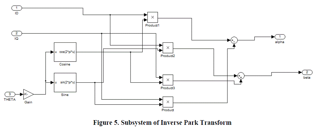
| Sub system: |
 |
| Table for different value of Kp, Kd and Ki of PID controller |
 |
| Output Results: |
| Result for Electromagnetic torque: |
| Here, figure 6 shows the electromagnetic torque for detailed value of torque at a particular time. |
 |
| Here Figure 7(a) Rotor speed for PMSM motor shows the rotor speed for PMSM motor and Figure 7(b) shows
the actual speed and the desired speed graph. |
 |
 |
| From the simulation diagram, we see that the the dc input is given to a three phase inverter, which has its pulse
controlled by inverse park’s transformation block and space vector pulse width modulation block. And the PMSM
motor output is fed to the PID controller which acts as a feedback controller to the IPT block. Where the gain value for
rotor speed is 30/π. |
| Here, from the above figures and table we can see that the rise time , overshoot and settling time is less when
the values of PID controller block 1 is is Kp=400, Ki=1 and Kd=0.001,which is same as PID block 3 and the value of
PID block 2 is Kp=2, Ki=0.1 and Kd=0.001. Here we get the value of Kp, Kd, and Ki using hit and trial method. And at
no load electromagnetic torque remains constant but when we increase the load, torque increases. We know that in case
of synchronous motor speed remains constant even if load is increased. |
CONCLUSION |
| FOC is the standard regulator for Permanent Magnet Synchronous Motors. The chief constituents of this algorithm for
example SVPWM and PID controllers are error less models with constant performance defined over a set of
parameters. With desired simulation parameters and experiments performed on MATLAB 2010a model, the system
proposed validated the better expectations from against the standard architecture. And for the given input parameters
and control variables, the output value was found as desired. |
References |
- Jahns Thomas M., Kliman Gerald B. and Neumann Thomas W., "Interior Permanent-Magnet Synchronous Motors for Adjustable-Speed Drives," IEEE Transactions on Industry Applications, vol.IA-22, no.4 (1986): pp.738-747.
- Sebastian T. Slemon G. and Rahman M., "Modelling of Permanent Magnet Synchronous Motors," IEEE Transactions on Magnetics, vol. 22 (1986): pp. 1069- 1071.
- Pillay P. and Krishnan R., "Modelling of Permanent Magnet Motor Drives," IEEE Transactions on Industrial Electronics, vol.35, no.4 (1988): pp.537-541.
- Hoang Le-Huy.,âÃâ¬ÃÅModeling and Simulation of Electrical Drives using MATLAB/Simulink and Power System Block setâÃâ¬ÃÂ, The 27th Annual Conference of the IEEE on Industrial Electronics Society, IECON '01. Vol. 3 (2001): Page(s): 1603- 1611.
- Chen ming, GaoRanying, Song Rongming,âÃâ¬ÃÂSimulation Study on a DTC System of PMSMâÃâ¬Ã 2011 The 6th International Forum on Strategic Technology978-1-4577- 0399-7111/$26.00 Ãâé2011lEEE
- "Permanent Magnet Synchronous and Brushless DC Motor Drives" by R. Krishna Electrical and Computer Engineering Department Virginia Tech Blacksburg, Virginia, U.S.A.(Textbook)
|