ISSN ONLINE(2319-8753)PRINT(2347-6710)
ISSN ONLINE(2319-8753)PRINT(2347-6710)
Kiran Mudigoudar1, Shanmugam N2, Saddam Hussain. B 3
|
| Related article at Pubmed, Scholar Google |
Visit for more related articles at International Journal of Innovative Research in Science, Engineering and Technology
This paper presents the finite element analysis of the dynamic crack propagation in brittle material namely, Gray cast iron. The analysis is done by using remeshing technique. Dynamic fracture deals with fracture under conditions where inertia forces must be included in the problem formulation. This occurs either under dynamic loading or in the case of static loading as a rapidly propagating crack runs through a structure. In present paper fracture analysis of the RDCB (rectangular double cantilever beam) specimen and the unknown crack tip position and unknown crack velocity is computed during the analysis by the dynamic fracture criterion. According to the new crack tip position, a remeshing technique has been used to simulate the dynamic crack propagation and compared with the experimental result.
Keywords |
| Gray cast iron, Remeshing technique, Dynamic crack propagation, FEA |
INTRODUCTION |
| The presence of a crack can significantly reduce the life of a component or structure. Fracture is considered as the end result of the plastic deformation. As per David Broek [1] et.al, the residual strength of the structure decreases progressively with increasing crack size. Dynamic fracture deals with fracture under conditions where inertia forces must be included in the problem formulation. This occurs either under dynamic loading or in the case of static loading as a rapidly propagating crack runs through structure. As per Ali Fatemi [2] et.al, for crack growth or fracture condition the elastic-plastic fracture mechanics are used to describe the fatigue and fracture process. In this paper for investigation RDCB (rectangular double cantilever beam) specimens were used. To determine the crack growth speed and fracture toughness of materials, usually using the rectangular double cantilever beam specimens. Malluck JF, King WW [3] et.al, used the kanninen’s model for simulation of fast fracture in the DCB specimen. Kanninen MF [4] et.al, the DCB (double cantilever beam) test specimen is used for dynamic analysis of unstable crack propagation and arrest. Simple beam or shear beam theories related theoretical analysis of the RDCB specimens. The applications of beam theory to the dynamic crack propagation are particularly attractive because it is one dimensional analysis. The crack tip stress or strains were cannot predicted by the beam theory and it does provide an accurate account of energy quantities which form the basis of the fracture criterion. Nishioka and Atluri [5] et.al, introduced a moving singular element procedure for dynamic crack propagation analysis. In their method, a special singular element that follows the moving crack tip is used, a special singular element that follows the moving crack tip is used, and during the simulation of crack propagation only the conventional elements immediately surrounding the singular element are distorted. Nishioke and Atluri [6] et.al,carried out the dynamic fracture analysis of RDCB specimen using the moving finite element method. In this paper, a finite element simulation is based on the remeshing technique compatible with the actual dynamic fracture process. Under the fixed displacement loading condition the analysis is done on the RDCB specimen. The analysis results show good agreement with those obtained via the experimental procedures and other numerical techniques. |
DYNAMIC STRESS INTENSITY FACTOR (KI) |
| The stress intensity factor is measure for the stress and strain environment of the crack tip. The stress intensity factor is still meaningful if the of the applied loading, the geometrical configuration of the body and the bulk material parameters in the crack tip region for any motion of the crack tip. For dynamically propagating crack under a steady unsteady state condition, these parameters depend on time, the crack length and the crack tip velocity. The equilibrium stress intensity factor is depends on the current length of the crack, applied load and the crack tip extension. Eslami [7] et.al, calculated the dynamic stress intensity factor in the mixed mode using the complex functions theory. In that after solving the wave equations, the stress and strain fields, also the J-integrals are obtained. Finally using the J-integrals, dynamic stress intensity factors are calculated. |
DYNAMIC FRACTURE TOUGHNESS (KIC) |
| Fracture toughness is the resistance of the material for the crack growth. In a special temperature the magnitude of the fracture toughness is depends on the crack speed and the properties of the material. Weisbrod and Rittel [8] et.al, used the small beam specimens for dynamic fracture toughness test. They present the new methodology which combines experimentally determined loads and fracture time, together with a numerical model of the specimen. They defined the fracture toughness as the value of the stress intensity factor at fracture time. The numerical model is tested by comparing numerical and analytical solutions of the impact loaded beam. They compared directly measured stress intensity factors with the results of the hybrid experimental and numerical calculations. This method is simple to implement, computationally inexpensive and allows testing of large sample sizes, without restriction on the specimen geometry and type of loading. |
REMESHING TECHNIQUE |
| As per the Zur Erlangung des Grades and Vorgelegt Von [9] et.al, remeshing is a key component of many geometric algorithms, including modeling, editing, animation and simulation. As such, the rapidly developing field of geometry processing has produced a profusion of new remeshing technique. As per Pierre Alliez, Giuliana Ucelli, Craig Gotsman and Marco Attene [10] et.al, there is no universal accepted definition for remeshing. It often varies according to the targeted goal or application. Nonetheless, one possible definition could be:”given a 3D mesh, compute another mesh, whose elements satisfy some quality requirements, while approximating the input acceptably”. Quality herein has several meanings. It can refer to the sampling, grading, regularity, size or shape of elements. Often a combination of these criteria is desired in real applications. Some remeshing techniques proceed by altering the input and some will generate a new mesh. |
SPECIMEN AND GEOMETRY |
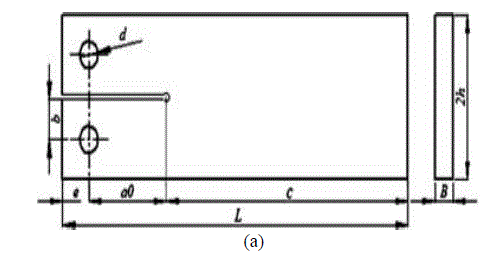
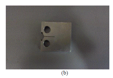
| For the experimentation Gray cast iron material of ASTM number 20 is used. Figure (a) shows geometry of RDCB specimen and figure (b) shows the machined finally ready specimen for fracture test. The RDCB specimen dimensions used are as follows: length L=32.18mm, initial crack length ao=6mm, beam height h=15.45mm, pins diameter d=6.3mm, distance from beam end to pin e=7.43mm, distance from crack plane to pin b=7.03mm and thickness B=12.875mm. The dimensions are in conformity with ASTM E-399 standard. All surfaces shall be parallel and perpendicular to each other with ±0.05mm tolerance. The table shows the properties of the gray cast iron of ASTM number 20. |
 |
 |
EXPERIMENTAL PROCEDURE |
 |
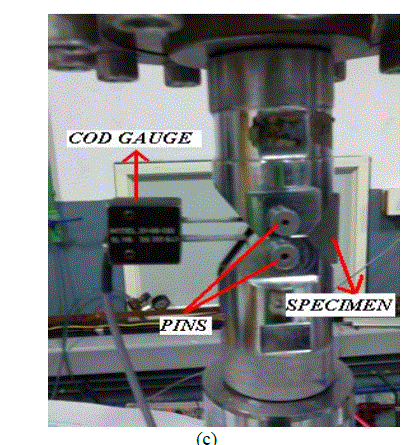
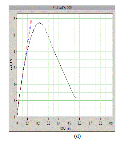
| In the experimentation the specimen is fixed in between the jaws of the testing machine using the pins. The fig.(c) shows the experimental set up for the fracture test. The tensile load is applied on both the fixed ends. The pre-crack starts growing instantly with increasing load. Then finally the crack propagates until the specimen is break in to two pieces. Fig (d) shows the graph which is load verses COD (crack opening displacement). The COD increases slowly with increasing load up to a certain point then after with lower load also COD increases rapidly. The maximum load noticed during the experimentation is 11.52 KN and the COD length is about 5.5mm known from fig (d). |
DETERMINATION OF KIC |
| The goal is to have experimental determination of KIC until we know its value it becomes difficult to determine the size of the specimen through equations (1) (2) and (3) as given below. In many cases KIC of the specimen is guessed depending on experimentation. The specimen dimensions is already known. |
 |
| The fracture toughness of the material is thus obtained is given a tentative name KQ(stress intensity factor). once the value of KQ is known specimen dimensions a,B and W are evaluated through in equations (1) (2) and (3).The test is valid test if all the three equations are satisfied and then KQ becomes KIC. After the calculation all the above equations were satisfied and the KQ becomes KIC. |
NUMARICAL ANALYSIS |
| Finite Element Analysis standard code ANAYS R14.5 has been employed for modeling the problem. The stress intensity for various cracks lengths has been analyzed and it’s shown below. |
| STRESS INTENSITY AT CRACK LENGTH OF 1mm |
 \ \ |
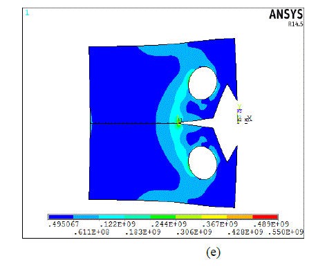
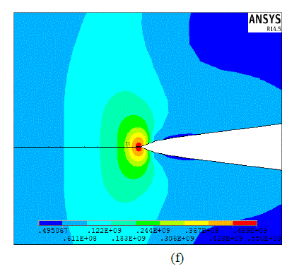
| The figure (e) shows the von-mises stress at the crack length of 1mm from the pre-crack. In the figure (f) shows the zoom view of the crack of 1mm length of stress intensity results is KI = 0.13678E+08 MPa . |
| STRESS INTENSITY AT CRACK LENGTH OF 3mm |
 |
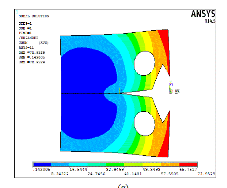
| The figure (g) shows the displacement stress at the crack length of 3mm from the pre-crack. In the figure (h) shows the von-mises stress at the crack length of 3mm length of stress intensity results is KI = 0.18550E+08 MPa . |
 |
| The figure (i) shows the von-mises stress at the crack length of 5mm from the pre-crack. In the figure (j) shows the zoom view of the crack of 5mm length of stress intensity results is KI = 0.25128E+08 MPa . |
 |
| Fig (k) shows the graph in which the stress intensity verses the crack length. The graph is drawn using the values of analysis report. From the graph can conclude that the stress intensity increases with increasing crack length. |
CONCLUSION |
| The problem of dynamic crack propagation in RDCB specimen, made up of Gray cast iron with ASTM number 20, has been analysed. A finite element analysis based on the remeshing technique has been used to simulate the crack growth during the fracture process. The remeshing technique has been preferred among the traditional methods, and this is due to the fact that when it combines with the singular elements it could model the crack tip singularity and conserve it through the crack advancement. |
 |
| In figure (l) the graph shows the comparison of analysis and Experimental results. This is the better agreement that the stress intensity of the analysis results and experimental results are approximately similar in every crack length. From the experimentation, got the stress intensity factor (KQ) is 12.375 MPa that is considered further as the fracture toughness (KIC) value of the material. From the Analysis, got the stress intensity factor (KQ) is 13.67 MPa which is approximately nearer to the experimental value. This procedure, which offers an alternative for determining the fracture behaviour of the materials, also has important advantage such as a better ability to modify the geometry as well as the size of the specimen. It allows the fracture behavour of material in different crack lengths to be analysed in a less cost as compared to the experimentation. |
References |
|