ISSN ONLINE(2319-8753)PRINT(2347-6710)
ISSN ONLINE(2319-8753)PRINT(2347-6710)
Adithya M1, M. M. M. Patnaik2
|
| Related article at Pubmed, Scholar Google |
Visit for more related articles at International Journal of Innovative Research in Science, Engineering and Technology
Reactor pressure vessel is a closed container designed to hold gases or liquids at a pressure substantially different from the ambient pressure. Most of the pressure vessels are designed according to the rules of the ASME Code. The Section VIII, Division 1 and Division 2 are normally used in design. The Divsion 1 corresponds to ‘design by rule’ whereas the Division 2 corresponds to ‘design by analysis’. In this paper, the horizontal pressure vessel supported on saddles is designed and analyzed according to the guidelines given in Div 1 and Div 2. The finite element analysis for different configurations of pressure vessel on saddle supports is done using ANSYS. The stress intensities in various cases are analyzed and the optimal location when the saddles are placed away from heads is considered as the most suitable design for the large horizontal vessels. The effect of stiffening is also considered in three cases. The reduction in stress intensity is found for one of the cases. For this the optimization of thickness was done which resulted huge reduction of weight.
Keywords |
| Reactor pressure vessel, saddle supports, stiffener, optimization, finite element analysis. |
INTRODUCTION |
| A reactor pressure vessel is a closed container designed to hold gases or liquids at a pressure substantially different from the ambient pressure. These vessels are designed to store reactive fluids (eg: acid gas) and sustain chemical reactions that may occur in the vessel. The vessel is generally applied with refractory coating to avoid direct contact of reactive fluids with the shell and thus avoid the reaction with shell material. These types of vessels are mostly used in oil and petroleum industry for storage purposes [3]. These pressure vessels are to be designed carefully to avoid failures which are mostly stress dependent. For this reason it becomes necessary to obtain the stress distribution in the pressure vessels. Hence there is a need to evaluate the operating stresses due to the imposed conditions by analytical methods. Furthermore we also need to understand the significance of these stresses on the structural integrity of the pressure vessel by considering the material properties of the vessel. Knowledge of the material behaviour is necessary not only to ensure that the vessel can withstand the loading but also to make sure that the material has been chosen and utilized in an optimum manner. When supporting the horizontal reactor pressure vessel on saddle supports it is very important to consider the saddle design and its location to support the vessel effectively without failure. The vessel can be supported by placing the saddle close to the head or away from the head. The stiffener rings can be provided on the axis of the saddle or adjacent to the saddle. The stress distributions need to be analysed for the various configurations of supports in operating case as well as hydrotest case. Then the optimal location of saddle with or without stiffening for the applied boundary conditions needs to be decided. |
II. MODEL CONSTRUCTION AND FORMULATION |
| A pressure vessel with inside diameter ‘ID’, tangent to tangent line length of ‘L’ and with ellipsoidal heads is considered. The three dimensional model is made using Solidworks 2012 from the two dimensional drawing. Different configurations of models were made for the purpose of analysis as shown in the below. |
| 1) Pressure vessel Model (Without stiffener rings) |
| a) Saddle placed at given distance (Fig 1-a) |
| b) Saddle placed at ends (Fig 1-b) |
| 2) Pressure vessel Model (With stiffener rings) |
| a) Saddle placed at given distance |
| ïÃâ÷ Stiffener ring on the axis of saddle (Fig 1-d) |
| ïÃâ÷ Stiffener rings adjacent to the saddle (Fig 1-c) |
| b) Saddle placed at ends |
| ïÃâ÷ Stiffener ring on the axis of saddle (Fig 1-e) |
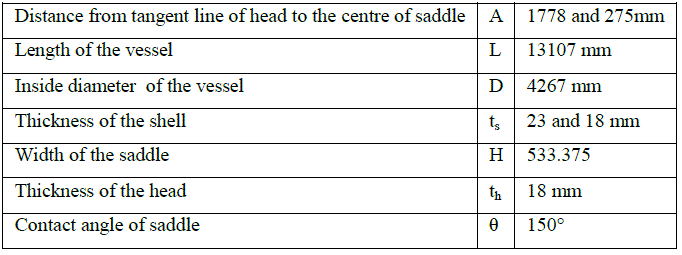
| The details pertaining to the dimension of the pressure vessel are given in the table 1. |
 |
| Fig 1 Different configurations of pressure vessel |
| Table 1 Pressure vessel dimensions |
 |
| It is assumed that saddles are welded to the shell. To anticipate the movements associated with respect to the whole vessel, right side of the saddle is provided with slot as shown in figure 1-g. ASTM A516 is the specification for a range of steels used in the fabrication of industrial pressure vessels and boilers. This steel is used throughout the oil and gas, chemical and power generation industry and can be tested to exceed the specified requirements. Good machinability and forming capabilities is also a feature of ASTM A516 steels. It offers greater tensile and yield strength and can operate in even lower service temperatures. |
| It is assumed that saddles are welded to the shell. To anticipate the movements associated with respect to the whole vessel, right side of the saddle is provided with slot as shown in figure 1-g. ASTM A516 is the specification for a range of steels used in the fabrication of industrial pressure vessels and boilers. This steel is used throughout the oil and gas, chemical and power generation industry and can be tested to exceed the specified requirements. Good machinability and forming capabilities is also a feature of ASTM A516 steels. It offers greater tensile and yield strength and can operate in even lower service temperatures. |
| Table 2 Properties of SA 516 GR 70 Steel |
 |
III. EMPIRICAL APPROACH |
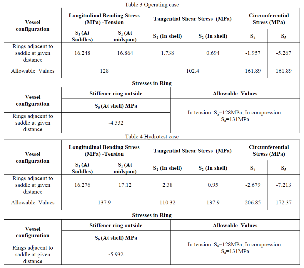
| Structural analysis is probably the most common application of the finite element method. Assumptions are usually made in order to treat the structural system as linear. The assumptions that are considered are: a) The displacement of the structure is so insignificant that under the applied loads, the deformed configuration can be approximated by the un-deformed configuration in satisfying the equilibrium equations. b) The structural deformation is so small that the relationship between strain and displacement remains linear. c) For small deformation, the stress-strain relationship of all structural members fall in the range of Hooke’s law, i.e., it is linear elastic, isotropic and homogeneous. [2] Stress analysis involves determining the relationship between the applied loads on the vessel and the associated response in terms of deflections, stresses, and strains. The purpose of empirical calculation is to approximate the stresses that exist in cylindrical vessels supported on two saddles at various locations. By knowing the stresses, it is possible to design a pressure vessel with a proper stiffening ring which is structurally adequate and economical. The weight of the vessel with fluid acts on the on saddles. The saddle reactions are highly concentrated and induce high localized stresses in the shell. The intensity changes with the distance of the saddles from the vessel end closures that reinforce the shell with their own stiffness. It is difficult to calculate localized stresses in the shell above the saddles initially. Hence Zick’s analysis [15] is used to calculate stresses induced in various parts vessel and saddle. Approximate analysis involving certain empirical assumptions which make the theoretical analysis closely approximate to the test results are done for different configurations of pressure vessel. The calculated stress values for one of the configuration i.e. vessel supported on saddles placed away from head with adjacent stiffener rings is tabulated below for operating case and hydrotest case. |
 |
IV. FINITE ELEMENT MODELING AND STRUCTURAL ANALYSIS |
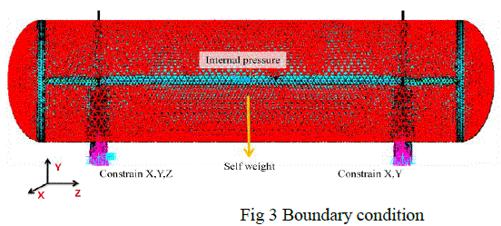
| The finite element analysis is done using ANSYS software. The parasolid model is created using cad software and is imported to ANSYS so that volumes are generated. Solid 187 type element is used in the analysis. This element is used to mesh volumes in ANSYS and the geometry is fully defined by the element nodes. Meshing is done in the ANSYS software and node connectivity between elements in different surfaces has been achieved as shown in figure 2. The mesh size was limited on the basis of computer ability to process the generated equations during solving. The discretized model is then applied with boundary conditions at the solution stage in ANSYS. A boundary condition for the model is the setting of a known value for a displacement or an associated load. To serve its purposeful function, structures are prevented from moving freely in space at certain points called supports. Since the pressure vessel is supported by means of saddle supports, we need to constrain only the required degrees of freedom at the supports. Considering practical application of vessel, initially the model is given with bolts holes on left saddle (fig 1-f) and slots on right saddle (fig 1-g). The master and slave nodes are created for both holes and slots. Then the displacement boundary condition which defines degrees of freedom to be constrained is applied on master nodes only. The pressure is applied on the inner surface of the vessel. Also the self weight of the vessel for both operating case and hydrotest case is considered as shown in figure 3 below. |
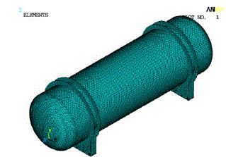 |
| Fig 2 Meshed model |
 |
A. Deflection plots |
| When the deflections are compared in operating and hydrotest cases, the deflection is minimum in the case of vessel placed on saddles away from head with adjacent rings as shown in figure 4. This is due to the additional stiffening provided by the ring stiffeners. |
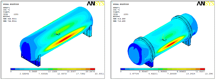 |
| Fig 4 Sample deflection plots in operating case |
B. FEA plots – Vessel |
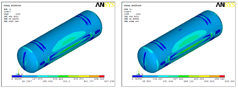 |
| Fig 5 Sample Von-Mises stress and Stress Intensity plots for vessel on saddles placed away from head and rings adjacent to the saddle in hydrotest case |
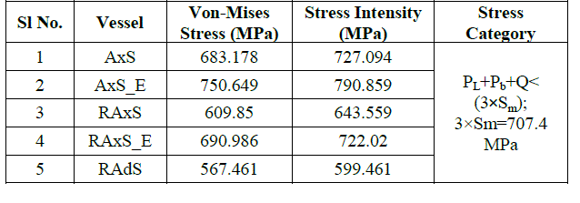 |
| Table 5 Von-Mises stress and Stress Intensity summary |
| From the above plots (fig 5) and table 5, we can infer that the stresses are more near the saddle portion because circumferential bending moments are maximum near the saddles and also along the midspan. The higher values of stress intensities show that the vessel alone is not able to sustain the applied hydrostatic pressure which is almost three times the operating pressure. Hence it is advisable to reduce the hydrotest pressure based on the application of vessel or use stiffener rings or provide an extra saddle at the mid-span of the vessel to avoid flexible centre in case where saddles are placed close to head. |
C. FEA plots –Saddle |
| From the above plots (fig 5) and table 5, we can infer that the stresses are more near the saddle portion because circumferential bending moments are maximum near the saddles and also along the midspan. The higher values of stress intensities show that the vessel alone is not able to sustain the applied hydrostatic pressure which is almost three times the operating pressure. Hence it is advisable to reduce the hydrotest pressure based on the application of vessel or use stiffener rings or provide an extra saddle at the mid-span of the vessel to avoid flexible centre in case where saddles are placed close to head. |
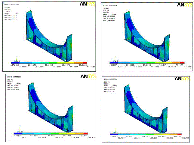 |
| Table 6 Von-Mises stress and Stress Intensity summary (operating case) |
 |
| In the case, where the saddles are placed close to head, the stresses are maximum at the horn of the saddle whereas the maximum stresses occur on the ribs in the case where saddles are placed away from head. In the hydrotest case, (Table 6) we can see that for the vessel without stiffener rings the stress intensities are above the allowable values. This clearly indicates that the use of stiffener rings have considerable effect on the saddle supports as well as on the vessel. The empirical calculations show that the stresses in the vessel are minimum when they are supported near heads. But the stress intensity plot shows that the stress values are very close to the allowable value. From this we can infer that for large horizontal vessels it is not advisable to place the saddles near the heads. From the plots it may be noted that the provision of stiffness near the heads does not reduce the stress considerably instead it results in more rigidness near the head. |
| Table 6 Von-Mises stress and Stress Intensity summary (hydrotest case) |
 |
C. FEA plots –Ring stiffeners |
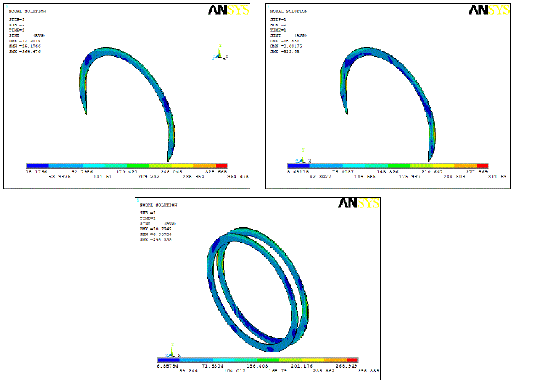 |
| Fig 7 Stress Intensity plots for stiffener rings near fixed saddle in hydrotest case |
| Table 7 Von-Mises stress and Stress Intensity summary (hydrotest case) |
 |
| The stress intensity (Table 7) in the case of vessel placed on saddles away from head with rings on the axis of the saddle is more compared to other configurations. This is because the region or area subjected to internal pressure near the ring is greater compared to other two. Whereas the stress intensity values are lower in the case of saddle close to head with rings on its axis, the region or area subjected to internal pressure on one of side of the ring is more compared to other side of the ring. |
D. Graphical comparison |
 |
Different vessel configurations |
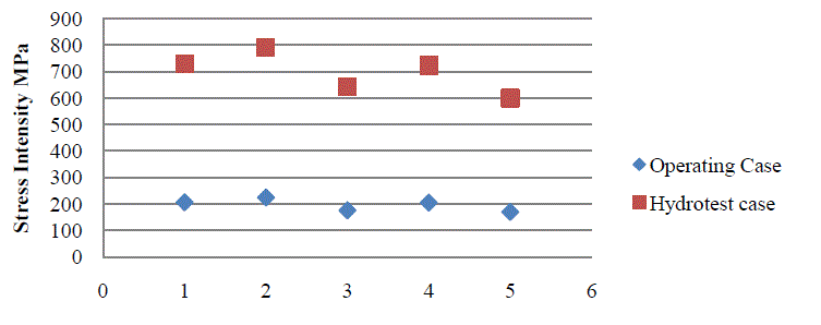
| Fig 8 Stress intensity of vessel |
| The graphical representations show that the pressure vessel supported on saddles away from head with adjacent stiffener rings has lesser values of Von-Mises stress and stress intensity. Hence this can be considered as the best configuration of the vessel for large horizontal vessel. |
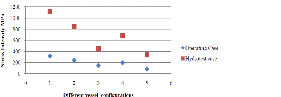 |
| Fig 9 Stress intensity of fixed saddle |
E. Selecting location of the saddle |
| The most economical location and type of support generally depend upon the strength of the vessel to be supported and the cost of the supports and additional stiffening if required. Ring stiffeners can be added at or near the supports when: • the saddles must be located away from the heads • the shell alone cannot resist the circumferential bending. Thin-walled vessels of large diameter are best supported near the heads provided they can support their own weight and contents therein between supports and the heads are stiff enough to transfer the load to the saddles [15]. Considering this, the stress analysis is performed by placing the saddle near the heads with/without stiffening. The advantage of placing fittings and piping in the bottom of the vessel beyond the saddle will also contribute to govern the location of the saddle. By referring to Von-Mises stress and Stress Intensity graphs of saddle support, both are higher when compared to other configurations. Hence to prevent the vessel from flexible centre and rigid ends it is advised to place the saddle away from heads or place an extra saddle at the centre. |
F. Optimization of shell thickness |
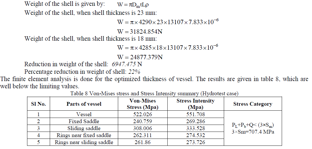
| After comparing the stress values for various configurations of pressure vessel on saddle supports with rings, the vessel supported on saddles placed away from head with adjacent stiffener rings had least stress values and is well below the limiting values in both operating case and hydrotest case. In order to show that provision of additional stiffening reduces the stress in vessel, the thickness of the shell is reduced in view of reducing the weight of the vessel and thus lowers the overall cost. To achieve this, the thickness of the vessel is made equal to ellipsoidal head thickness. Now the constrained optimization method is used to evaluate the reduction in thickness. In constrained optimization method the objective is to minimize the function which is subjected to constraints. In this work the objective is to find the reduction in weight of the vessel when the thickness is reduced which is subject to constraints such as stress and deflection. The volume is kept constant and in turn the inside diameter. |
 |
V. CONCLUSION |
| The behaviour of the vessel on saddle supports with stiffening and without stiffening is analyzed separately. The stress distribution on various locations of saddle and vessel attachments is observed to select the optimal distance of saddle and stiffening. The operating case which is considered at elevated temperature (344°C) simulates the behaviour of the vessel at operating condition. The hydrotest case helps to evaluate the maximum ability of the pressure vessel against the applied hydrostatic pressure at test temperature. Also this helps the designer to decide whether there is a requirement to conduct hydrotest for the actual pressure vessel and to interpret the experimental results with the simulated ones. The comparison of these results helps to provide the most optimized design with an ability to meet the requirements. The empirical approach corresponds to design by rule and finite element analysis corresponds to design by analysis method are adopted and calculations were made according to ASME standards. This shows clearly that the design by analysis is most desirable method to evaluate and predict the behaviour of different configurations of pressure vessel supported on saddle with/without stiffener rings. However in the initial stage the empirical formulae are very much required to decide design variables and limiting values. After analyzing the stress behaviour of the pressure vessel with different configurations of saddle supports with/without stiffening, the location of saddle at distance which is less than the one fourth of the vessel length with adjacent stiffener rings is the most effective one. For this configuration the optimization of thickness is done. The weight of the vessel is reduced considerably by keeping the volume of the vessel constant. 22% weight reduction is achieved for the shell alone. This also shows that addition of stiffener rings helps to reduce the thickness of the shell which in turn helps in saving lot of material and cost associated with it. |
ACKNOWLEDGMENT |
| The authors would like to thank Dr.Suresh.P.M, Professor and Head of the Department, Mechanical Engineering Department, KSIT, Bangalore, for his valuable support in carrying out this work. |
References |
|