ISSN ONLINE(2319-8753)PRINT(2347-6710)
ISSN ONLINE(2319-8753)PRINT(2347-6710)
Yogesh Pal1, Naushad Ahmad Ansari2, M. Zunaid3
|
| Related article at Pubmed, Scholar Google |
Visit for more related articles at International Journal of Innovative Research in Science, Engineering and Technology
Rate of heat transfer increases by several folds with the increase in the surface area of heat exchangers, in practice this is often achieved by having fins at the surface of heat exchangers. The objective of the present study was to visualize the air flow around perforated circular finned tube (PCFT) through computational fluid dynamics (CFD). The air-side flow was visualized through simulation in fluent. Visualization of flow of air around the tube and fin for various cases were studied. These cases include the different positions of perforations on fins with respect to stagnation point. The different positions selected for perforations with respect to stagnation point are no holes and holes at an angle of 90 degree, 100 degree, 110 degree, 115 degree, 120 degree, 140 degree, 145 degree, 150 degree, 160 degree, and 170 degree. Gambit was used for construction of geometry and k-epsilon model was used for flow visualization. The perforation at an angle of 120 degree with respect to stagnation point was found to be the best location because recirculation of flow at this location found to be least. However perforations at the angles greater than 90 degree but less than 170 degree were effective in reducing the recirculation
Keywords |
| CFD; Flow visualization,Perforated circular fins, Recirculation, Stagnation point |
INTRODUCTION |
| Finned surfaces are commonly used in practice to enhance heat transfer, and they often increase the rate of heat transfer from a surface several fold. There are a variety of innovative fin designs available in the market, and they seem to be limited only by imagination. The closely packed thin metal sheets attached to hot water tubes increase the surface area of convection and thus rate of convection heat transfer from the tubes to the air many times [1]. Heat transfer characteristics at the air side have been studied with various fin geometries with both experimental and analytical methods to improve the performance of the finned-tube heat exchanger [2]. In many applications circular finned tubes are being used due to their low manufacturing cost and in addition to it circular finned tube heat exchangers are also known with their high efficiency [2,3].Many researchers have investigated various techniques to enhance the convective heat transfer performance of circular finned-tubes heat exchangers. Perforated circular finned tube (PCFT) can reduce the air-side recirculation region behind the finned tube and thus enhance the convective heat transfer performance. The separation and detachment of air flow were delayed by introducing the perforations at the flowseparation locations on the finned tube, and the recirculation region was thus decreased thereafter [4]. Number of perforations on a circular finned tube affected both the convective heat transfer coefficient and pressure drop at the air side. The increase in the convective heat transfer coefficient at the air side by the introduction of the perforations was considered to be mostly related to the reduction of a recirculation region [5,6]. CFD is a science that can be helpful for studying fluid flow, heat transfer, chemical reactions etc. by solving mathematical equations with the help of numerical analysis [7]. CFD employs a very simple principle of resolving the entire system in small cells or grids and applying governing equations on these discrete elements to find numerical solutions regarding pressure distribution, temperature gradients and other flow parameters in a shorter time at a lower cost because of reduced required experimental work [8,9]. The air-side flow was visualized through simulation in fluent 6.3.26. In order to compute complex airflows through a fin-and-tube heat exchanger, CFD assumes greater importance [10].Chan HyeokJeong et al. developed a new shape of plate fin heat exchanger by applying ceases and holes on the plate fin has observed thatthe more the crease angle (q) increases, the more the crease cycle (l) decreases, and the more the number of holes (N) increases, the more the pressure loss and heat transfer performance increase together [11]. |
| The objective of the present study was to visualize the air flow around perforated circular finned tube (PCFT) through computational fluid dynamics (CFD) only for 2-holes case because Lee et al. [4] investigated that in the case of the 4- hole PCFT there is a greater pressure drop which might be due to excessive flow disturbances produced by multiple perforations. |
FLOW VISUALIZATION PROCEDURE |
| Visualization of air flow around the tube and fin for various positions of perforations on fins with respect to stagnation point are studied. The positions selected for perforations are no holes and holes at an angle of 90 degree, 100 degree, 110 degree, 115 degree, 120 degree, 140 degree, 145 degree, 150 degree, 160 degree, and 170 degree with respect to stagnation point. Visualization of flow was carried out in following steps. |
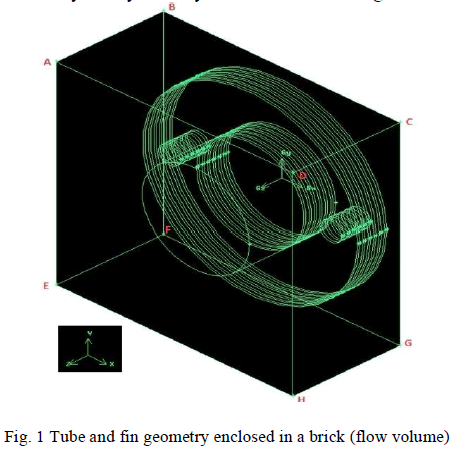
| 1. Physical model- the construction of geometry was done on gambit 2.4.6. The geometry consisted of a tube of length (along z-axis) 8 centimetres and radius 5 centimetres on which six circular fins were attached of radius 10 centimetres and thickness 0.2 centimetres. Spacing between the fins were taken at 0.5 centimetres. The whole apparatus was then enclosed in a brick of dimensions 22×22×10 centimetres. Due to uniform air flow parallel to fins, flow visualization was done for only for symmetry face as shown in figure below: |
 |
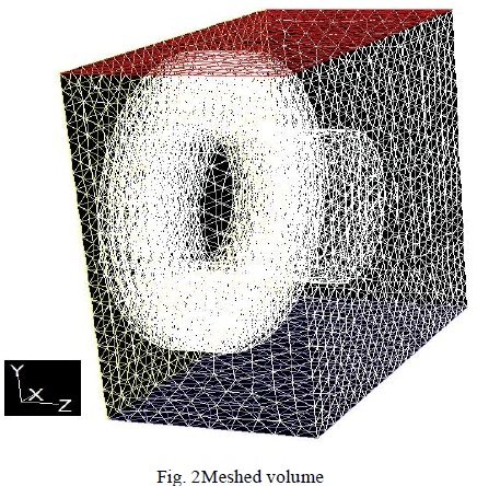
| 2. Boundary conditions-to simulate the air flow boundary conditions have been given to the required faces. In figure 1, face EFGH represents the velocity inlet, face ABCD represents pressure outlet, face BCGF represents symmetry and rest faces i.e. CDHG, ADHE, AEFB, and faces of tube and fins are set as wall. After generating the required volume, meshing was generated as shown in figure 2. |
 |
| 3. Simulation- after exporting a mesh file from gambit by selecting solver as fluent 5/6. The mesh file was read on fluent 6.3.26. Scale factor was applied to have length of grids in centimetres. After that k-epsilon model was selected. Thetransport Equations for the Standard k-epsilon Model are as follows: |
 |
| The turbulence kinetic energy, k, and its rate of dissipation, Ãâ°Ãâº, are obtained from these equations. In these equations, Gk represents the generation of turbulence kinetic energy due to the mean velocity gradients, Gb is the generation of turbulence kinetic energy due to buoyancy, YM represents the contribution of the fuctuating dilatation in compressible turbulence to the overall dissipation rate, C1Ãâ°Ãâº, C2Ãâ°Ãâº, and C3Ãâ°Ã⺠are constants.sk and seare the turbulent Prandtl numbers for k and Ãâ°Ãâº, respectively. Skand SÃâ°Ã⺠are user-defined source terms. |
| Fluid selected as air whose density= 1.225 kg/m3 and viscosity= 1.7894e-05 kg/m-s. Operating conditions were set as pressure= 101325 Pascal and temperature = 300 K. Velocity of air at inlet= 10 m/s which is normal to face (along positive y-direction), turbulent kinetic energy as 1 m2/s2, and turbulent dissipation rate as 1 m2/s3. Zero gauge pressure was set at the face ABCD. Flow was initialized with the velocity inlet face then iterations were performed until convergence was formed. |
EXPERIMENTAL RESULTS |
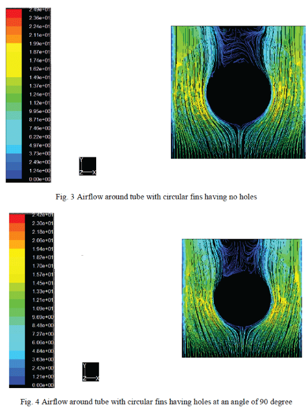
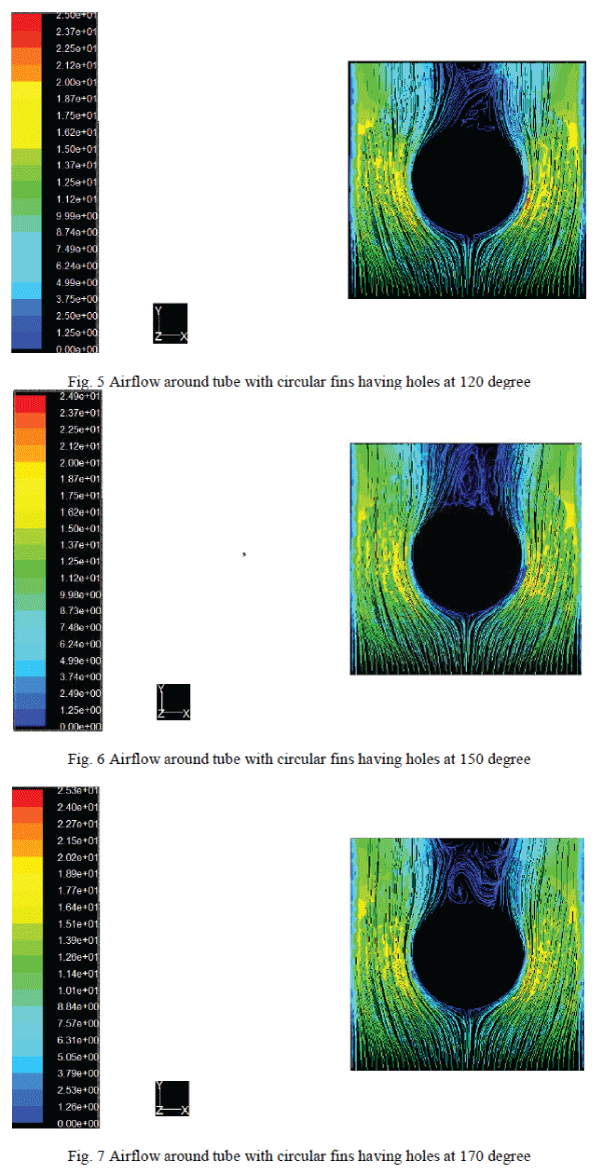
| After displaying velocity path lines, flow of air around the tubes and fins could be visualized. Some important figures are shown below: |
 |
 |
| From figure 3 which was the case of plane fins, it can be seen that there is separation and detachment of air flow from the tube at an angle of approximately 120 degree with respect to stagnation point. In the case of two holes at an angle of 90 degree i.e. figure 4, it can be seen there is more recirculation of air flow around fins as compared to the case of fins without holes. As the angle increases beyond 90 degree, recirculation is decreasing that can be observed in figure 5 i.e. the case of holes at 120 degree in which recirculation is disappeared to a greater extent. As the angle further increases which is closed to 170 degree, recirculation is found to be more than the case of plane fins, this can be observed in figure 7.According to Lee et al. [4] the separation and detachment of air flow were delayed by introducing the perforations at the flow-separation locations on the finned tube, and the recirculation region was thus decreased thereafter. As we see in figure 3 that flow separation is taking place at an angle of approximately 120 degree with respect to stagnation point in the case of plane fins. Therefore, perforations at 120 degree on fins are most effective in reducing the separation and detachment of air flow. Hence, the above result could be validated. |
CONCLUSION |
| From above discussion it can be concluded that the perforations at an angle of 120 degree with respect to stagnation point is the best location because recirculation of air flow is vanishing up to a greater extent in this case. Hence there could be more convective heat transfer obtained between fluid flowing inside the tube and air flowing over the tube. This result might be helpful in reducing size of heat exchangers because with perforations on the fins, a higher value of convective heat transfer coefficient could be obtained as compared to the plane fins. Also, further investigations are recommended to study the effect of size of hole on recirculation region. |
References |
|