ISSN ONLINE(2319-8753)PRINT(2347-6710)
ISSN ONLINE(2319-8753)PRINT(2347-6710)
| M Ramesh M Tech, Department of I C Engines, Vel Tech Rangarajan Dr. Sagunthala R&D Institute of Science And Technology Avadi, Chennai, India |
| Related article at Pubmed, Scholar Google |
Visit for more related articles at International Journal of Innovative Research in Science, Engineering and Technology
Customer satisfaction is one of the key factors for success of any product in the market. Typically Customers who purchases a new passenger look for the following features, (1) High Fuel efficiency (2) More life i.e High durability of the components (3) Less maintenance i.e less service turn around (4) Less NVH (Noise, Vibration and Harshness), Present day customers are more irritant to noise and vibration. In order to achieve above features inherently, a better Product development from the design to production stage is essential.All key parameters that influence the Product performance should be focussed on the all stages of Product development. This project work will essentially discuss on the mechanical development aspect of an engine, which mainly constitutes durability and reliability of the engine. Engine oil consumption is an important source of hydrocarbon and particulate emissions in automotive engines. Oil evaporating from the piston-ring-liner system is believed to contribute significantly to total oil consumption, especially during severe operating conditions. As a part of the effort to comply with increasingly stringent emission standards, engine manufacturers strive to work on EMS calibration strategies. This requires the advancement of the understanding of the characteristics and driving mechanisms of various applications. This paper will discuss certain parameters of the below critical areas on a two cylinder gasoline engine, (1) Protection on Engine to have oil consumption (2) Protection on Engine to avoid overheating (3) Engine Calibration
INTRODUCTION |
| A. MECHANICAL DEVELOPMENT |
| Many different types of engine tests are performed within the industry, some more common than others. The six principal tests and relevant applications are listed as follows: |
| a. Durability (Design Validation Test) |
| i. Steady load and speed operation |
| ii. Load cycling |
| iii. Speed cycling |
| iv. Thermal shock cycling |
| v. Component development |
| b. Performance |
| i. Power curves |
| ii. Governor curves |
| iii. Lubrication oil consumption |
| iv. Flow measurements |
| v. Heat balance |
| vi. Emissions measurements |
| c. Lubricants and Fuels |
| i. Automotive lubricants |
| ii. Marine lubricants |
| iii. Black sludge formation |
| iv. Intake valve deposits |
| v. Combustion chamber deposits |
| d. Specialized Investigations and Testing |
| i. Rig testing (e.g., bearings, antifreeze, erosion) |
| ii. Simulated or environmental testing |
| iii. Photo elastic stress measurements |
| iv. Strain gauge testing |
| v. Flywheel burst testing |
| e. Exhaust System Testing |
| i. Vehicle cycle simulation |
| ii. Steady state |
| f. Catalyst Ageing |
| i. Vehicle cycle simulation |
| ii. Steady state |
| iii. Accelerated ageing |
| iv. Light-off efficiency tests |
| v. Sulfate release tests |
| Of course, there are other specific test types, but the preceding list covers the vast majority of test types that are likely to be encountered in the day-to-day testing undertaken by the research student, automotive engineer, and engine test technician. |
| Fully transient tests and, indeed, automatic mapping software programs are disciplines worthy of additional study. However, to glean the maximum useful repeatable data from all forms of transient testing, it is essential to have a full understanding of and experience with steady-state test types. Mathematical modeling of engine functions isan essential element in the design and development of new engine types. The accuratecross-correlation of modeled data with actual running data enables the leading manufacturersto move ahead of the opposition rapidly and to obtain clear market gains. |
| B. DEFINITIONS |
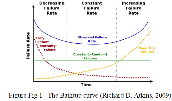
| The popular terms "durability" and "reliability" often are confused. Therefore, before discussing durability tests in depth, it is necessary to define the correct meaning of each term. |
| Reliability-The capability of an item to perform a prescribed task under defined conditions for a predetermined period of time. |
| Durability-The capacity of an item to reach a designed life |
 |
| C. INCREASING THE SEVERITY OF THE TEST |
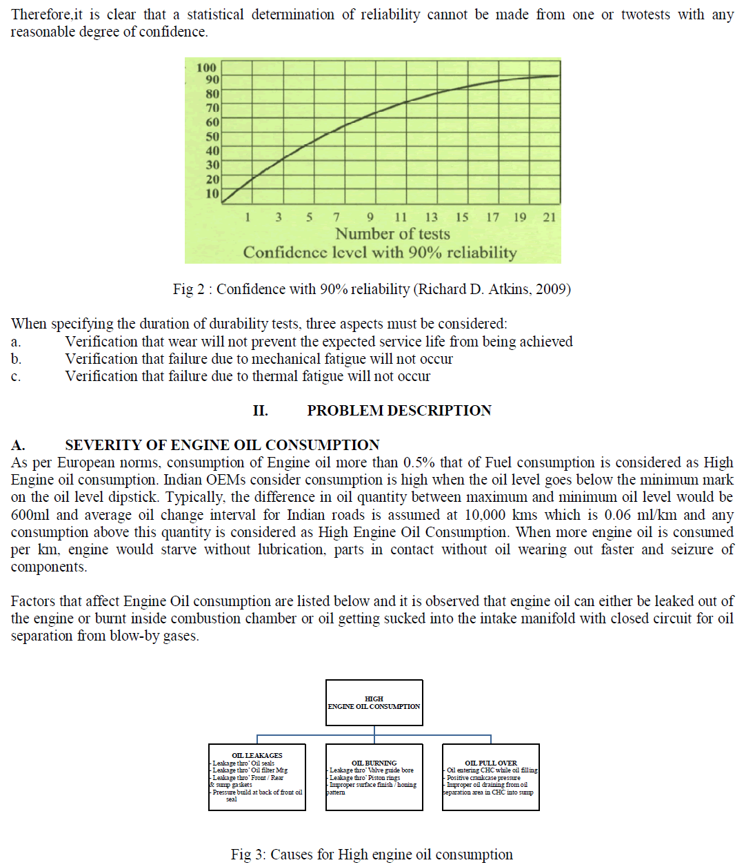
| Some manufacturers increase the severity of their tests by including test conditions that are more severe than those encountered in normal service. These may include overfueling, over-speed, advanced timing to increase cylinder pressure, extreme ambient conditions, and so forth. These tests are of value in reducing the time required to complete the test series, increasing the confidence level in the results when related to normal service, or a combination of both. However, the specification of such tests requires extreme care and normally can be achieved only by reference to historical data. It is a simple matter to specify tests of extreme severity that lead to early failure and therefore cannot be related to normal service. Development on this basis results inthe engine being grossly over-designed for its intended application and hence is non-competitive. Early in a new engine program, at least two durability tests of 1000-hours duration should be undertaken. The objective of this work is to demonstrate that no major deficiencies are present in the design of the revised engine. Classical statistical analysis states that for tests carried out, |
| CL = 1 - Rn |
| where, |
| CL = confidence level |
| R = reliability |
| N = number of tests completed without failure |
| From this, it can be seen that to demonstrate a reliability of 90% with a confidence level of 90%, a total of 22 tests is required. For the same reliability, one test gives a confidence level of 10%, while two tests increase this level to 19%. |
 |
| B. SEVERITY OF ENGINE OVERHEATING |
| The primary purpose of the engine cooling system is to remove the heat absorbed by the engine assembly as a result of the combustion process, as well as friction heat generated within the engine assembly as components move against each other at high speeds. |
| The peak burned gas temperature in the cylinder of an internal combustion engine is of order 2500 K. Maximum metal temperatures for the inside of the combustion chamber space are limited to much lower values by a number of considerations, and cooling for the cylinder head, cylinder, and piston must therefore be provided. These conditions lead to heat fluxes to the chamber walls that can reach as high as 10 MW/m2 during the combustion period. However, during other parts of the operating cycle, the heat flux is essentially zero. The flux varies substantially with location: regions of the chamber that are contacted by rapidly moving high-temperature burned gases generally experience the highest fluxes. In regions of high heat flux, thermal stresses must be kept below levels that would cause fatigue cracking (so temperatures must be less than about 4000C for cast iron and 3000C for aluminum alloys). The gas-side surface of the cylinder wall must be kept below about 1800C to prevent deterioration of the lubricating oil film. Solving these engine heat-transfer problems is obviously a major design task. Major modes of heat transfer seen in cooling system are conduction, convection and radiation. |
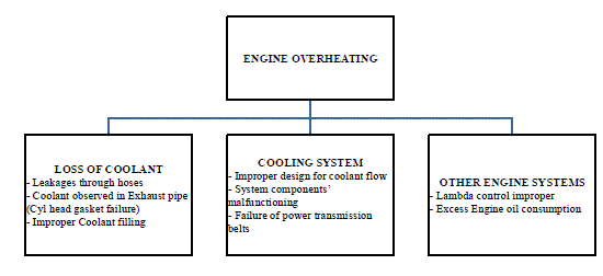 |
| Fig 4 : Causes for Engine overheating |
| C. SEVERITY OF ENGINE CALIBRATION |
| When examining the historical development of car engines, two trends can be observed.On the one hand, engine performance has continuously increased, while on theother – due to the demands of emission-control legislation – the emission of harmfulpollutants has gradually decreased. The simultaneous pursuit of these two developmentobjectives has only been possible by virtue of an enormous degree of systemcontrol on the engine. |
| It is therefore no longer sufficient, as was once the case, to control only fuel-injection and ignition components. Gasoline engines with the full range of technology currently available are equipped with a large number of supplementary systems such as exhaust-gas recirculation or evaporative-emissions control or limp-home mode. In future, other systems, such as variable valve timing, that are not as widely used at present due to cost considerations, will become increasingly widespread. The components of all these systems have to be controlled so as to achieve optimum engine operation under all conceivable conditions. Gasoline engines with direct fuel injection pose particularly demanding requirements in this regard. Consequently, complex electronic systems are indispensable for the management of gasoline engines. With the startlingly rapid progress in semiconductor technology, electronic control units have become more and more powerful so that complete gasoline- engine management systems. |
| A limp-home mode protects the engine from engine overheating due to various reasons and brings the vehicle limphome condition. There are various Calibration strategies that are being followed by OEMs to bring the vehicle to this mode. This paper will explain a cost effective, simple strategy that will keep the engine and hence the vehicles safe under severe operating conditions and protect through limp-home operation. |
METHODOLOGY / EXPERIMENTAL SET-UP |
| A. METHODOLOGY – PROCESS FOR DETERMINING ENGINE OIL CONSUMPTION |
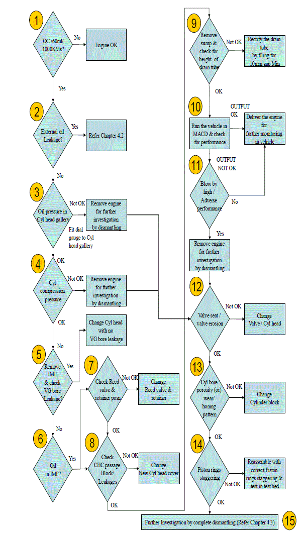 |
| Fig 5 : Process for determining Engine oil consumption |
| B. METHODOLOGY – PROCESS FOR DETERMINING EXTERNAL OIL LEAKAGE |
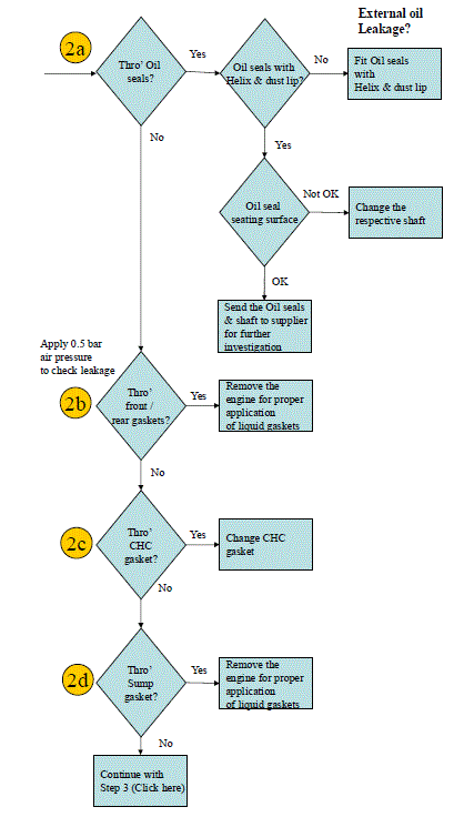 |
| Fig 6: Process for determining External oil leakages |
| C. METHODOLOGY – PROCESS FOR INVESTIGATION ON ENGINE LEVEL BY DISMANTLING |
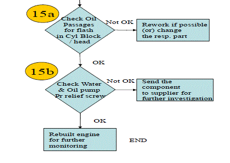 |
| Fig 7 : Process for investigation on engine level by dismantling |
DISCUSSION OF THE PROPOSED WORK |
| A. STUDY ON PRESENT DESIGN AND POSSIBILITY OF IMPROVEMENTS |
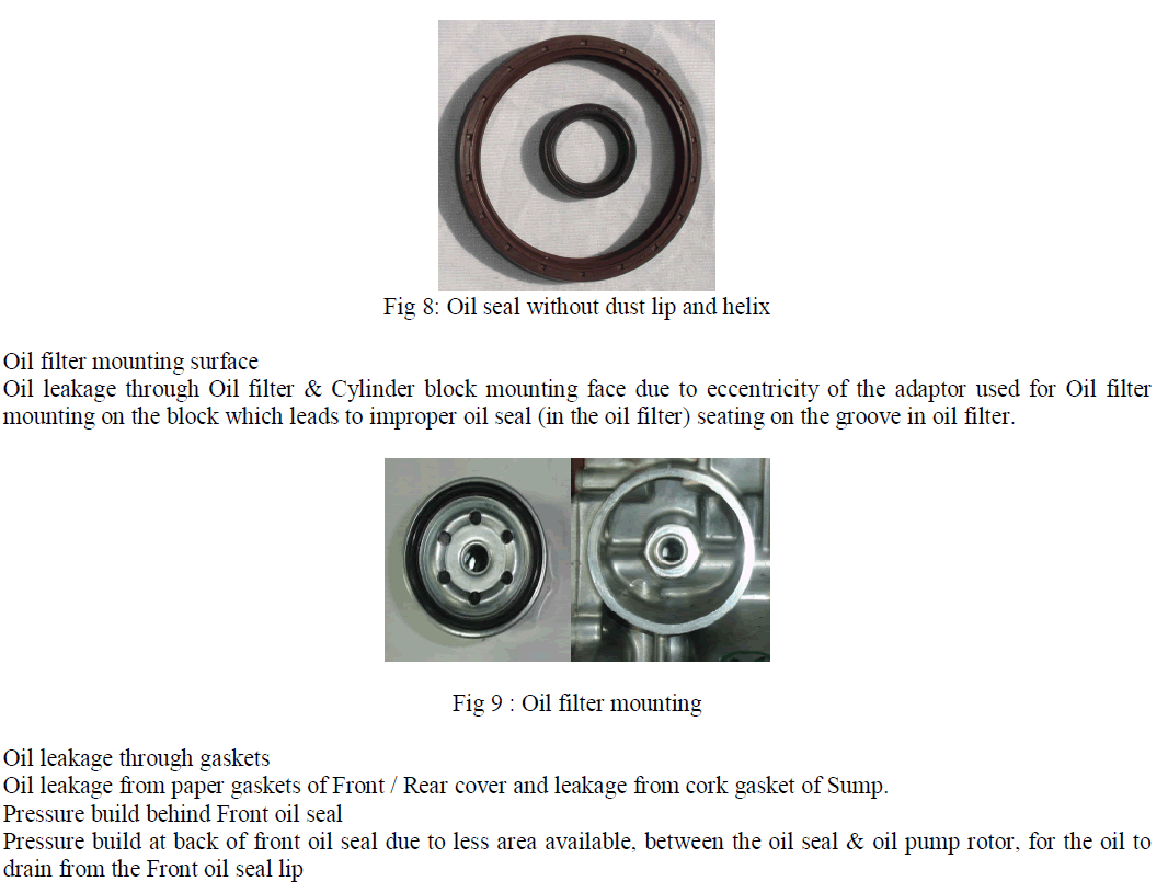
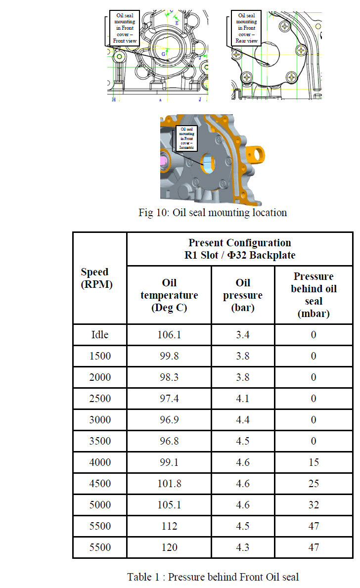
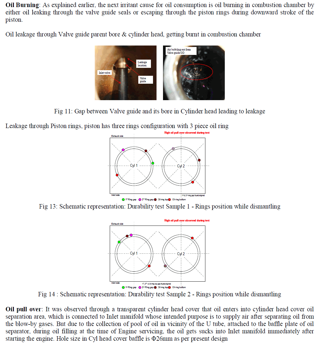
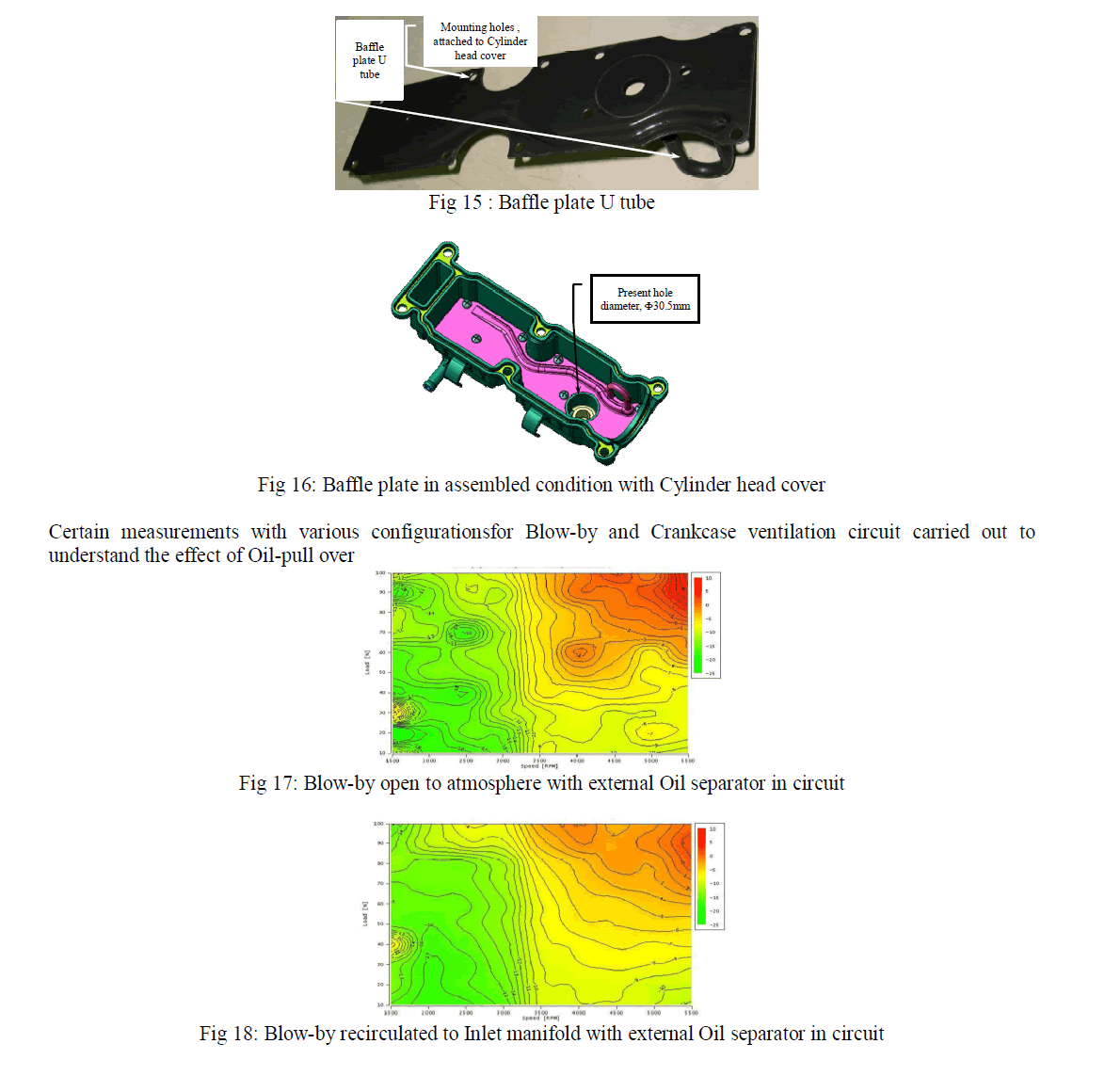
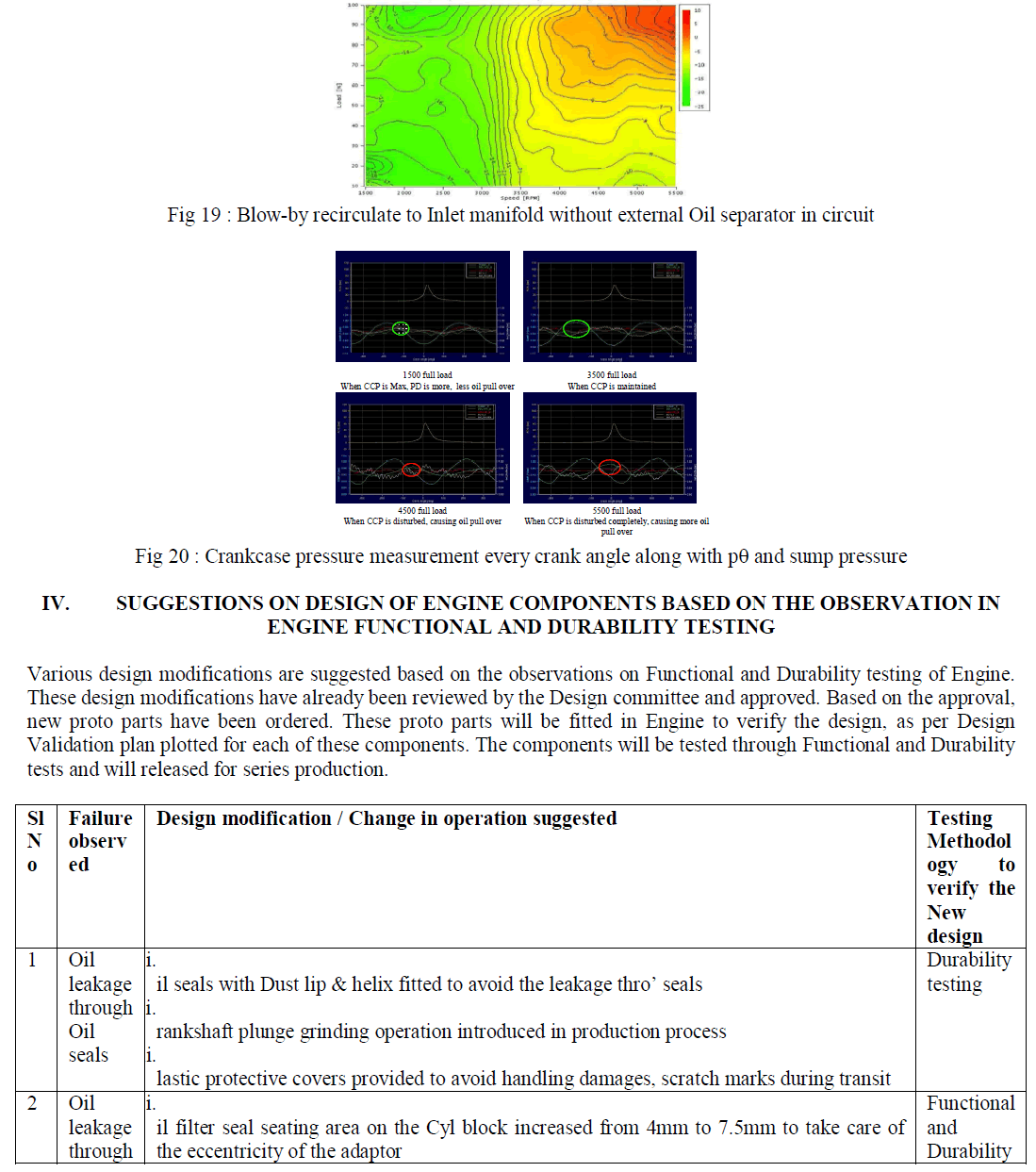
| Oil leakage: As we have seen, Oil leakage is one of the reasons for engine oil consumption, we will try to look into certain design features of engine components which are prone to oil leakage. Oil seals and mounting surface Oil leakage from Front & Rear crank oil seals can be due to high circumferential speed of crankshaft when oil is being pushed out through the seals. Also, environmental dust is able to reach the sealing area, damaging shaft / seal and consequently leading to oil leakage. |
| On closer perspective, Crankshaft oil seating surface with grind tool marks leads to threading action & hence leading to oil leakage through the threading path traced by the oil during the rotation of crankshaft. |
 |
 |
 |
 |
 |
 |
CONCLUSIONS |
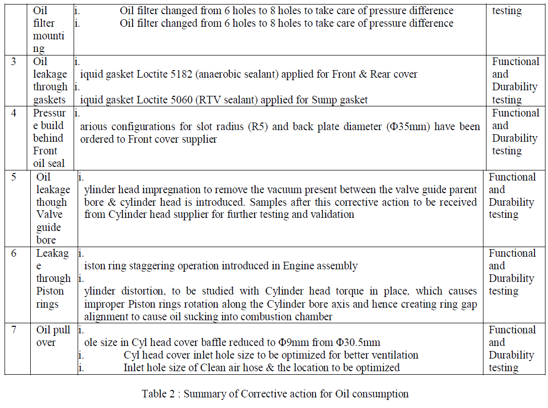
| The influence of various parameters for High Engine oil consumption is studied and based on benchmark and experience, corrective actions have been suggested. All the Design modifications suggested was approved by the committee. Proprietor drawings are modified and design modification in supplier drawings are released and advised respectively to supplier for proto component manufacturing. A lead time of 2 to 3 weeks will be needed for proto parts receipt. Engine testing is planned after the component receipt. All these components will be monitored for its performance and drawings to series production will be released. |
References |
|