ISSN ONLINE(2278-8875) PRINT (2320-3765)
ISSN ONLINE(2278-8875) PRINT (2320-3765)
| Navuday Sharma PG Student, Dept. of Aerospace and Avionics, Amity University, Noida, Uttar Pradesh, India |
| Related article at Pubmed, Scholar Google |
Visit for more related articles at International Journal of Advanced Research in Electrical, Electronics and Instrumentation Engineering
The Finite Element Method (FEM) introduced by engineers in late 50's and 60's is a numerical technique for solving problems which are described by Ordinary Differential Equations (ODE) /Partial Differential Equations (PDE) with appropriate boundary/initial conditions or to solve problems that can be formulated as a functional minimization. FEM provides greater flexibility to model complex geometries. It can handle general boundary conditions and variable material properties. It has a solid theoretical foundation which gives added reliability and makes it possible to mathematically analyze and estimate the error in the approximate solution. This paper gives an introduction and methodology to solve a PDE using FEM in 1D and 2D in the simplest way possible such that the young researchers who has less mathematical or engineering background can also understand this technique. Only Poisson equation is solved in this paper. The result of the solution the PDE‟s is also shown computationally using the open source software of FEniCS.
Keywords |
| FEM 1D, FEM 2D, Partial Differential Equation, Poisson equation, FEniCS |
INTRODUCTION |
| Equations like Laplace, Poisson, Navier-stokes appear in various fields like electrostatics, boundary layer theory, aircraft structures etc. So with solutions of such equations, we can model our problems and solve them. To solve such PDEâÃâ¬ÃŸs with FEM some prerequisites are required. Every PDE has strong form and weak form. The strong form of PDE, implies that the relationship must be satisfy at every mathematical point in the domain. Solving the strong form is not always efficient and may not give smooth solutions for a particular problem. Although it may give the accurate result but obtaining the solution is a difficult task. This is true especially in case of complex domains and/or different material interfaces etc. Moreover, incorporating boundary conditions is not so easy. |
| In order to overcome the above difficulties, weak formulations are preferred. They reduce the continuity requirements on the approximation and allow to construct basis or trial functions which are mostly simple polynomials (generally taken as Lagrange polynomial). Weak forms never give accurate solutions because of the reduction in the requirements of smoothness and weak imposition of boundary conditions. But obtaining the solution becomes an easy task. After that error minimization can be done to remove the inaccuracies obtained in the weak form results. |
| Improving the accuracy of a solution in weak formulations depend upon the type of problem you are solving. In some cases, for example elliptic problems, only mesh refinement is good enough and but when weak formulations are applied to Stokes and Navier-Stoke flows, one needs to use efficient stabilization techniques, along with mesh refinement, to get accurate results. The accuracy can also be improved by using higher-order basis functions. The whole idea of FEM revolves around choosing the appropriate trial or basis functions. A basis function is an element of a particular basis for a functionspace. Every continuous function in thefunction space can be represented asalinear combination of basis functions, just as every vector in a vector space can be represented as a linear combination of basis vectors. |
| This paper includes functions in L2(I) which are known as square-integrable function. It is a real orcomplex-valued measurable function for which the integral of the square of the absolute value is finite. Thus, if |
 |
LITERATURE SURVEY |
| The Finite Element Method is one of the most important techniques in development of computation methods. It has evolved from solving structural engineering problems to almost every domain in science and technology. FEM algorithms are implemented in Finite Element Analysis and engineering problems are solved using softwares like ANSYS, SAMCEF etc. To analyze frame structures, two classical beam theory are used, namely, Euler-Bernoulli theory and Timoshenko beam theory. The formulation of element stiffness and mass matrices using these two theories is based on FEM. Current research is done in the field of finite element shell analysis. For large structural problems, the structure is divided into many parts and local matrices are being developed for each substructure. The local matrices are then combined to get a global matrix of the system and then error minimization is done. The same methodology is followed in this paper to solve the Poisson Equation. |
SOLUTION OF TWO POINT BOUNDARY VALUE 1D PROBLEM USING FEM |
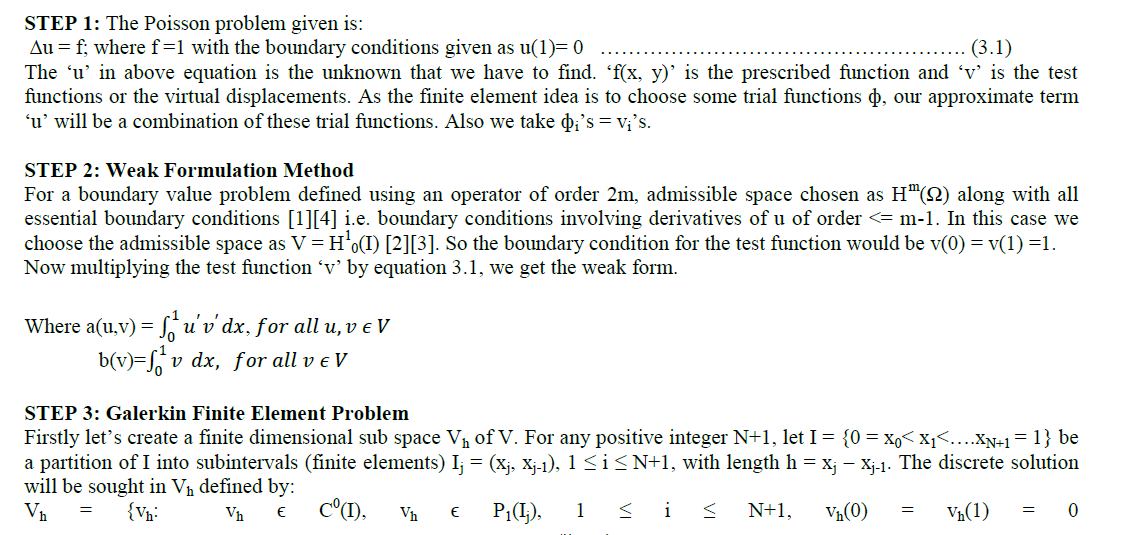 |
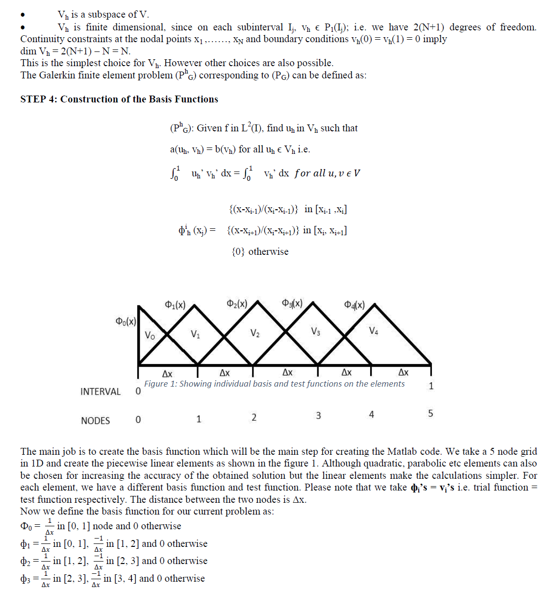 |
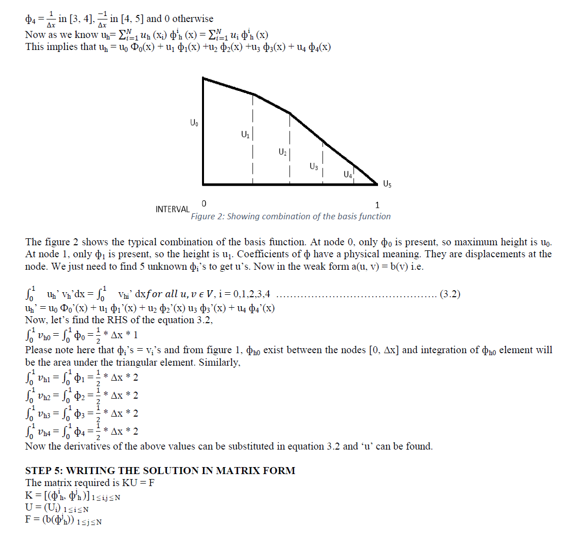 |
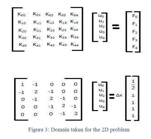 |
FINITE ELEMENT METHOD IN 2D |
| FEM is actually used for solving 2D problems. If a problem is given in 1D with some boundary conditions, it could be integrated simply and boundary conditions can be imposed. But when a 2D problem is given, then FEM is required. This paper presents FEM in 1D, just to explain the methodology of FEM. Finite element method formulation in 2D would be same as in 1D. The only difference is, we have to make the mesh in a plane instead of making the elements in 1D. We can use linear, quadratic or cubic functions for constructing the mesh. The most important part of FEM is choosing the trial functions. We chose simple functions which are easy polynomials on each element. The elements chosen for 1D FEM were linear but in 2D we choose triangular elements. In 1D, when we were using linear elements, we had triangular basis function but in 2D we will have pyramidal basis function. At any node in the 2D mesh, the pyramid function ̉̉1 is 1 and zero at all the other points just like we do in hat functions (basis function in 1D). |
 |
 |
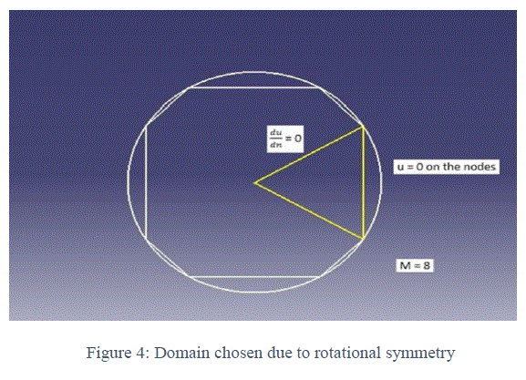
| LetâÃâ¬ÃŸs take a circular domain to solve the problem. In the circular domain, we have to approximate the curved boundaries by straight lines. That would make our domain as a polygon. So draw the polygon with about eight sides and u=0 is true on the eight nodes. Now letâÃâ¬ÃŸs divide our domain into 8 triangles or M triangles for M sided polygon. Now we need to work only on one triangle. By rotational symmetry, weâÃâ¬ÃŸll have the same results for all the triangles. So our domain becomes just one triangle. In that triangle, we have u = 0 boundary condition at two nodes and on the edge of the triangles we have Neumann boundary condition, du/dn =0 Now the coordinates of the triangle given in figure 3 can be calculated. |
| Now we create the mesh on the triangle. For that, we divide the center line of the triangle into N parts with distance between each part as „hâÃâ¬ÃŸ. Using these N points on the line, we form the mesh as shown in figure 4 and number the nodes and the triangles. |
| Now if we can get the coordinates of the mesh points, we could put them in a code and solve the problem using FEM. If we use N = 4, then we would get 13 nodes and 14 triangles and we know the coordinates of every node. We can create a Matlab code for solving the problem using FEM. The code will be needing the list of the coordinates of the nodes (P) and the list of the triangles (T). The triangle tells us the threenode numbers and the list P gives us their positions. |
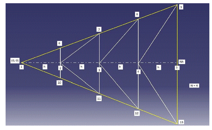 |
| P = (0, 0), (h, 0), (2h, 0)………………… |
| T = (1, 2, 6), (2, 7, 6)…………………. |
| Now the Matlab code will create the stiffness matrix „KâÃâ¬ÃŸ and put in the boundary conditions i.e. u = 0 at node 3, 5, 9, which implies that at the whole edge, u = 0. After that, we can solve the matrix, KU = F. The code is creating „KâÃâ¬ÃŸ and „FâÃâ¬ÃŸ for us. |
| This is how the mesh is created and the Matlab code works for us. Now for better accuracy, we could have chosen P2 elements instead of P1 elements or we could have increased M i.e. number of triangles would have increased. |
| Equation (4.1) is the strong form of our problem. Now for the weak form, we have to multiply it with a test function and integrate by parts. |
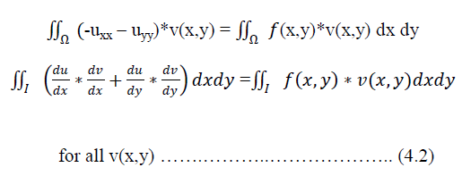 |
| Here we are throwing one derivate of x and y onto v. |
| Now we have found out the weak form and we come to the finite element idea. Finite element idea is to choose the trial functions and write „uâÃâ¬ÃŸ as a linear combination of the trial functions. |
| U = u1ÃâÃâ1(x, y) + u2ÃâÃâ2(x, y) + ………………… unÃâÃân(x, y) |
| In our problem, we will have 13 nodes in the triangle, which is our domain. So we will have 13 trial or basis functions. We will also choose our test functions to be the same as the trial functions. Also we are working on 13 dimensions instead of infinite dimensions. For this finite element subspace or piecewise linear polynomial subspace, we plug the trial functions and the test functions in the weak form (equation 4.2). In this method, we find entries of K matrix one by one. |
| The other method to do this is take the elements one by one. The element will have two trial functions and so we make 2X2 local stiffness matrices. These local stiffness matrices are then combined to produce the global stiffness matrix „KâÃâ¬ÃŸ. This is how the code will be executed in Matlab. |
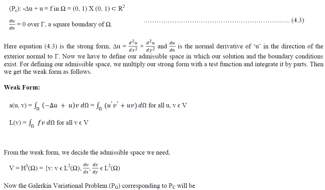
| In earlier example, we showed, how FEM 2D is executed in the computer using a Matlab code. Now letâÃâ¬ÃŸs see, how it is done theoretically. Let us take another problem to understand the concept. |
A.Problem |
 |
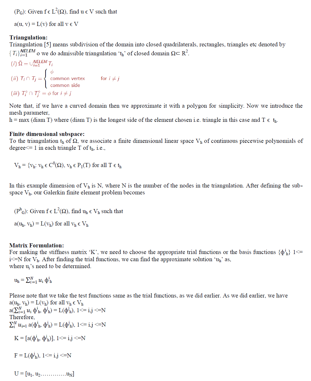 |
| Therefore we got the matrix KU = F where,is the global stiffness matrix K. is the global load vector. is the unknown vector. |
Construction of Basis Function: |
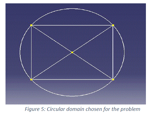
| In this example, say we take the dimension of Vh as 5, i.e. we have 5 nodes in our domain as shown in the figure 5. We have approximated our curved circular boundary with a rectangle and divided into 4 triangles. Accuracy of our approximate solution uh will be very less with this domain. For less error, we should take a higher polygon and divide it into more triangles. |
 |
| To each global node ai (1<= i <=N), we associate a pyramidal function „ÃâÃâi hâÃâ¬ÃŸ as explained before. This pyramidal function has a unit height over the triangles containing the node ai and vanishes over the triangles not containing ai as one of their nodes. This implies, |
| • ÃâÃâi h(ai) = 1, ÃâÃâi h (aj) = 0 for all i ≠ j. |
| • Height of pyramidal function is 1 at ai. |
| • ÃâÃâi h ÃÂõ P1(T) for all T ÃÂõ th. |
| For construction of the global basis function, we need to use barycentric coordinates for a triangle. We define a closed convex hull T by, |
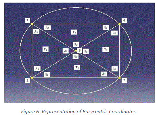 |
| Where λi is the barycentric coordinates of any point x ÃÂõ T and ai are the vertices of a particular triangle chosen. Now any point x, can be represented using the barycentric coordinates. |
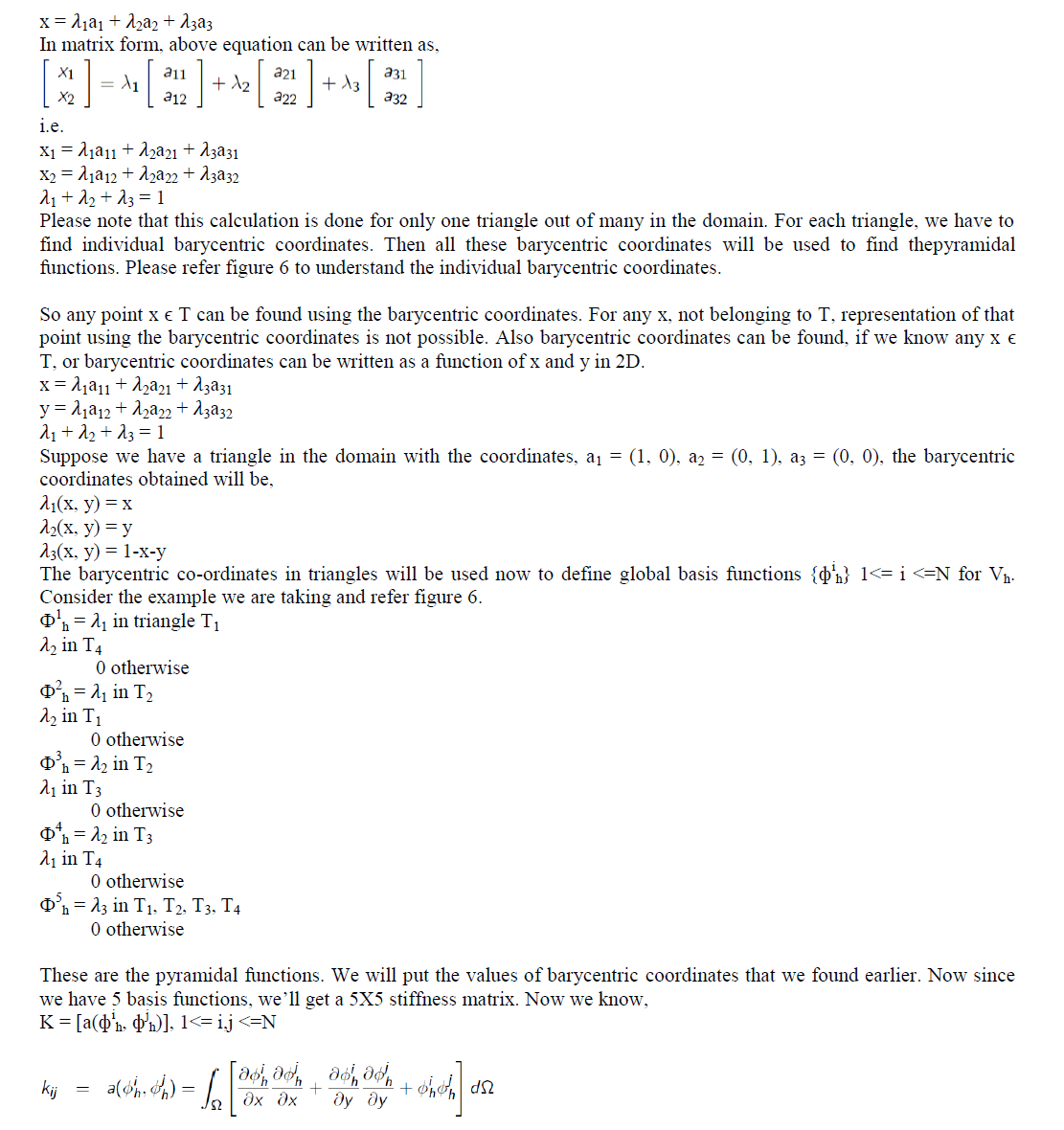 |
| During implementation, we first compute the element stiffness matrices and the element load vectors (here element refers to a triangle in the domain). Then we assemble the element matrices to obtain the global stiffness matrix and the global load vector. |
RESULT AND DISCUSSION |
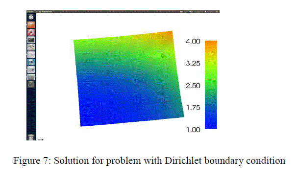
| For the same problem of Poisson equation, solution has been computed with FEniCS [6], |
| • for Dirichlet boundary condition shown in figure 7. |
| • for Dirichlet and Neumann boundary condition shown in figure 8. |
| -Δu = f in Ω with boundary condition |
| u = u0 in dΩ |
 |
| Δu = f in Ω |
| u = 0 on ΓD |
| uâÃâ¬ÃŸ.n = g on ΓN |
| Where |
| Ω = [0, 1] X [0, 1] (a unit square) |
| ΓD = {(0, y) ∪ (1, y) ⊂ dΩ} (Dirichlet boundary condition) |
| ΓN = {(x, 0) ∪ (x, 1) ⊂ dΩ} (Neumann boundary condition) |
| g = sin(2x) (normal derivative) |
| f = 10x2 + 3y3 (source term) |
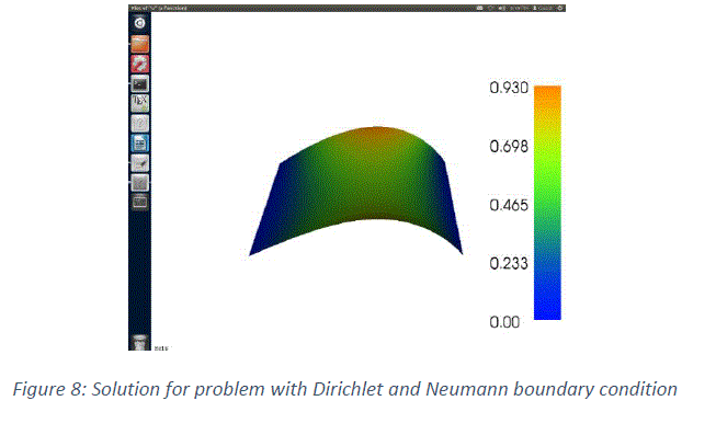 |
| For working with FEniCS, knowledge of python coding is required. Figure 7 and 8 shows the value of „uâÃâ¬ÃŸ at various points in the domain. For obtaining the solution at a particular line or point in the domain, we can use the softwareâÃâ¬ÃŸs like „ParaViewâÃâ¬ÃŸ and „VisitâÃâ¬ÃŸ. PDE computation can also be done by various other softwares like Freefem++ etc. |
CONCLUSION |
| This paper presents the basic understanding of Finite Element Method and the methodology to solve any problem of differential equation. The main idea of Finite Element Method is to choose the appropriate basis functions and then expressing the unknown as combination of the basis functions. Finally a stiffness matrix is generated and solution is obtained. The accuracy of solution increases by using higher order polynomials for the basis function but the calculations become difficult and hence the computation time also increases. Finite Element Method can be executed computationally on Matlab, FEniCS, FreeFem++ etc. |
ACKNOWLEDGEMENT |
| The author is grateful to Prof. Mythily Ramaswamy, Tata Institute of Fundamental Research Centre for Applied Mathematics, Prof. Neela Nataraj, IIT Bombay and Post Doc Saumya Bajpai, for providing continuous support and guidance in understanding of Finite Element Method. |
References |
|