ISSN ONLINE(2319-8753)PRINT(2347-6710)
ISSN ONLINE(2319-8753)PRINT(2347-6710)
Amit L Talli 1, B. B. Kotturshettar 2
|
| Related article at Pubmed, Scholar Google |
Visit for more related articles at International Journal of Innovative Research in Science, Engineering and Technology
The Robot kinematics deals with the position of links which are connected with the help of joints, which gives the position and orientation of every link present in the robot manipulator to place the end-effector to the required target. A kinematic model of the anthropomorphic robot manipulator was developed using multibody dynamic software called MSC. Automated Dynamic Analysis of Mechanical Systems (ADAMS) which represents the human arm. The shoulder joint is considered as spherical joint and elbow joint as a revolute joint. Kinematic equations and Software model is developed to compare and verify the working of the robot manipulator. The Workspace of the robot manipulator was traced to show the maximum and minimum working area of the manipulator. The workspace of the robot manipulator is traced in MSC. ADAMS to show the working region of the manipulator.
Keywords |
| Anthropomorphic, End-effector, Forward Kinematics, MSC. ADAMS, Workspace. |
INTRODUCTION |
| A manipulator can be schematically represented from a mechanical viewpoint as kinematic chain of rigid bodies (links) connected by means of revolute or prismatic joints. One end of the chain is fixed to a base, while an end-effector is attached on the other end [1]. |
| Robot arm kinematics deals with the analytical study of the geometry of motion of a robot arm with respect to a fixed reference coordinate system as a function of time without regard to the forces / moments that cause the motion [2]. Kinematic equation gives the relationship between the joint displacement and the position and orientation of endeffector is determined. Determining the final position & orientation of the end effector depending upon the joint angles is known as forward kinematics and finding the joint angles depending upon the position of end effector is known as inverse kinematics [3]. |
| An end effector is a device that attaches to the wrist of the robot arm and enables the general – purpose robot to perform a specific task. It is sometimes referred to as robotâÃâ¬ÃŸs “hand” [4]. |
| In robotics, end effectors are fixed /attached to the robot arm, which interacts with the surroundings like a human hand having fingers to lift or grab. Gripper is an end effector or tool to grab any object or any tools, which can be used for welding, painting etc. The gripper performs tasks such as picking, grasping or holding by various means for different applications [5]. |
| Workspace refers to the space within which the robot can manipulate its wrist end. Workspace is also referred as working volume of a robot manipulator, which becomes an important indicator to measure the performance of the robot manipulator. The shape and size of the workspace / work volume depends upon the kinematic configurations of the robot manipulator [6]. |
| The MSC. ADAMS software is capable of simulating kinematics and kinetics behaviour of any mechanical system. The dynamic behaviour of a system can be compared with the real models that can be simulated with an acceptable variation in the result [7]. MSC. ADAMS software tool plays very important tool for rapid virtual prototyping which reduces the design failure or feasibility of the design. Real prototype model takes lots of time to test because it needs testing setup and environment. MSC. ADAMS incorporates all the required dynamics virtually which is required for real testing conditions. Various modeling files can be imported in MSC. ADAMS from SolidWorks, Creo, Catia or Solidedge etc. [8]. |
RELATED WORK |
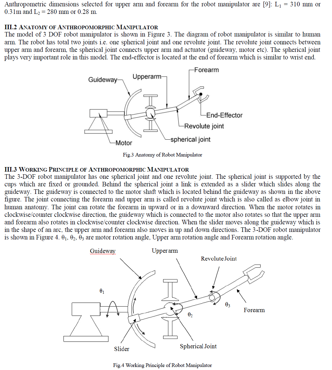
| The robot manipulators are classified depending upon their configuration, such as Cartesian robot, Cylindrical robot, Spherical robot, SCARA robot, Articulated robot, Parallel robot. These robots consist of revolute joint or prismatic joints to meet the desired motion. The revolute and prismatic joints are very simple and are not complicated to use. These joints have one degree of freedom, so that linear motion is achieved in case of prismatic joint and rotary motion is achieved in case of revolute joints. Kinematic analysis, Simulations is performed by using MATLAB simulink or sometimes VRML (Virtual Reality Modeling Language) is used to carry out analysis part. This paper deals with a new robot manipulator, which uses a spherical joint. Spherical joints are very complex in nature due to its number of degrees of freedom. Sometimes it becomes necessary to deactivate at least one degree of freedom to avoid redundancy error. This robot manipulator closely resembles the functions of a human arm. The kinematic equations are developed and verified in MSC. ADAMS by comparing the analytical results and software results. |
METHODOLOGY |
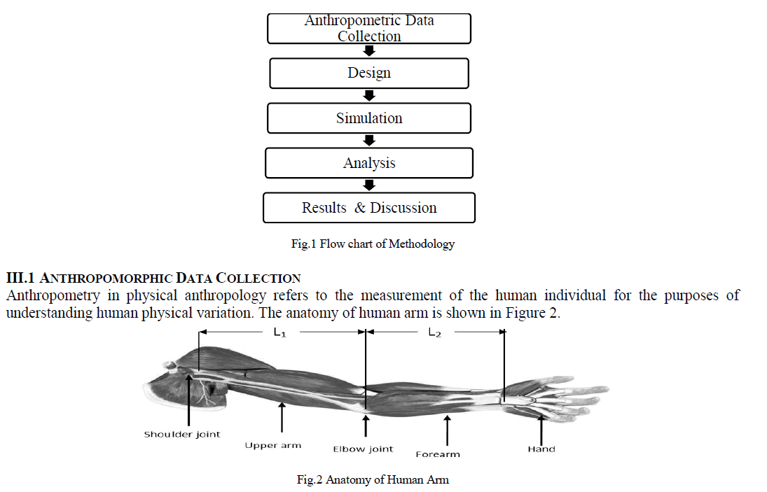
| The block diagram represents the step by step methodology for the kinematic analysis, simulation and workspace tracing robot manipulator is shown in Figure 1. |
 |
 |
 |
 |
 |
| Figure 12 represents the wireframe view of workspace of the manipulator. |
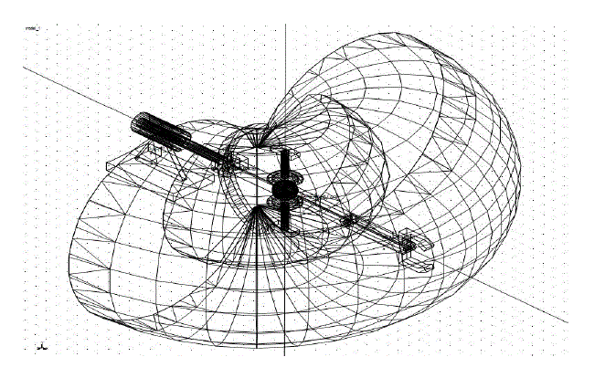 |
| Fig. 12 Wireframe view of workspace of robot manipulator |
CONCLUSION |
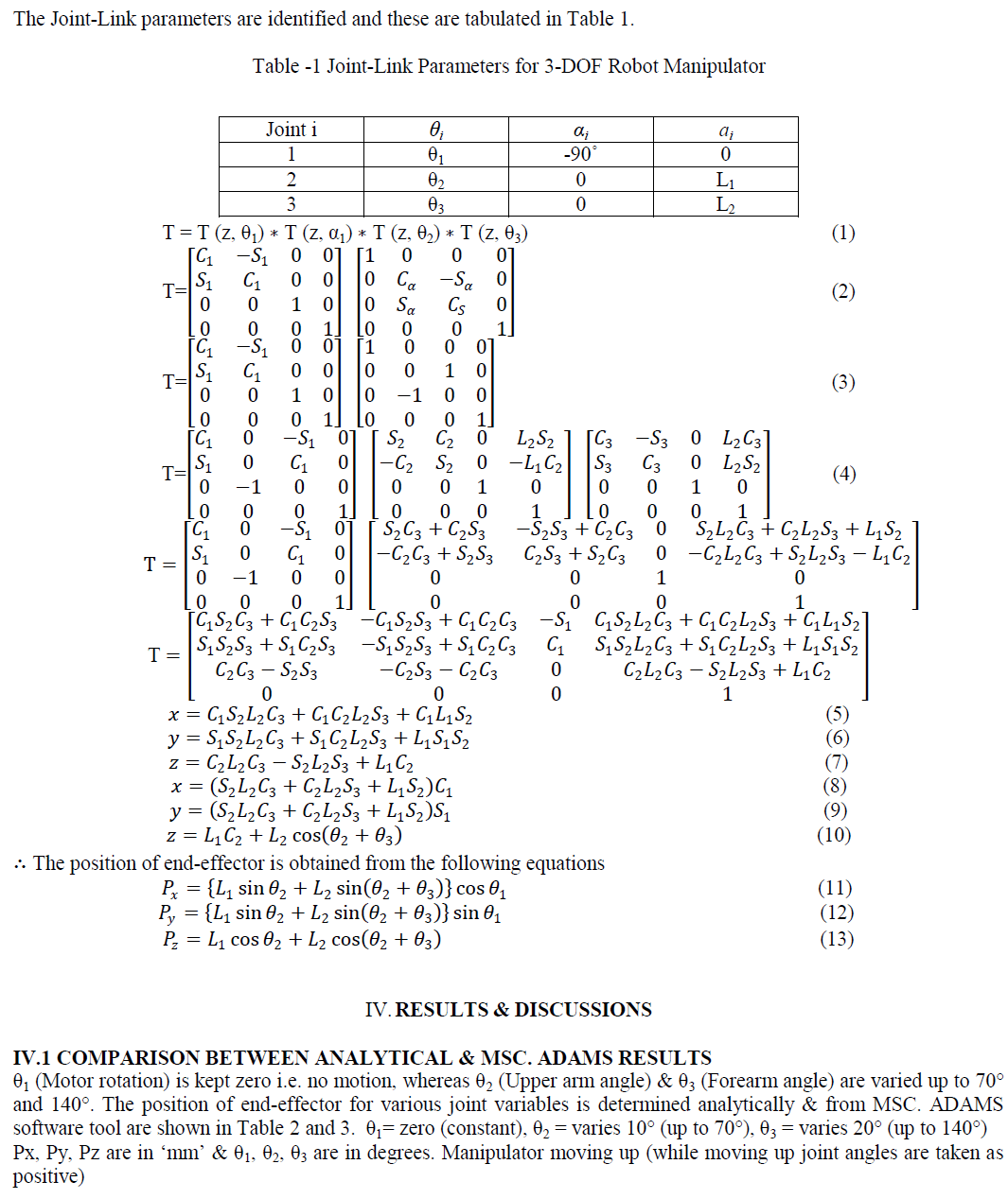
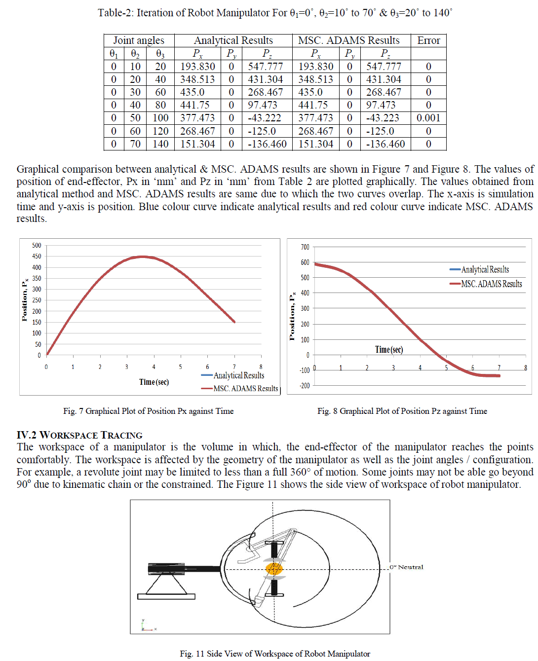
| A complete virtual model of 3 Degrees of Freedom robot manipulator is developed by using anthropometric data. Simulation of the model was performed by using MSC. ADAMS. All desired motions were achieved by using a spherical joint in robot configuration. The results obtained from analytical and MSC. ADAMS are same and validates the developed equations. Workspace profile of the robot manipulator was traced to show the profile of working region of manipulator. The performance and feasibility of the design of robot manipulator can be checked using MSC. ADAMS before going for physical model which is time consuming process. |
References |
|