ISSN ONLINE(2319-8753)PRINT(2347-6710)
ISSN ONLINE(2319-8753)PRINT(2347-6710)
| Faijubhai R.Malek Assistant Professor, Dept of Mechanical Engineering, G.H.Patel College of Engineering and Technology, VallabhVidya Nagar, Gujarat, India |
| Related article at Pubmed, Scholar Google |
Visit for more related articles at International Journal of Innovative Research in Science, Engineering and Technology
In this paper forward kinematic analysis and differential motion analysis of the SCOROT ER V-plus robotic system, which is a 5 d.o.f articulated robotic manipulator, following a specified trajectory is reported. Forward kinematic analysis uses D-H formulation and Differential motion uses Jacobians and determines angular positions and end-effector‟s translational and angular velocity at each via point of its trajectory in the Cartesian space co-ordinates respectively. A trajectory passing through initial point, lift off point, set down point and final point is interpolated in the joint space using cubic splines. The trajectory scheme assumes two more intermediate points on trajectory. Thus, there are five segments of the entire trajectory. A MATLAB source code is developed to obtain all the kinematics parameters and important conclusions are reported from the values obtained.
Keywords |
| Robot, Forward Kinematics, Jacobians, D-H matrix, Trajectory.Introduction. |
Nomenclature |
| Ve is a (6 x 1) vector of end-effectorâÃâ¬ÃŸs translational and angular velocity with respect to fixed base |
| J(q) is a (6 x n) matrix known as a jacobian matrix relative to fixed base |
| q is a (n x 1) vector representing rotational velocities of various joints of robot |
| n is a number showing degrees of freedom of the robot |
| i-1Ti a transformation matrix relating co-ordinate frame {i} with the frame {i-1} |
| 5j jacobian matrix relative to the tool frame {5} |
INTRODUCTION |
| The motion of an industrial robot manipulator is generally specified either in terms of the motion of various joints of the manipulator or that of the end-effectors in the Cartesian space. An accurate direct measurement of end-effectorâÃâ¬ÃŸs position is a complex task and the implementation of a motion control system in Cartesian space can be very difficult. Thus, in practice motion of various joints is converted in the end-effectors motion using forward kinematics. |
| Kinematic parameters are necessary to consider in design and specifications planning, in trajectory planning (programming), and in dynamic computations. A common feature of many of the application problems is the fact that the position of the arm end (end effectors) is frequently described by the user in Cartesian world coordinates [9]. |
| Robot arm kinematics deals with the analytic study of the geometry of motion of a robot arm with respect to a fixed reference co-ordinate system as a function of time without considering the forces and/or moments that cause the motion. Thus, it deals with the analytical description of the spatial displacement of the robot as a function of time, in particular the relations between the joint variable space and the position and orientation of the robotâÃâ¬ÃŸs end-effectors [5]. |
| However, control of link motions is achieved through driving and measuring (for the feedback purposes) of joint coordinates. If the kinematic parameters of the end effectors are expressed in terms of joint parameters, the transformation is called direct or forward kinematics. |
| As a rule, the end-effectors of a robot is programmed to follow a set of desired positions and orientations in the Cartesian space. When it is required to determine how each infinitesimal joint motion affects the infinitesimal motion of the manipulator end-effectors, one has to develop a mapping scheme between the joint motion and the corresponding end-effectorâÃâ¬ÃŸs motion. This mapping is defined by a jacobian. |
| The forward kinematics at the differential level can be represented by a linear system, |
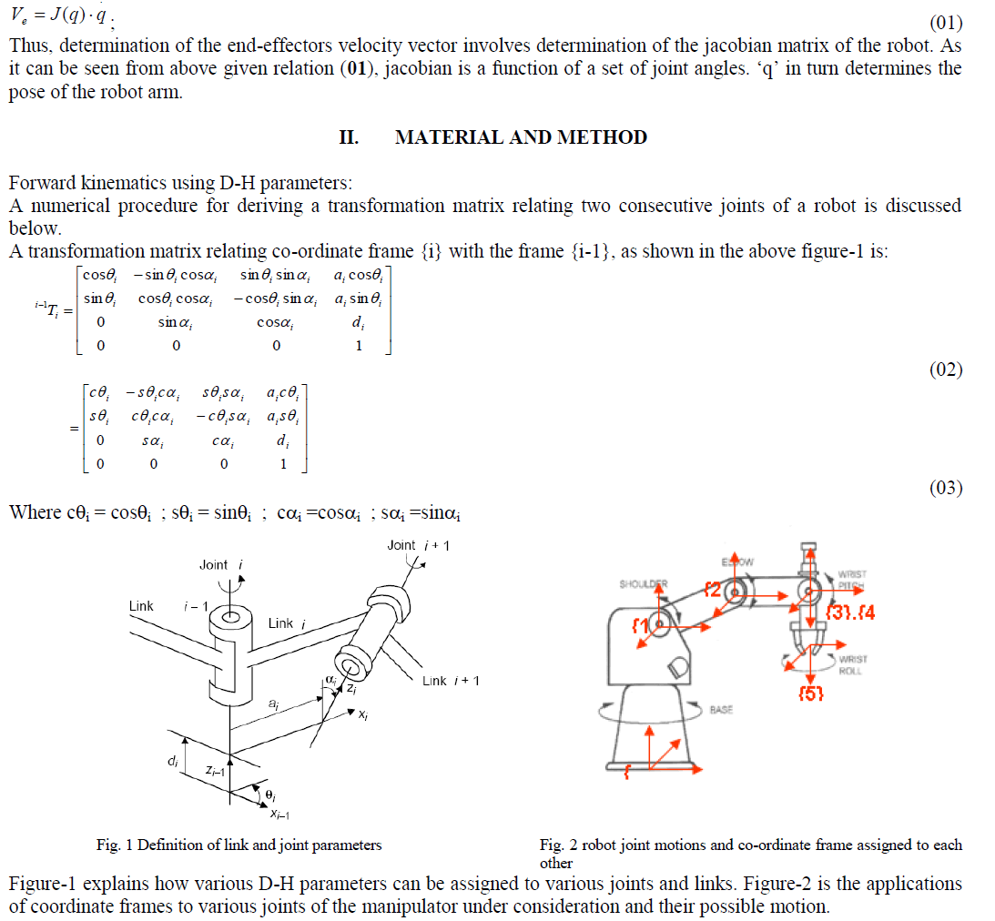 |
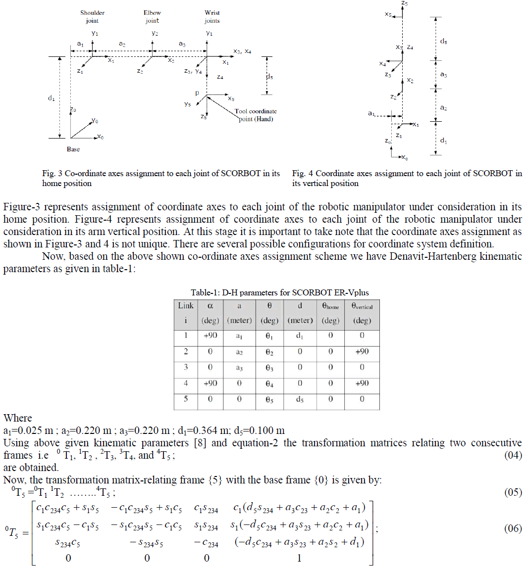 |
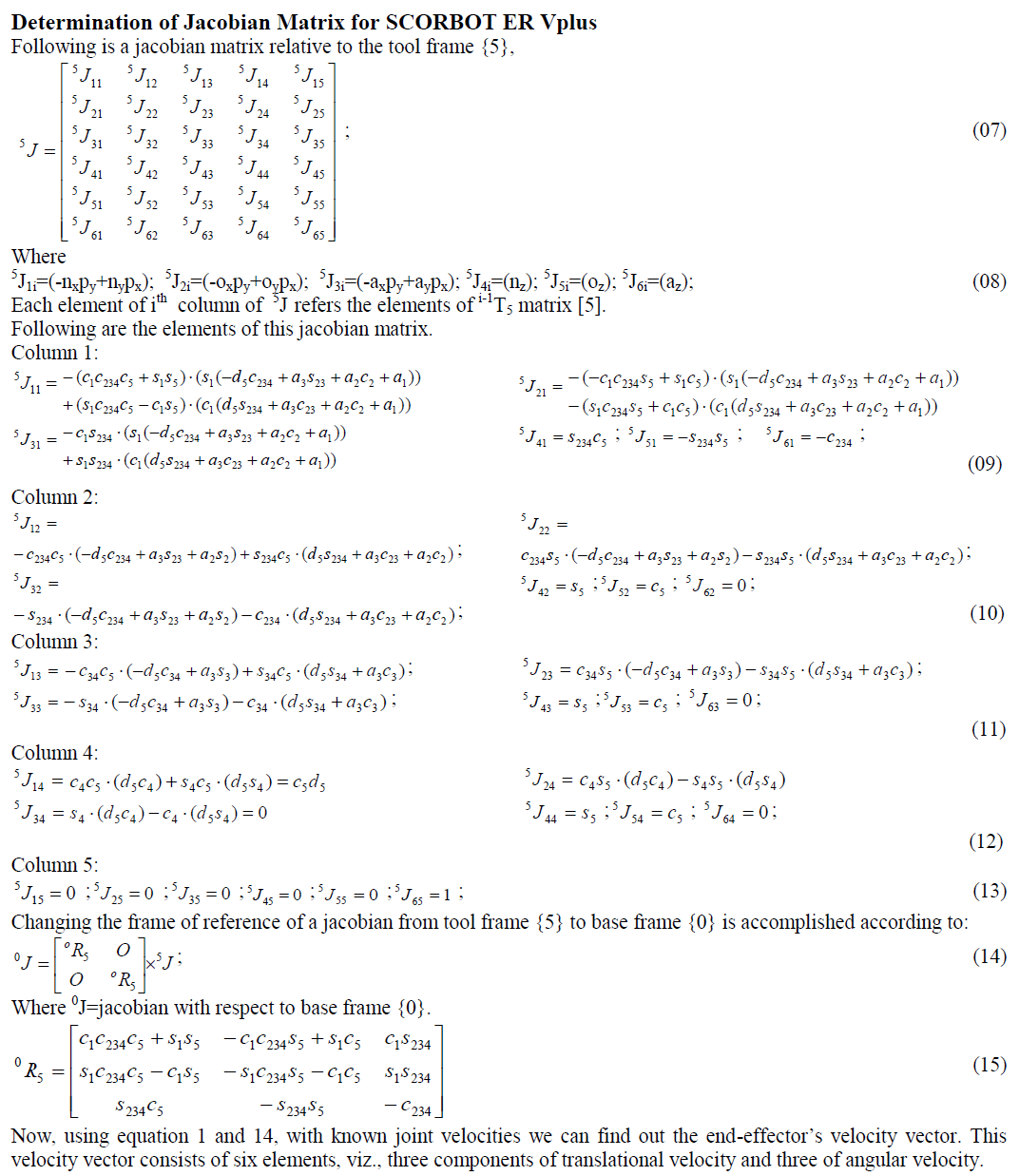 |
APPLICATION |
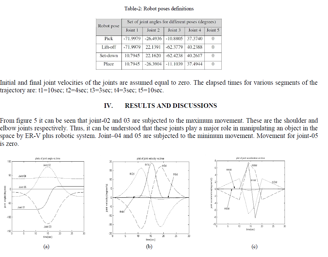
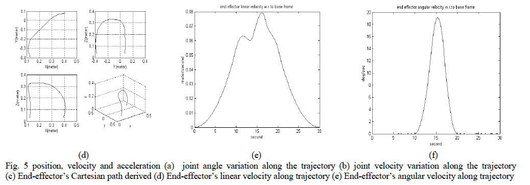
| A numerical example has been developed by referring to a SCORBOT ER-Vplus robot [8] with five revolute joints. The illustrative manipulator task consists of transporting an object from an initial point to a final one. In this task the robot first lift the object from the initial point to an intermediate point called „lift-offâÃâ¬ÃŸ point. From this point it brings it to another intermediate point called „set-downâÃâ¬ÃŸ point, which comes just before the final point. The robot joint positions for these four points are given in table-2. |
| The trajectory passing through these points is interpolated in the joint space using cubic splines. This trajectory scheme assumes two more intermediate points on the trajectory. Thus there are five segments of the entire trajectory. |
 |
 |
CONCLUSIONS |
| This paper presents a general method of carrying out differential motion analysis of a robot manipulator of industrial type, considering its geometric and kinematic parameters. The joint trajectories have been modeled using 5-cubic type of trajectory planning scheme whose coefficients have been determined by using MATLAB codes. Proper trajectory between given initial and final point of the robot hand motion is of considerable importance. The trajectory should give a smooth motion of joints and hence robot hand. Moreover, minimum jerk trajectory is desirable for its similarity to human joints movements and to limit excessive wear on the robot and the excitation of resonance so that the robot life span is long. |
References |
|