This paper presents a space vector pulse width-modulation technique based on fractal approach for multilevel inverters is presented. Here the properties of fractal structure together with the simplicity of fractal arithmetic are exploited to generate the SVPWM. The proposed method does not use any lookup tables for sector identification. The switching space vectors are also directly determined without using any lookup tables. Simulations are carried out using MATLAB/Simulink for a three level inverter. The proposed scheme can be extended to an n-level inverter, and a generalized algorithm is also presented
Keywords |
| Fractals, multilevel inverters, space vector Pulse width-modulation (SVPWM). |
INTRODUCTION |
| Multilevel inverters have received a great deal of attention in recent years. In several papers, numerous topologies
have been introduced and studied extensively for utilities, traction, and drive application . These inverters are suitable
for high-voltage applications because of their ability to synthesize output voltage waveforms with a better harmonic
spectrum and attain higher voltages with a limited maximum device rating[2]. Additionally, the harmonic content of
output waveform decreases significantly as the number of inverter levels increases .The two main techniques of PWM
generation for multilevel inverters are sine-triangle PWM SPWM) and space vector PWM (SVPWM)[3]. SVPWM
involves synthesizing the reference voltage space vector by switching among the three nearest voltage space vectors
SPWM involves the comparison of a reference signal with a number of level shifted carriers to generate the PWM The
two main techniques of PWM generation for multilevel inverters are sine-triangle PWM (SPWM) and space vector
PWM (SVPWM) Multilevel SPWM involves the comparison of a reference signal with a number of level shifted
carriers to generate the PWM signal. SVPWM involves synthesizing the reference voltage space vector by switching
among the three nearest voltage space vectors[4]-[5]. SVPWM is considered a better technique of PWM
implementation, owing to its associated advantages as follows: 1) better fundamental output voltage; 2) better harmonic
performance; and 3) easier implementation in digital signal processor and microcontrollers. |
| The implementation of SVPWM involves the following: 1) identification of the sector in which the tip of the
reference vector lies; 2) determination of the three nearest voltage space vectors; 3) determination of the duration of
each of these switching voltage space vectors; and 4) choosing an optimized switching sequence. |
| The proposed method uses simple arithmetic for determining the sector and does not require lookup tables. The
switching vectors are also directly determined using simple arithmetic and hence do not require lookup tables. All the
redundant states of each switching voltage space vector are also generated automatically without using lookup tables. |
FRACTAL |
| Any basic structure that evolves by dividing itself into structures similar to it is said to have fractal structure. A
fractal is a fragmented geometric shape that can be split into parts, each of which is a reduced-size copy of the whole by
a property called self similarity. It is a powerful tool in computational geometry, and so used in many modern graphics
applications. A fractal is a never ending pattern that repeats itself at different scales. This property is called “Self Similarity”. Fractals are extremely complex, sometimes infinitely complex - meaning you can zoom in and find the
same shapes forever. Amazingly, fractals are extremely simple to make[1]. A fractal is made by repeating a simple
process again and again.certain types of fractals are given below. |
| i. Natural fractals. |
| ii. Geometric fractals. |
| iii. Algebraic fractals. |
| iv. Mathematical fractals. |
SIERPINSKI TRIANGLE |
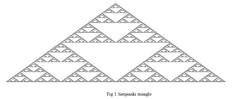
| The basic structure, which is a triangle, is transformed by further dividing itself into smaller triangles. From that
point of view, the switching voltage space vector representation of multilevel inverters has a fractal structure where the
basic structure is a triangle. In a fractal theory the fractal structure with triangle as basic structure that gets divided into
four smaller triangular regions, joined by the midpoints of the sides of the triangle, is called the sierpinski triangle. |
 |
| IV. PROPOSED METHOD OF GENERATION OF PWM FOR MULTILEVEL INVERTERS THROUGH
FRACTALS |
| The implementation of SVPWM involves the following four stages: |
| A) Sector identification; |
| B) Determination of switching voltage space vectors; |
| C) Determination of the duration of each of the determined switching voltage space vectors; and |
| D) Determination of an optimum switching sequence. |
SECTOR IDENTIFICATION AND SWITCHING VECTOR DETERMINATION |
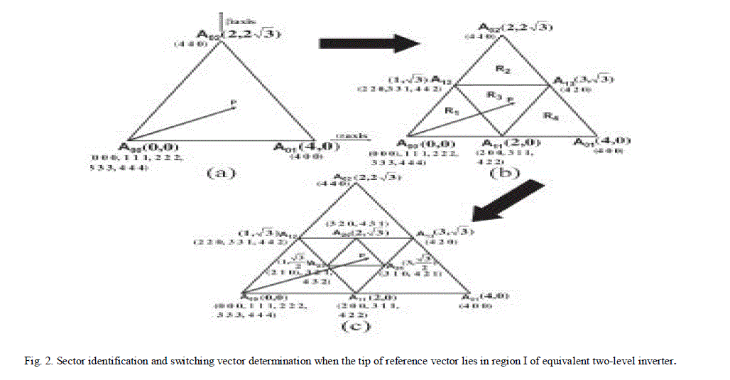
| Sector identification determines the triangle that encloses the tip of the reference space vector. In the proposed
method,sector identification is done using the principle of repeated triangularization. The vertices of triangle (sector)
represent the locations of switching voltage space vectors used to synthesize the reference space vector. From the
instantaneous values of the three reference phase voltages Va, Vb, and Vc, the (α, β) coordinates of the voltage space
vector are determined. The (α, β) components of the space |
 |
 |
| The triangle with centroid closest to tip of reference space vector is ΔA11A12A13. |
| The sector is identified, and the inverter states corresponding to the switching vectors located at the vertices of the
identified sector are also generated simultaneously. vertices of the hexagon forming the periphery are the same as the
vectors of equivalent two-level inverter, having the The coordinates of the centroid of an equilateral triangle can be
determined as the average of coordinates of the three vertices. represented by a vector of length four (Fig. 2). |
 |
SWITCHING VECTOR TIME CALCULATION |
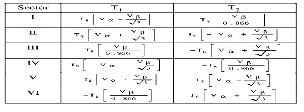
| The next stage in the generation of SVPWM through the proposed method involves determining the duration for
which the voltage space vectors located at the vertices of the identified sector are to be switched. The determination of
the duration of operation of the switching voltage space vectors is simplified by mapping the sector that is identified to
enclose the reference space vector to sector of a two-level inverter . The mapping of the identified sector to a sector of
the two-level inverter is done by mapping one of the three vectors of the identified sector to the actual zero vector in the
voltage space vector representation of the inverter. In this paper, the vector selected to be mapped to the actual zero
vector is referred as virtual zero vector. The vector with minimum value for the sum of magnitudes of α and β
coordinates is chosen to be the virtual zero vector for a particular sector. The sum of magnitudes of α and β coordinates
represents the total offset of the vector from actual zero vector. Therefore, the chosen virtual zero vector is the vector at
minimum offset from zero vector. The duration of the third vector (T0), which is the virtual zero vector, is also
determined. From the determined T0, T1, and T2, the actual inverter leg switching times, designated as Tga, Tgb, and
Tgc, are also determined as in [12]. The Tga, Tgb, and Tgc signals are used to generate the three PWM signals
PWM_A, PWM_B, and PWM_C, respectively. |
 |
OPTIMIZED SWITCHING SEQUENCE SELECTION |
| Once the switching vectors are determined and their respective durations are calculated, then vectors are to be
switched in an optimum sequence such that only one switching occurs when the inverter changes its state. In the space
phasor PWM technique, the optimum switching is achieved by using the redundant states of the zero vector for
alternate switching cycles. In this paper, the optimum switching is achieved by using two redundant switching states of
the respective virtual zero vector in the alternate cycles. For every sector, the switching of the voltage space vectors
starts and ends at the redundant states of the virtual zero vector. Therefore, in this paper, optimum switching sequence
is achieved by adopting a strategy of selecting the switching state of the virtual zero vectors from the available
redundancies. This simple strategy of choosing the switching states from the available redundant states achieves
optimum switching in every sector and hence does not require lookup tables. |
IN THE OVERMODULATION REGION |
| In the over modulation region, also the sector identification, switching vector determination, and determination of the
virtual zero vector for the sector enclosing the reference space vector are done by utilizing the strategy explained
earlier. It may be noted that, during overmodulation, in the case of two-level inverter, zero vector will not be switched
and, in the case of multilevel inverters, the virtual zero vector will not be switched so that the entire sampling period is
shared by only two vectors. This principle is used to detect the overmodulation region, and after mapping to the twolevel
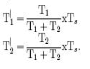
inverter hexagon, T1 and T2 time periods are modified so that Ts = T1 +T2 [6]-[9]. If an overmodulation is detected
(i.e., if T0 < 0), the durations of the nonzero switching vectors are modified from T1 and T2 to T|1 and T|2, respectively,
as |
 |
INVERTER CONFIGURATION |
| The proposed scheme of generating SVPWM for multilevel inverters can be applied to any generalized inverter
configurations like neutral point clamped, H-bridge configuration, capacitor clamped inverters, and open end winding. |
| The inverter configuration is achieved by feeding the induction motor from both winding ends by two two-level
inverters [11]. The inverters I and II switch between the levels zero and Vdc/2, resulting in three voltage levels across the
winding of the motor −Vdc/2, zero, and +Vdc/2. The three voltage levels are represented using the digits 0, 1, and 2. |
ALGORITHM FOR INVERTER LEG SWITCHING TIME CALCULATION FOR AN n-LEVEL
INVERTER |
| 1) Read the instantaneous amplitudes of phase voltages. |
| 2) Determine the coordinates of the instantaneous reference space vector. |
| 3) Normalize the coordinates of the reference space vector through division by VDC/n − 1. |
| 4) Determine the triangular region enclosing the normalized reference space vector for an equivalent two-level inverter. |
| 5) Determine r, which is the number of iterations of steps 6) to 9). Steps 6) to 9) are repeatedly applied on the triangular
region in step 4). r is given in (7). |
| 6) Perform a triangularization on the triangular region identified in step 4). |
| 7) Determine the centroid of each of the four triangles given by (7) and (8). Also determine the triangle with centroid
closest to the normalized reference space vector. |
| 8) If the number of applications of steps 6) to 9) is r, go to step 11); else, go to step 6). |
| 9) The triangle finally determined in step 9) represents the triangle (sector) enclosing the reference space vector. |
| 10) Select the virtual zero vector from the vectors located at the vertices of the identified sector. |
| 11) Subtract the coordinates of the virtual zero vector from the coordinates of the identified sector. |
| 12) Determine the duration of each switching voltage space vector using conventional equations for a twolevel inverter. |
| The duration of zero vector T0 =Ts − (T1 +T2). If T0 < 0, go to step 13); else, go to step 14). |
| 13) T0 < 0 implies overmodulation. T1 and T2 are modified according to (9) and (10). |
| 14) Determine the inverter leg switching times using T1 and T2, and generate the PWM. |
| 15) Go to step 1). |
SIMULATION RESULTS |
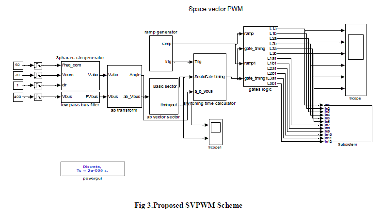
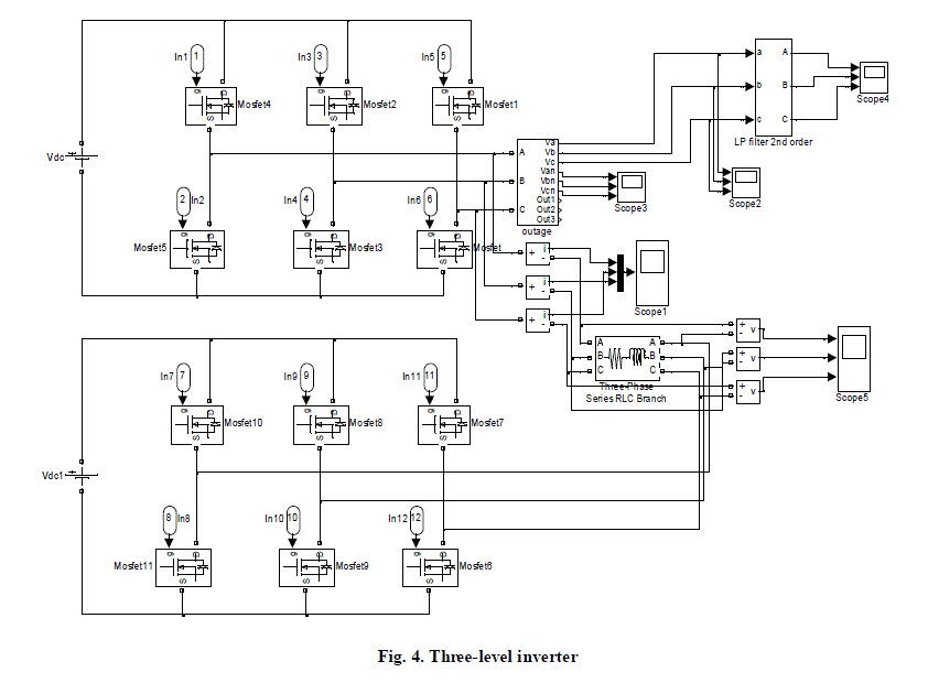
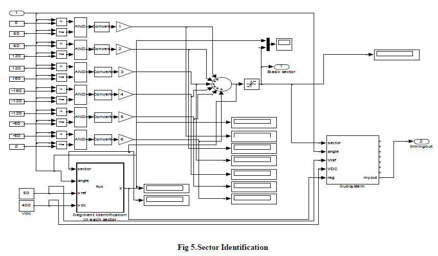
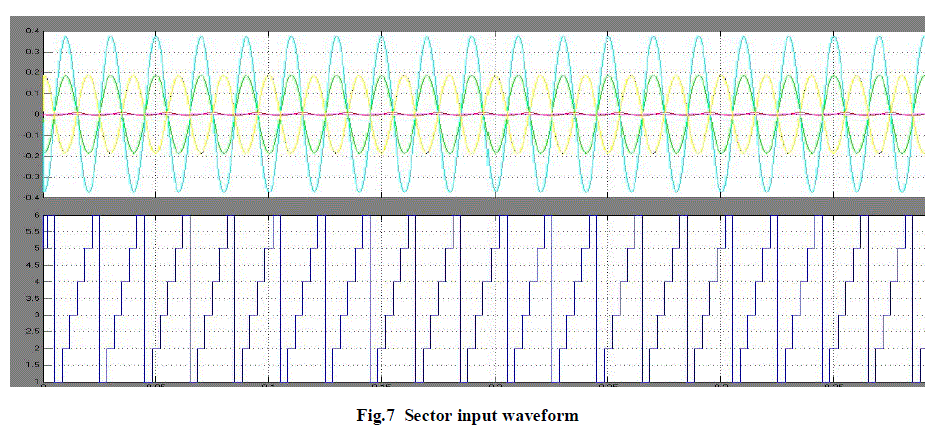
| In this paper, the proposed system was simulated using Simulink and Sim Power Systems Toolbox. The simulation
circuit of the proposed SVPWM scheme is shown in figure 3. The simulation circuit of the three level inverter and the
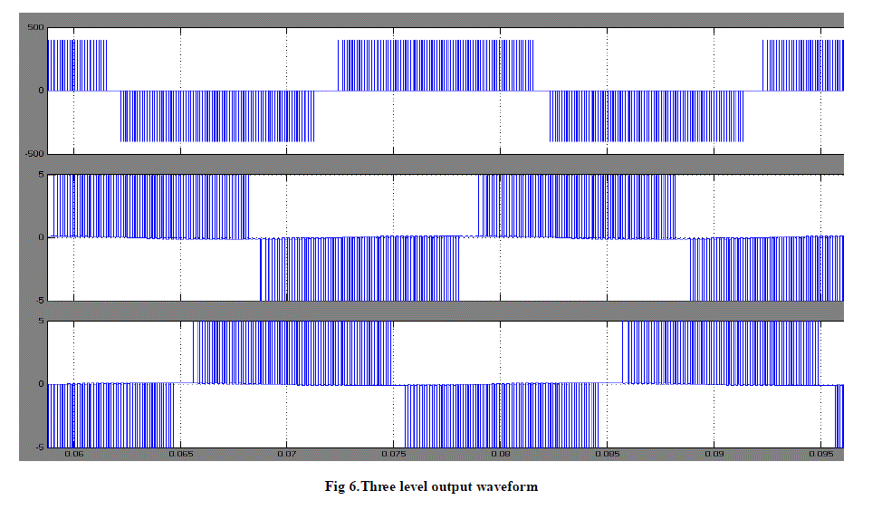
sector identification are shown in figure 4 and 5. The three level inverter output waveform and the sector input
waveform are shown in figure 6 and 7. |
 |
 |
 |
 |
 |
CONCLUSION |
| In this paper, presented a method of generating SVPWM for multilevel inverters using the fractal structure. The
proposed method exploits the features of the fractal representation and the simplicity of fractal arithmetic. The sector
identification algorithm proposed does not need lookup tables, and the inverter switching states corresponding to the
sector are generated simultaneously along with the sector identification. Optimum switching of the vectors is also
achieved without using lookup tables. Simulations are carried out using MATLAB/Simulink. |
References |
- Fractal Based Space Vector PWM for Multilevel InvertersâÃâ¬ÃâA Novel Approach AnishGopinath, Aneesh Mohamed A. S., and M. R. Baiju, Member, IEEE IEEE TRANSACTIONS ON INDUSTRIAL ELECTRONICS, VOL. 56, NO. 4, APRIL 2009
- J. Rodriguez, J.-S. Lai, and F. Z. Peng, âÃâ¬ÃÅMultilevel inverters: A survey of topologies, controls, and applications,âÃâ¬Ã IEEE Trans. Ind. Electron., vol. 49, no. 4, pp. 724âÃâ¬Ãâ738, Aug. 2002.
- W. Yao, H. Hu, and Z. Lu, âÃâ¬ÃÅComparisons of space-vector modulation and carrier based modulation of multilevel inverter,âÃâ¬Ã IEEE Trans. Power Electron., vol. 23, no. 1, pp. 45âÃâ¬Ãâ51, Jan. 2008.
- K. Zhou and D. Wang, âÃâ¬ÃÅRelationship between space-vector modulation and three-phase carrier-based PWM: A comprehensive analysis,âÃâ¬Ã IEEE Trans. Ind. Electron., vol. 49, no. 1, pp. 186âÃâ¬Ãâ196, Feb. 2002.
- G. Carrara, S. G. Gardella, M. Marchesoni, R. Salutari, and G. Sciutto, âÃâ¬ÃÅA new multilevel PWM method: A theoretical analysis,âÃâ¬Ã IEEE Trans. Power Electron., vol. 7, no. 3, pp. 497âÃâ¬Ãâ505, Jul. 1992.
- N. Celanovic and D. Boroyevich, âÃâ¬ÃÅA fast space-vector modulation algorithm for multilevel three-phase converters,âÃâ¬Ã IEEE Trans. Ind. Appl., vol. 37, no. 2, pp. 637âÃâ¬Ãâ641, Mar./Apr. 2001.
- P. F. Seixas, M. A. Severo Mendes, P. D. Donoso-Garcia, and A. M. N. Lima, âÃâ¬ÃÅA space vector PWM method for three-level voltage source inverters,âÃâ¬Ã in Proc. IEEE APEC, 2000, vol. 1, pp. 549âÃâ¬Ãâ555.
|