ISSN ONLINE(2319-8753)PRINT(2347-6710)
ISSN ONLINE(2319-8753)PRINT(2347-6710)
| Dr. Niranjan Murthy1 Associate professor, Department of Mechanical Engg, M.S.Ramaiah Institute of Technology, Bangalore, Karnataka, India |
| Related article at Pubmed, Scholar Google |
Visit for more related articles at International Journal of Innovative Research in Science, Engineering and Technology
The use of impinging liquid jets in electronics thermal management is more attracting because of high heat transfer coefficients are achieved. In the present investigation an experimental study of the cooling capabilities of multiple water jet arrays were presented. For a square array of 49 jets of 0.25 and 0.5 mm diameter and a fixed jet spacing of 3mm were investigated. The arrays impinged on a test surface of 2X2 cm area. The tests were conducted for a flow rate range of 1300 to 2400ml/min for 0.5mm diameter jet and 800 to 1400 for 0.25mm diameter jet. The jet diameter of 0.25mm is found to be more effective causing higher values of heat transfer co-efficient, even with lower values flow rates. With jet diameter of 0.50mm, the effect of flow rate on the heat transfer co-efficient is reduced.
Keywords |
| Multiple jet impingement, Heat transfer enhancement |
INTRODUCTION |
| The current trend of miniaturizing electronic components associated with increase in speed and transistor density leads to increases in the high surface heat flux levels. If the thermal management has not taken care properly then it adversely affect its performance, reliability and lifespan. Jet impingement cooling is widely used in engineering applications because of high heat transfer performances. Jet cooling is used in various geometrical configurations implementing either in a single jet or multiple jets. |
II RELATED WORK |
| Womac [1] et al investigated both free-surface and confined-submerged jet impingement heat transfer using FC-77 and water as coolants. Arrays of 3X3 and 2X2 circular jets were tested for jet diameters of 1.02mm and 0.513mm for different pitches .It was found that the heat transfer to the free surface jet is independent of the jet to target space in the range of 5≤ H/dn≤ 10. It was observed that for a constant flow rate heat transfer increases with decrease in values of N and dn . When the values of N ,flow rate and dn were held constant, the heat transfer was found to increase with vaues of jet to jet spacing. In the experiments conducted for the confined liquid jet arrays noticed that heat transfer coefficient was insensitive to jet to target spacing in the range of 2≤ H/dn≤ 4 because the target space is within the potential core of the issuing jets. Pan and webb [10] have examined closely the effect of jet to jet spacing. The local heat transfer distribution was investigated with water as the test fluid for a 9 jet inline arrays and a staggered array over a various jet to jet spacing between 2≤ S/dn≤ 8. The stagnation point heat transfer was found to be independent of the jet to target spacing. Fabbri and Dhir [11] to be one of the first to consider both heat transfer and jet arrays and the associated pressure drop across the jet nozzle plate. The research investigated free surface micro jet arrays of water and FC40 within a Reynolds number range of 73 to 3813, jet diameter o range of 65μm to250μm. It was found that the average heat transfer coefficient was increased with the increase in Reynolds number and Prandtl number as well as decrease in S/dn.The minimum pumping power requirement for a given required heat dissipation was found to be dependent upon the jet diameter and interjet spacing.It was also noted that heat transfer to the micro jet arrays was considerably larger than for miniature and mesoscale for identical flow rates. |
III EXPERIMENTAL APPARATUS AND TEST PROCEDURE |
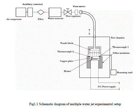
| The test apparatus is shown schematically as shown in Fig1.1. The apparatus is designed and fabricated to carry out tests using different types of nozzles. The arrangement consists of air compressor, fluid delivery system, heater assembly, jet nozzle head and the test stand. The fluid delivery system consists of a water reservoir, auxiliary reservoir, flow control valves, pressure gauge, filter and piping systems. The auxiliary reservoir acts as a buffer and smooth out flow fluctuations to provide steady flow at the nozzle. The heater assembly consists of hot plate, heating element, thermocouples, variable voltage transformer and a control - display system. The hot plate is of 20mm x 20mmsize and thickness 1mm. The hot plate was mounted on the heating element. The heating element is a Nichrome wire of 16 gauge, 2 ohm, and wattage capacity of 1kW. The power to the heater is controlled using the variable voltage transformer. Two thermocouples were mounted underneath the hot plate on the centre line and insulated with ceramic insulation. These thermocouples also provide indication of surface temperature uniformity on the plate. The complete heater assembly is mounted and insulated using a Teflon jacket. The leads from the thermocouples are connected to the control display system. The functions of the control and display system includes (a) To vary the heat input to the hot plate using the transformer (b) To display the hot plate surface temperatures, input voltage and current using digital temperature indicator, voltmeter and ammeter and (c )Limit the maximum surface temperature and automatically cut off the power supply when the hot plate temperature exceeds the set value. The Jet nozzle head is made of stainless steel and it consists of the nozzle chamber and nozzle plate. The nozzle chamber is connected to the reservoir through a connecting tube. The nozzle plate is made of 3mm thick stainless steel plate. The nozzle plate is designed to cover the nozzle chamber making it a single leak proof unit. Two nozzle plates having 0.25mm and 0.5mm diameter holes were used. The holes are laser drilled and arranged in a square array of 7X7 with a pitch distance of 3mm between the holes. The distance between the nozzle plate and the hot plate surface is maintained at 10mm . The test stand consists of a base tray, mounting plate, hot plate, movable nozzle plate and a top plate held together by vertical support rods. The nozzle head is attached to the nozzle plate which could be moved vertically. A calibrated screw thread assembly is provided along with a circular scale on the top plate. The nozzle plate can be fixed at the desired height by accurate positioning of the calibrated screw head. The hot plate surface is cleaned to remove residual adhesive stains and dust on the surface before starting the experiment. Compressed air is passed through the tube connecting the reservoir and the nozzle head to remove any dust particles which could block the nozzle. The filter is installed in the flow line prior to the auxiliary reservoir. The flow rate, power input and distance between nozzle exit and test hot plate were varied during the experiments. The hot plate is allowed to reach a steady state before acquisition of test data on flow rate, power dissipation and temperatures from thermocouples. Experiments were conducted by positioning the jets and the hot plate in both horizontal and vertical positions. Before starting the experiments the test plate surface was cleaned to remove the dust and residual adhesive stains on the surface. Compressed air is passed through the tube connecting the nozzle block and the reservoir to remove any dust particles in the nozzle block. Repeatability tests were conducted in order to check the quality of the experimental data. |
 |
IV DATA ACQUISITION |
| The test plate was allowed to reach a steady state. The test data on air/water flow rate, velocity, power dissipation and temperatures was acquired. Prior to the recording of the heat transfer data for analysis, experiment was conducted to obtain the time required to reach the steady state. It was found that the average test plate temperature was within 0.10C of its steady state value within 10 minutes of required power to the test plate. Test surface temperature measurements were recorded using resistive temperature sensors which are mounted underneath of a test surface. The fluid inlet temperature is recorded using a 1.5mm diameter type T thermocouple. The thermocouples were calibrated prior to installation and measurements were compared. The wattmeter was used to measure the heat flux input to the test plate. The flow rate of water was measured using a flow meter and also checked by direct measurements during the multiple water jet experiments. Venturi meter was used to measure the air flow rate in the case of multiple air jet experiments. The U-tube water manometer is connected to the inlet and throat of the venturimeter to measure the pressure drop between these two points and hence the volumetric flow rate. |
V DATA REDUCTION |
| Heat flux was calculated from the electrical power supplied to the heated test surface. Heat flux is determined using the following relation: q = P/A. The heat transfer coefficient [h] is calculated from the heat flux and to the temperature difference between fluid inlet and test plate surface temperature (Δt). h = q/Δt . |
VI NOMENCLATURE |
| A Hot plate surface area (cm2) |
| d Nozzle diameter (mm) |
| h Heat transfer coefficient (W/cm2C) ( q / (Tc -Tw) ) P Total heat transfer (W) q Heat flux (W/cm2) (P/A ) Q Total flow rate (ml/min) Tb Bulk fluid temperature (0C) Tc Chip surface temperature (0C) Tw Inlet water temperature (0C) z Nozzle height from chip surface (mm) ΔT (Tc -Tw ) (0 C) |
VII RESULTS AND DISCUSSIONS |
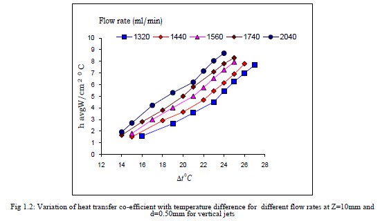
| When continuous liquid jets are employed, the liquid film covering the surface is continuous and the heat is removed mainly by convection. Figs 1.2 and 1.3 shows the variation of heat transfer co-efficient plotted against the temperature difference between the test surface and water at inlet (Δt 0C) for different flow rates for d=0.5mm and jet exit to test plate surface distances (Z). For a given value of (Δt), the heat transfer co-efficient increases with the increase in flow rate. It should be noted that the heat flux is also increasing with the variation of flow rate at the constant temperature difference (Δt). |
 |
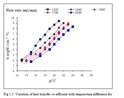 |
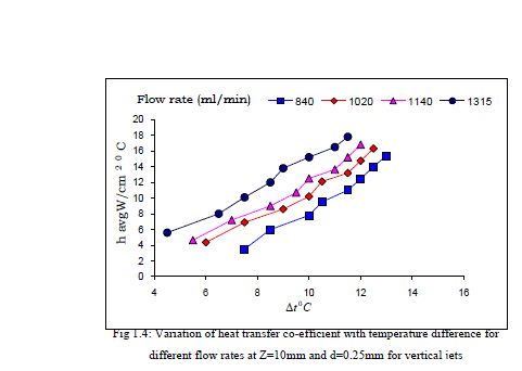
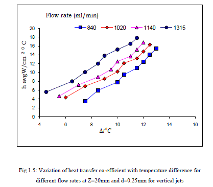
| Thus, the observed increase in heat transfer co-efficient is due to the combined effect of the heat flux and the flow rate. The variation of heat transfer co-efficient with (Δt) for d=0.25mm is shown in Figs 1.4 and 1.5. |
 |
 |
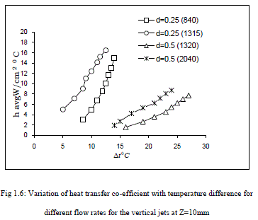 |
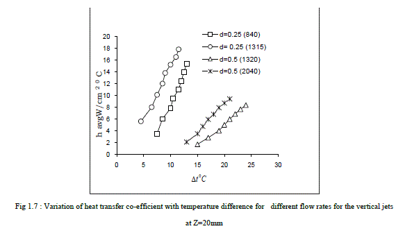
| The (Δt) values are within 4 to 150C for a flow rate range of 840 to 1315 (ml/min) for d=0.25mm. The heat transfer coefficient increases with increase in flow rate. Higher values of heat transfer coefficients are due to the higher jet velocity with increased flow rate. Figs 1.6 and 1.7 show the significant effect of jet diameter on the heat transfer coefficient. Larger shift in the (h) versus (ΔT) curves can be easily noticed due to the change in the jet diameter. The jet diameter of 0.25mm is found to be more effective causing higher values of heat transfer co-efficient, even with lower values flow rates. With jet diameter of 0.50mm, the effect of flow rate on the heat transfer co-efficient is reduced. Similar variations of the heat transfer coefficient with (ΔT) have been observed in the range of test parameters, also for the horizontal positioning of the jets for both the cases of d=0.25 and 0.5mm. Investigations of Jiang,S also reveal that it is better to use a larger number of smaller jets than a single large jet to enhance the heat transfer coefficient. |
 |
VIII CONCLUSION |
| Experimental investigations were carried out to study the cooling capabilities of impinging multiple water jet arrays on a simulated electronic component of size 2x2 cm area. Heat flux is varied from 25 to 200 W/cm2, and the values are typical for the requirement of cooling high power electronic components. Heat was dissipated using 0.5 and 0.25mm diameter jets arranged in a 7x7 array with a jet spacing of 3mm. The difference in temperature between the fluid inlet and test plate is within 300C for water jets and within 700C for air jet experiments. The jet diameter of 0.25mm is found to be more effective causing higher values of heat transfer co-efficient. |
References |
|