ISSN ONLINE(2278-8875) PRINT (2320-3765)
ISSN ONLINE(2278-8875) PRINT (2320-3765)
Bhanu Priya K.1 and Dr. Rama Rao P.V.V2
|
| Related article at Pubmed, Scholar Google |
Visit for more related articles at International Journal of Advanced Research in Electrical, Electronics and Instrumentation Engineering
More-Electric Aircraft (MEA) underlines the utilization of the electrical power to power the nonpropulsive aircraft systems. The aircraft electric actuator (AEA) is an emerging aerospace technology that aims at replacing hydraulic systems with self-contained actuators operated solely by electrical power. This is one of the most important techniques of electric loads of the future more electric aircraft. However, the MEA put some challenge on the aircraft electrical system either in the amount of the required power or the processing and management of this power. In this paper, a novel fuzzy rule based dc-bus voltage switched control method of three-phase voltage source pulse widthmodulated rectifiers (VSRs), implemented to solve the problem of flexible voltage regulating under dynamic loads, is proposed under a nonlinear control in rotating synchronous coordinates d−q. Several linear controllers are designed on different operating points of the VSR, and fuzzy controller is implemented on the VSR system according to certain switching law. The stability of the proposed control approach is guaranteed based on the fuzzy based controller. Simulation and experimental results show that the desired control performance is obtained in the voltage regulating of a VSR with wide-range rapidly varying load. Compared with the classical PI controller fuzzy controller is proved to have less effective under a wide range rapidly varying active load.
Keywords |
| More Electric Aircraft, Power Electronics, Fuzzy Controller, Load Control. |
INTRODUCTION |
| Recently, the aircraft industry has achieved a tremendous progress either in civil or military sectors, for example some currently commercial airliners operate with weights over 300 000 kg and have the ability to fly up to 16 000km in non-stop journey at speed of 1000 km/h. The non-propulsive aircrafts systems are typically driven by a combination of different secondary power types such as hydraulic, pneumatic, electrical and mechanical power. THREE-PHASE voltage source pulse width-modulated (PWM) rectifiers (VSRs) possess many attractive features, such as high power factor, nearly sinusoidal input current, and bidirectional power flow ability [1], [2],[3]. VSRs are increasingly utilized as substitutes for traditional diode rectifiers and phase controlled rectifiers although they are widely used and studied in many industrial applications. |
| The recent breakthroughs in the field of power electronic systems, fault-tolerant electric machines, electrohydrostatic actuators, electromechanical actuators, and fault-tolerant electrical power systems have renewed the interest in the rapidly varying active loads. Nowadays, seldom applications have appeared in the aviation industry. As more electric aircraft (MEA) becoming the main trend for future aircrafts, there exists a sharp increase of electric loads in the aircraft power system [4]. The aircraft electric actuator is one of the most important loads of the future MEA and all electric aircraft power grid [5]. It is a position-servo system that shoulders the task of driving the aircraft control surfaces. Unlike the general electric loads, the aircraft actuators behave as constant power loads (CPLs). In addition, during an action process of an aircraft actuator, the input power would vary rapidly within a wide range. These load characteristics bring significant challenges to the power source. The advanced PWM rectifiers play an important role in these aspects, due to more and more attention paid to the power quality and energy efficiency of the aircraft power grid. Therefore, a further investigation on the VSRs is quite important for the aviation industry, especially under an electric actuator load. |
| Extensive studies on the control of VSRs for desired performances have been reported in the past decades [6]. The classical voltage-oriented control in rotating coordinates, which is a linear design method, becomes a standard solution in industrial applications. However, with a linear controller, both the stability and the performance of a VSR cannot be guaranteed under a wide-range rapidly varying load [7]. Nonlinear control strategies have been extensively studied in the last few years, e.g., feedback linearization strategy and passivity based control methodology [8]. These proposed nonlinear design strategies present large complexity, so it is quite necessary to develop a control method that achieves system stability, desired performance, and simultaneously, easy to design. |
| The current generator technology employed on most commercial and military aircraft is the three-stage wound field synchronous generator. This machine is highly reliable and inherently safe, as the field excitation can be removed, which de-energizes the machine. Therefore, the rating of the three-stage synchronous generator has increased over the years reaching to 150KVA on the Airbus A380. However, the anticipated increased electrical power generation requirements on the MEA suggests that the high power generators may be attached directly to the engine, mounted on the engine shaft and used for the engine start in Integral Starter/Generator (IS/G) scheme. The harsh operating conditions and the high ambient temperatures push most commonly materials close or beyond their limits, therefore innovations in materials, processes and thermal management systems are required. |
| Focusing on wide-range rapidly varying characteristic of the load and the background of industrial application, this paper proposed a switched control strategy for the VSR based on the concept of switched system. Several linear controllers are designed for different operating points of the VSR, and certain controllers are selected according to the load resistance value. |
CHARACTERISTICS OF THE ELECTRIC ACTUATOR LOAD |
| A. Dynamic Nature of the Electric Actuator Load |
| The aircraft electric actuators that drive the movements of control surfaces of an aircraft are rapid position control systems. The actuator load demands a short term, high peak power with a fairly low steady state or background loading of less than 10% of the peak requirement. This obviously depends on the particular application, and it is usually called the dynamic load of the aircraft power grid. |
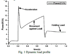 |
| Fig. 1 illustrates the dynamic nature of an electric actuator load as it moves a surface from rest at one position to rest at another position. There are three basic parts to the load cycle [9]. |
| 1. Input of power to accelerate the motor and inertia of the load. |
| 2. Surface moving against the load (motor delivering speed and torque). |
| 3. Surface holding the load (motor delivering torque but no speed). |
| B. Electric Power Processing in MEA |
| There are many occasions within the aircraft electrical system where it is required to convert the electrical power from one level/form to another level/form. Thus the aircraft electrical system has plenty of power electronic circuits such as AC/DC, DC/DC, DC/AC and matrix converters. The general requirements, which these circuits should satisfy, are: |
| 1. The system should have light weight and small size. |
| 2. The system should be fault-tolerant, which implies its ability to continue functioning under abnormal conditions without much loss in the output power or degradation of the performance. |
| 3. The system should be efficient and have the ability for operation in harsh conditions such as high temperature and low maintenance. |
C. Power Distribution and Management System of the Electric Actuator Load |
| The aircraft power system usually consists of a combination of 115V 400Hz AC for large loads and 28V DC for avionics, flight control and battery-driven vital services. However, adopting the new generation options as VF requires using power electronics to convert all the motor/generator outputs into a single high-Voltage DC Distribution system. The value of the system voltage is suggested to be 270, 350 or 540V. Using a high value for the distribution system has the advantages of reducing the weight, the size and the losses, while increasing the levels of the transmitted power. The exact value, however, is determined by a number of factors such as, the capabilities of DC switchgear, the availability of the components and the risk of corona discharge at high altitude and reduced pressure [10]. |
MODELING OF PWM CONVERTERS |
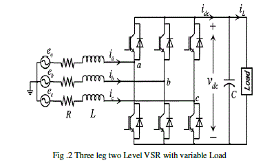 |
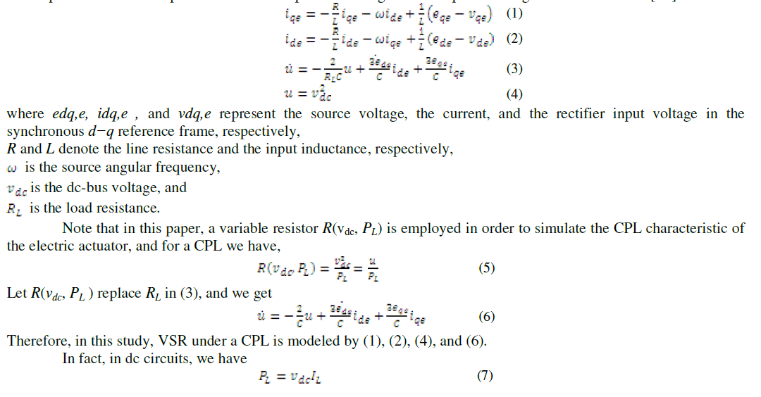
| A power circuit of the three-phase VSR is shown in Fig. 2. It is usually assumed that a resistive load RL is connected to the output terminal. An improved linear state-space modeling of a three-phase voltage source rectifier is [11] |
 |
 |
SWITCHED CONTROL OF VSR’S |
| In this section, a novel switched control method for three phase VSRs will be presented. The switched control method aims at well regulation of the dc-bus voltage of VSRs under a wide-range rapidly varying load. |
| A. Current Controller using classical PI controller |
 |
| B. Space vector Pulse width modulation (SVPWM) Controller |
| Pulse Width Modulation variable speed drives are increasingly applied in many new industrial applications that require superior performance. Recently, developments in power electronics and semiconductor technology have lead improvements in power electronic systems. Hence, different circuit configurations namely multilevel inverters have become popular and considerable interest by researcher are given on them. Variable voltage and frequency supply to a.c drives is invariably obtained from a three-phase voltage source inverter. A number of Pulse width modulation (PWM) schemes are used to obtain variable voltage and frequency supply. The most widely used PWM schemes for three-phase voltage source inverters are carrier-based sinusoidal PWM and space vector PWM (SVPWM). There is an increasing trend of using space vector PWM (SVPWM) because of their easier digital realization and better dc bus utilization. This project focuses on step by step development SVPWM implemented on an Induction motor. |
| The model of a three-phase a voltage source inverter is discussed based on space vector theory. Simulation results are obtained using MATLAB/Simulink environment for effectiveness of the study. |
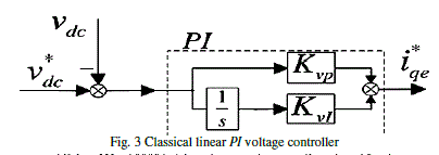
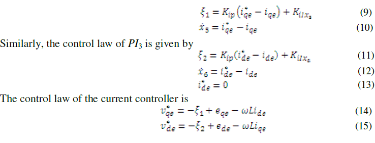
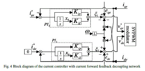
| The current controller that consists of two PI controllers (PI2 and PI3 ) is depicted in Fig. 4. In this control scheme, the cross-coupling terms of ωLide and ωLiqe in (1) and (2) are compensated by feed forward at the last stage of the controller. In consequence, the q-axis current of iqe that is the active current can be controlled independently on ide and u (or ), so can the reactive current ide . The variables of are the reference value of ide and iqe . For unit power factor when rectifying, is zero and is set by the outer voltage controller. Let the variables x5 and ξ1 denote the output of the integrator of PI2 and the output of PI2 , respectively, the control law of PI2 is |
 |
 |
SIMULATION RESULTS |
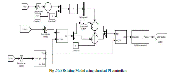
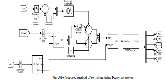
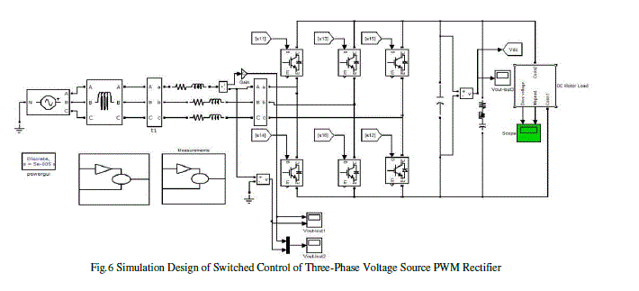
| The rectifier system specified in Section V is modeled in MATLAB/simulink with the aircraft electric actuator load shown in Fig. 1. For the purpose of comparison, simulations are performed for the proposed switched control scheme and the classical linear PI control scheme (the second dc-voltage control method in [12] shown in fig. 5 (a) & (b). |
 |
 |
 |
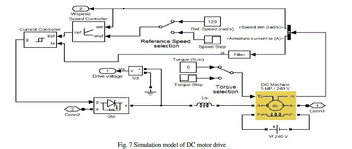 |
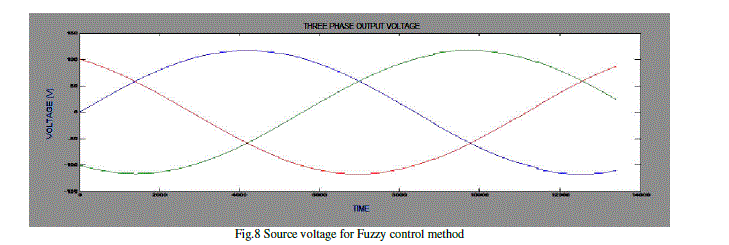
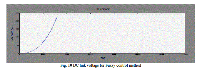
| Fig. 6 shows the response of the proposed switched controller. It can be seen that a balanced and optimized dcbus response, which has an acceptable small ripple, little oscillations during the dynamic process, and a negligible small overshoot in power-up situations, is achieved. |
 |
 |
 |
CONCLUSION |
| Replacing the conventional non-propulsive aircraft power, mechanical, hydraulic and pneumatic with single electric power is known as MEA, and considered as the future trendsetter. The MEA improves the aircraft reliability, affordability, fuel consumption. Moreover, MEA reduces cost of ownership, operation and maintenance cost. However, the implementation of MEA requires innovation in the areas of power generation, distribution and management. Embedding the electrical generator into the aero-engine is considered to be key issue in generating the large amounts of power, as it removes the cumbersome matching gearbox. |
| In this paper, a new switched control method is introduced to control the VSR. The proposed switched voltage control approach can be effectively used as a replacement for classical PI controller could provide a simple, effective way to overcome the problem of wide-range load regulation. Several linear controllers are designed according to the derived switched voltage controller for the VSR at different operating points and a certain controller is selected by the apparent load resistance value. To achieve better responses, one can increase the number of sub controllers of the switched regulator reasonably. Based on the concept of switched system, the stability of the proposed control scheme can be attained. Simulation and experimental results of a switched controlled VSR with an electric actuator load show that the presented switched control method has a desirable capacity of regulating dc-bus voltage with such wide-range rapidly varying dynamic load. |
ACKNOWLEDGEMENTS |
| We thank our Management, Principal and staff of the college for giving their valuable suggestions and extensive support to carry out this work and publishing this paper. |
References |
|