ISSN ONLINE(2278-8875) PRINT (2320-3765)
ISSN ONLINE(2278-8875) PRINT (2320-3765)
VENKATESH TADIVALASA1 and CH.SANDHYA2
|
| Related article at Pubmed, Scholar Google |
Visit for more related articles at International Journal of Advanced Research in Electrical, Electronics and Instrumentation Engineering
This paper presents the optimization and coordination of the conventional FACTs device (i.e. Unified Power Flow Controller) damping controller in multi-machine power system. The design of this controller is based on time-domain analysis and implemented by using other conventional controllers (PSS & FUZZY) to damp low frequency electromechanical (iner-area) power oscillations. The detailed design procedure of UPFC controller is first addressed. Firstly, the parameters of unified power flow controller are optimized, and then a PSS & Hybrid Fuzzy logic controller for the coordination with Facts devices is presented. Digital simulations are then carried out to verify the feasibility of the proposed control scheme. The simulation done on the IEEE multi-machine power system with 12-bus and results are shows that the proposed damping method is implementable and UPFC based Fuzzy system providing the satisfactory performance than other conventional controllers and meeting the design objectives.
Keywords |
| Power Flow Controller, PSS, Hybrid Fuzzy Logic, Damping and Stability. |
INTRODUCTION |
| With more important to control the power flow along the transmission line and thus to meet the needs of power transfer. Different types of FACTS devices like static compensator (STATCOM), unified power flow controller (UPFC), thyristor controlled static compensator (TCSC), etc. have been studied to show their effectiveness in improving voltage and angle stability and reducing electromechanical oscillations in interconnected power systems. The several FACTS devices studied for power system stabilization, STATCOM and UPFC provide the most significant performance in damping out low frequency multimodal oscillations in interconnected power systems. As utilities increase power exchanges over a fixed network, interarea oscillations are more likely to happen, even under nominal operating conditions. For many years power system stabilizers (PSSs) have been one of the most common controls used to damp out oscillations and to offset the negative damping of the automatic voltage regulators. The major role of PSS is to introduce modulating signal acting through the excitation system to add rotor oscillation damping. Even though power system stabilizer is the main damping control, during some operating conditions, this device may not produce enough damping especially to inter-area mode and therefore, there is an increasing interest in using FACTS devices like STATCOM and UPFC to aid in damping of these oscillations. |
| This paper presents a novel method for power flow analysis with UPFCs. Based on the steady-state model of UPFC proposed in [6], a UPFC power flow model is introduced to show the impacts of UPFC controls on the system. By designing a suitable UPFC controller, an effective damping can be achieved. The Controllers adjust the UPFC inputs by appropriate processing of the input error signal (speed deviation, Δω), and consequently provides an effective damping. The conventional PI and PID controllers have already been used for these purposes. Fuzzy controllers are based on fuzzy logic systems. Most of these systems encode human reasoning into a program to make decision or control a system. In this paper, for a system of multi- machine system connected to12 bus, a fuzzy logic based controller for the UPFC is designed and simulated. In the proposed UPFC controller, the angular velocity deviation (Δω) used as the fuzzy controller input. The outputs of the controller are fed to the UPFC. This is organized as follows; in Section II, operating principle of UPFC is explained. The proposed fuzzy controller is explained in Section V. The results of the simulation are finally given in Section VI. |
OPERATING PRINCIPLE OF UPFC |
| The unified power flow controller consists of two switching converters. These converters are operated from a common dc link provided by a dc storage capacitor (Fig. 1). Converter 2 provides the main function of the UPFC by injecting an ac voltage with controllable magnitude and phase angle in series with the transmission line via a series transformer. The basic function of converter 1 is to supply or absorb the real power demand by converter 2 at the common dc link. It can also generate or absorb controllable reactive power and provide independent shunt reactive compensation for the line. Converter 2 supplies or absorbs locally the required reactive power and exchanges the active power as a result of the series injection voltage. |
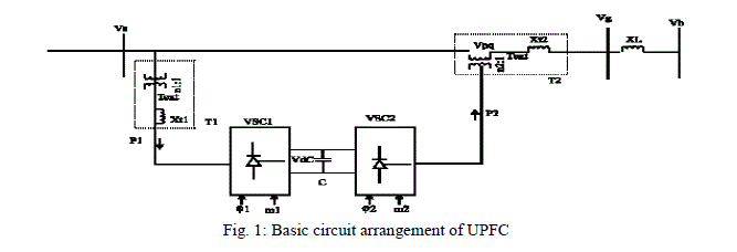 |
| The dc terminals of the two inverters are connected together and their common dc voltage is supported by a capacitor bank The series inverter is controlled to inject a set of synchronous voltages, Vinj, in series with the line In the process of doing this, the series inverter will exchange real and reactive power with the line The reactive power is electronically provided by the series inverter, and the real power is transmitted to the dc terminals The shunt inverter is operated in such a way as to demand this dc terminal power (positive or negative) from the line, thereby regulating the voltage, Vdc, of the dc bus The net real power absorbed from the line by the UPFC is thus equal to the losses of the two inverters and their transformers The remaining capacity of the shunt inverter can be used to exchange reactive current with the line. |
UPFC CONTROL |
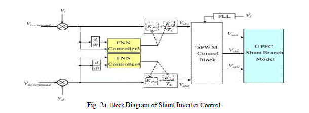
| Although the UPFC has many possible operating modes, it is anticipated that the shunt inverter will generally be operated in automatic voltage control mode and the series inverter will typically be in automatic power flow control mode. Accordingly, block diagrams are shown in Figs. |
 |
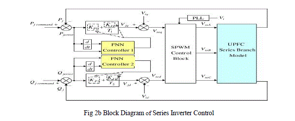 |
| It gives a greater detail of the control schemes for each inverter operating in these modes. It must be noted that these control schemes are typical but that they may vary in detail from one installation to another. Also, for clarity, only the most significant features are shown and less important signal processing and limiting has been omitted. The control schemes assume that both the series and shunt inverters generate output voltage with controllable magnitude and angle, and that the dc bus voltage will be held substantially constant. The automatic power flow control for the series inverter is achieved by means of a vector control scheme that regulates the transmission line current, using a synchronous reference frame in which the control quantities appear as dc signals in the steady state The appropriate reactive and real current components are determined for a desired Pref and Qreb compared with the measured line currents, and used to drive the magnitude and angle of the series inverter voltage. In this case the controlled current is the current delivered to the line by the shunt inverter In this case, however, the real and reactive components of the shunt current have a different significance The reference for the reactive current, iqshunt, is generated by an outer voltage control loop, responsible for regulating the ac bus voltage, and the reference for the real-power bearing current, ipshunt, is generated by a second voltage control loop that regulates the dc bus voltage. The control block diagrams shown in Figs 2a and 2b are only a small part of the numerous control algorithms that are needed for all the operating modes of the UPFC, and for protection and sequencing The control system typically incorporates many sophisticated computers and extensive electronics. |
DESIGN OF FUZZY LOGIC BASED CONTROLLER OF UPFC |
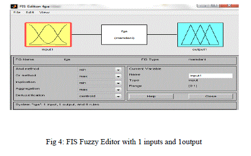
| There are two major types of fuzzy controllers, namely Mamdani type and Takagi- Sugeno (TS) type. The classification depends on the type of fuzzy rules used. If a fuzzy controller uses the TS type of fuzzy rules, it is called a TS fuzzy controller. Otherwise, the controller is named a Mamdani fuzzy controller. In order to damp of LFO effectively, in this section, for UPFC inputs, fuzzy controllers are designed. In the proposed method, Mamdani's fuzzy inference method is used, because it is the most commonly employed fuzzy methodology [9]. After the aggregation process, there is a fuzzy set for each output variable and finally they need to be defuzzificated. Angular velocity deviation (Δω) used as the fuzzy controller input. One of the UPFC inputs has been controlled via fuzzy controller output as shown fig. |
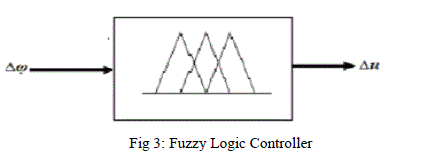 |
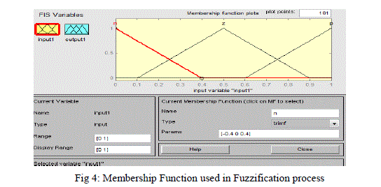
| For instance, the fuzzy block and membership functions for the inputs fuzzy controller are shown in Figures 4 and 5. Membership functions for the other controllers are similar to Figures 3 and 4; the only difference between these membership functions is the range of inputs and outputs for the fuzzy controllers. |
 |
 |
MODELLING OF THE MULTI-MACHINE INTEGRATED POWER SYSTEM |
| The integrated multi-machine power system model consisting of 4 generators used for the simulation purposes is shown in the form of a one line diagram (single line diagram) with & without the controllers in the Figs. 3 & 4 respectively. The generators 1, 2,3 and 4 are connected to buses 1, 2,3 and 4. UPFC is used for controlling & damping the power system oscillations in the integrated plant. One is connected between bus 9 & 10 Three transformers T1 to T3 are also used in the integrated power system near the generator buses for the power transmission purposes, i.e., for stepping up & stepping down purposes. Transmission lines are connected between the buses 9-10. Since, we know that the power system is a dynamic one, definitely, it is a on-linear system. |
 |
 |
SIMULSATION RESULTS |
| In the given four simulation graph results are obtained with x-axis as time and y-axis as rotor speed (i.e. rotor speed Vs time). |
| 1. The second graph is also observed between same quantities for same system by considering PSS Controller. And in this case system damped nearly at 14.5sec. |
 |
| 2. The third graph is also observed between same quantities for same system by considering PSS in addition to UPFC controller. And in this case system damped at 12sec. |
 |
| 3. The fourth graph is also observed between same quantities for same system by considering Fuzzy in addition to UPFC controller. And in this case system damped at 4.5sec. |
 |
CONCLUSION |
| In this paper, a nonlinear variable gain PSS controller for UPFC with improved fuzzy parameters has been proposed. The controller parameters are designed using an efficient version of the Mamdani fuzzy control scheme. UPFC in modeling is the amplification part of the conventional controller being modified by the fuzzy coordination unit, thus increasing the power system stability. From the simulation results it was observed that without the Fuzzy-UPFC controller, the 12 bus system will be having more disturbances, while we check the rotor speed on the first generator. There are lot of ringing oscillations (overshoots/ undershoots) & the output takes a lot of time to stabilize, which can be observed from the simulation results. But, from the incorporation of the Fuzzy-UPFC coordination system in loop with the plant the system stabilizes quickly, thus damping the local mode oscillations and reducing the settling time immediately after the occurrence of the fault. The developed control strategy is not only simple, reliable, and may be easy to implement in real time applications. |
References |
|