ISSN ONLINE(2278-8875) PRINT (2320-3765)
ISSN ONLINE(2278-8875) PRINT (2320-3765)
Dr.Soni Changlani1, Niketan Mishra2 and Vikram Singh Yadav3
|
| Related article at Pubmed, Scholar Google |
Visit for more related articles at International Journal of Advanced Research in Electrical, Electronics and Instrumentation Engineering
In the conventional amplifier there is two way conversion of the signal which is totally eradicated in the network which no-doubt enhance the overall performance of the DWDM in the long haul networks with the use of the modern optical amplifier. In this paper we optimise the gain of the 8 DWDM channel over entire conventional band i.e. C band. The gain flattening is done with the help of the Gain Flattening Filter (GFFs) as well as DCF. Numerical simulation result shows that both techniques can minimise unevenness of gain in all the prescribed WDM channels.
Keywords |
| EDFA, gain flatness, Gain Flattening Filter (GFFs), DCF, DWDM. |
INTRODUCTION |
| Erbium doped fiber amplifiers have had a major impact in the field of light wave communications. Optical amplifiers have contributed to the growth of a fifth generation of optical communication systems. But as the demands on the networks increased techniques like Dense Wavelength Division Multiplexing (DWDM) were developed. The performance of DWDM in long haul communication networks improved because of the fact that amplifiers were available that could amplify the wavelengths used in the network without requiring any conversion of the optical signal to the electrical signal. The importance of EDFA’s is due to their compatibility with the fiber network, low insertion loss, polarization insensitivity, high gain levels and near quantum limited noise performance[4]. |
| In DWDM transmission systems and their related optical networks, one of the key technological issues is the achievement of broad and flat gain bandwidth for Erbium Doped Fiber Amplifiers (EDFA’s). Gain differences occur between optical channels having large wavelength spacing (e.g. Δλ Ãâ¹ÃÆ1nm). In long amplifier chains, even small spectral gain variations (e.g. ΔG < 0.75 dB) can result in large differences in the received signal power, causing unacceptably large BER discrepancies between received signals [4]. For some optical channels, complete power extinction can occur at the system output, due to insufficient gain compensation along the amplifier chain. Additionally, the ASE generated in the region of highest gain (i.e., near λ = 1530 nm) in un-equalized EDFAs causes homogenous gain saturation, which affects WDM channels at longer wavelengths [1]. |
| Uniformity of gain involves two aspects, namely gain equalization and gain flattening. Gain equalization means achieving identical gains for a discrete number (two or three) of optical channels. Gain flattening means achieving a spectrally uniform gain bandwidth. Gain equalization can be achieved with requiring gain flattening. For example, given an EDFA of length L, the pump power can be chosen such that the gains at two different wavelengths become exactly equal due to signal re-absorption at short wavelengths. This method though useful does not work under saturated operating conditions. Later methods to flatten the gain using hosts such as fluorozirconate glass were investigated. It was found that the gain spectrum for these fibers though more uniform did not provide high pump efficiency. Therefore, these methods were not investigated any further. |
TECHNICAL BACKGROUND OF EDFA |
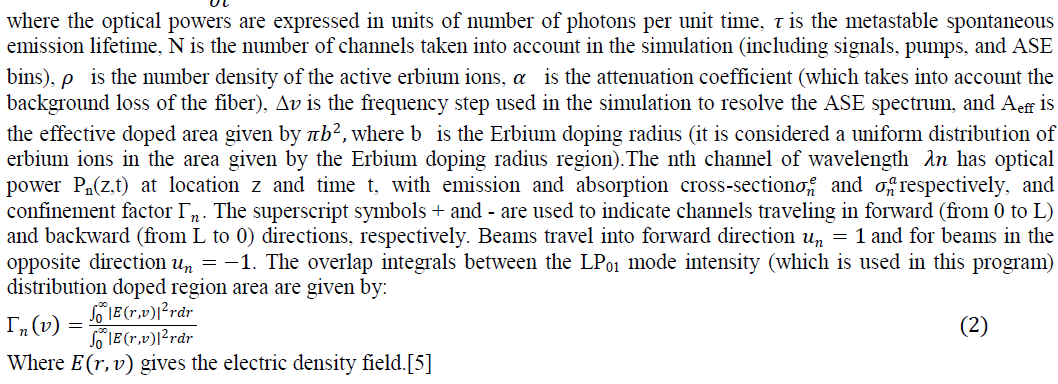
| The routines in EDFA numerically solve the rate equations coupled with propagating equations under stationary conditions. It is assumed a two-level Erbium system approximation and the rate equations are based on the energy level diagram. The same expressions described in the module Erbium Doped Fiber are adopted by this model. The main difference is related to the amplifier pump scheme selection. You can choose co-propagating, counter-propagating, or bi-directional pump schemes with the option to set wavelength and pump power. Geometrical Erbium-doped fiber parameters and cross-section curves are required as input files. As output files, you can access gain, output power values, and noise figure determined in the ASE bandwidth set as noise input data. [5] |
ERBIUM DOPED FIBER RATE AND PROPAGATION EQUATIONS |
 |
 |
THEORETICAL ASPECT OF GAIN FLATTENING FILTER (GFF) |
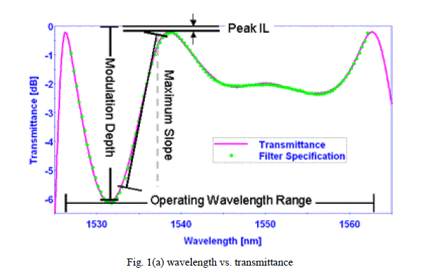
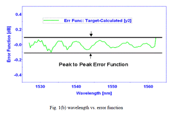
| Gain Flattening Filter (GFFs), also known as gain equalizing filters, is used to flatten or smooth out unequal signal intensities over a specified wavelength range. This unequal signal intensity usually occurs after an amplification stage (e.g., EDFA and/or Raman) .Typically, GFFs are used in conjunction with gain amplifiers to ensure that the amplified channels all have the same gain. The quality of a GFF is best described by the peak-to-peak error function (PPEF) because it represents the maximum flatness of the transmitted signal. The PPEF is calculated by comparing the spectral performance of the manufactured filter to the target curve specification. In general, the factors that determine the minimum PPEF that can be achieved are the maximum slope and the smoothness of the target curve. Some applications require multiple flattening regions or the addition of pass band outside the flattening region; these may increase the complexity of the filter. The wavelength domain specified in the gain equalizing target typically defines the operating range [Start, End] [6]. |
 |
 |
SETUP MODEL |
| Our proposed model is shown in the figure which consists of the WDM transmitter having the frequency of the 1525 nm with the spacing of the 5 nm at -20 to 10 dB power. The signal is then routed to the WDM MUX whose properties are almost same to that of the WDM transmitter having the bandwidth of 20 GHz. The signal is than passed through the optical fiber through the EDFA. The WDM MUX receives the signal at the ONU side after passing through the GFF. The property of the ONU WDM DMUX is similar to the transmitter. Finally the signal is retrieved by the photodetector. The proposed model is shown in the fig. 2(a) and fig. 2(b) |
 |
RESULT AND DISCUSSION |
| As we know that we use DCF as well as GFF as a gain flatting device, so on the basis of these some experimental results have been obtained. Results obtained are on the basis of unidirectional DWDM/WDM for 8 users. Downlink data is transmitted at the wavelength of 1525 to 1560 nm and the bit rate 1 Gbps to 10 Gbps. The wavelengths from 1525 to 1560 nm are because these wavelengths used for proper functioning of EDFA. In downlink, to improve the performance of DWDM/WDM we placed a DCF/GFF in between the transmitter and optical fiber. Results are obtained by changing laser power length is shown. |
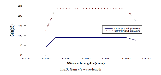 |
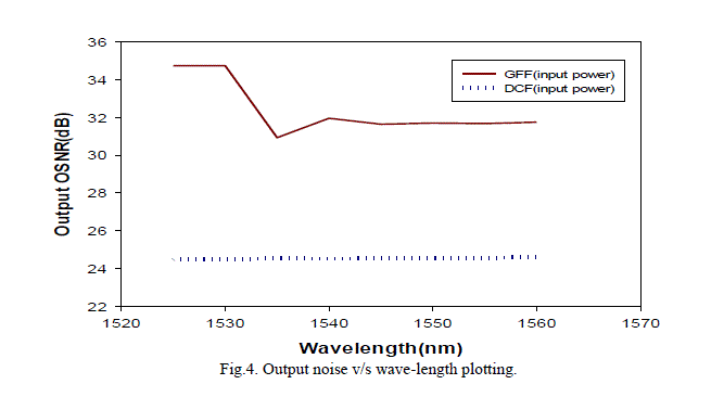
| A band of spike is visible at the range of 1530 to 1540 nm wavelength due to the ASE of the EDFA in case of GFF model, But in DCF model the entire range get flattened. The fig.4 is the plotting between the output noise and the wavelength of the overall system. This spike is responsible for producing the variation of 4 dB at 1530 nm wavelength. |
 |
CONCLUSIONS |
| In this paper we successfully demonstrate flattened the gain of the EDFA which is the vital issue in the DWDM long haul communication. In proposed design we optimised the gain of DWDM channels over conventional band through different techniques. But DCF compensation technique having higher noise figure as compare to GFF technique, due to this higher noise figure the DCF model not suitable for larger number of channels as well as higher data rate. |
References |
|