ISSN ONLINE(2319-8753)PRINT(2347-6710)
ISSN ONLINE(2319-8753)PRINT(2347-6710)
Anu Retnakar 1, Jayasree Ramanujan 2, Ajin A.S 3
, G. Jeganlal 4
|
| Related article at Pubmed, Scholar Google |
Visit for more related articles at International Journal of Innovative Research in Science, Engineering and Technology
Satellite launch vehicle puts an artificial satellite in orbit to circle round the earth and is used for communication and remote sensing. The upper stages of many launch vehicles are cryo stages i.e., stages that use liquid hydrogen LH2 and liquid oxygen LOx as propellants to generate thrust. Since liquid hydrogen is at -253°C and liquid oxygen is at -193°C, the tank material should have sufficient ductility and fracture toughness at low temperature apart from high specific strength. The tanks contain the propellant under pressure and are subjected to flight, axial, shear and bending loads, since they form part of the core vehicle. The tanks are to be designed for pressure, flight loads and thermal loads. They have to be extremely light and reliable. Axisymmetric modelling and analysis of the cryo propellant tank containing liquid hydrogen is done by using ANSYS. Geometric nonlinear analysis was performed & the equivalent von Mises stress exceeded ultimate strength
Keywords |
| Propellant tank, Axisymmetric modelling, Stress analysis, Geometric nonlinear analysis. |
INTRODUCTION |
| Propellants consist of a fuel and an oxidiser, which are burned to produce thrust in rockets. Propellants are stored in propellant tanks. Common tank materials are aluminum, stainless steel, titanium, alloy steel and fiber-reinforced plastics. The optimum shape of a propellant tank is spherical. Most of the tanks are cylindrical with half ellipses at the ends, they can be irregular in shape as well. Cryogenic propellants cool the tank wall temperature. These tanks are usually thermally insulated. External insulation layers have to be provided inorder to prevent moisture from being condensed inside the insulation layer. In 1991 Craig A. Stephens et. al. [1] developed one-dimensional and two-dimensional finite-difference thermal models of fuel tanks to simulate the thermal response and assist in the design of the generic research cryogenic tank. David Heckman [3] performed finite element analysis of pressure vessels, especially in determining stresses in local areas such as penetrations, O-ring grooves. He tested three dimensional, symmetric and axisymmetric models. Seo Young Kim et. al. [4] performed thermal analysis to design a high-performance liquid hydrogen (LH2) vessel. Analysis included the combined insulation of multi-layer insulation (MLI) and vapour-cooled radiation shield (VCS) under high vacuum. This paper presents the finite element modelling of a liquid hydrogen tank using ANSYS. Plane 82 element was used for axisymmetric modelling. Nonlinear analysis considering geometric nonlinearity was done. Hoop, meridional and von Mises stresses and radial displacement in the tank were identified and checked with the theoretical values. |
CONFIGURATION OF LH2 TANK |
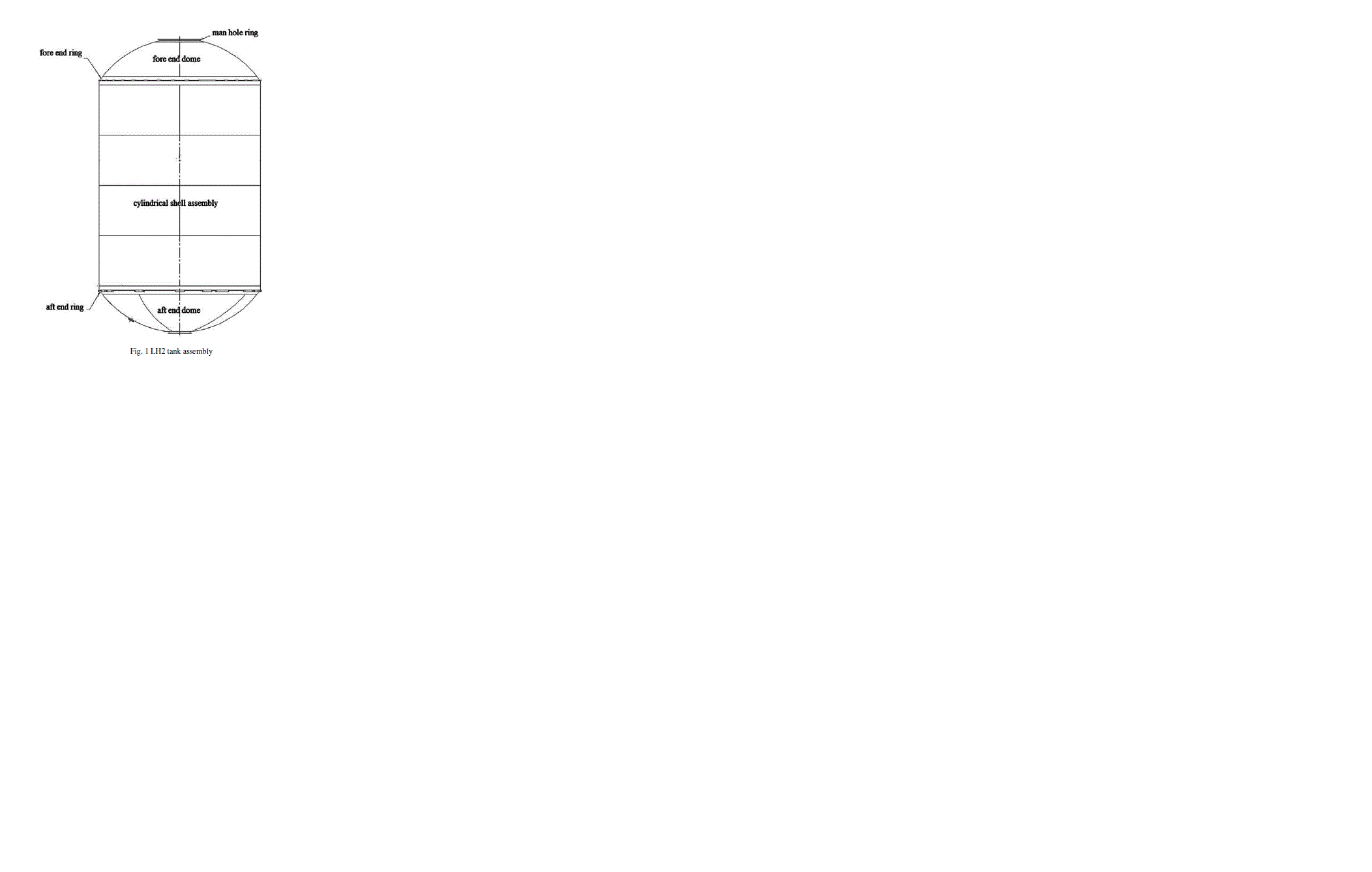
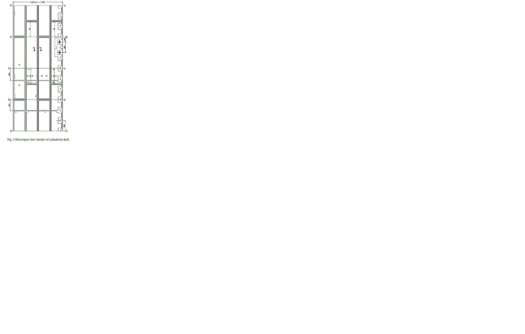
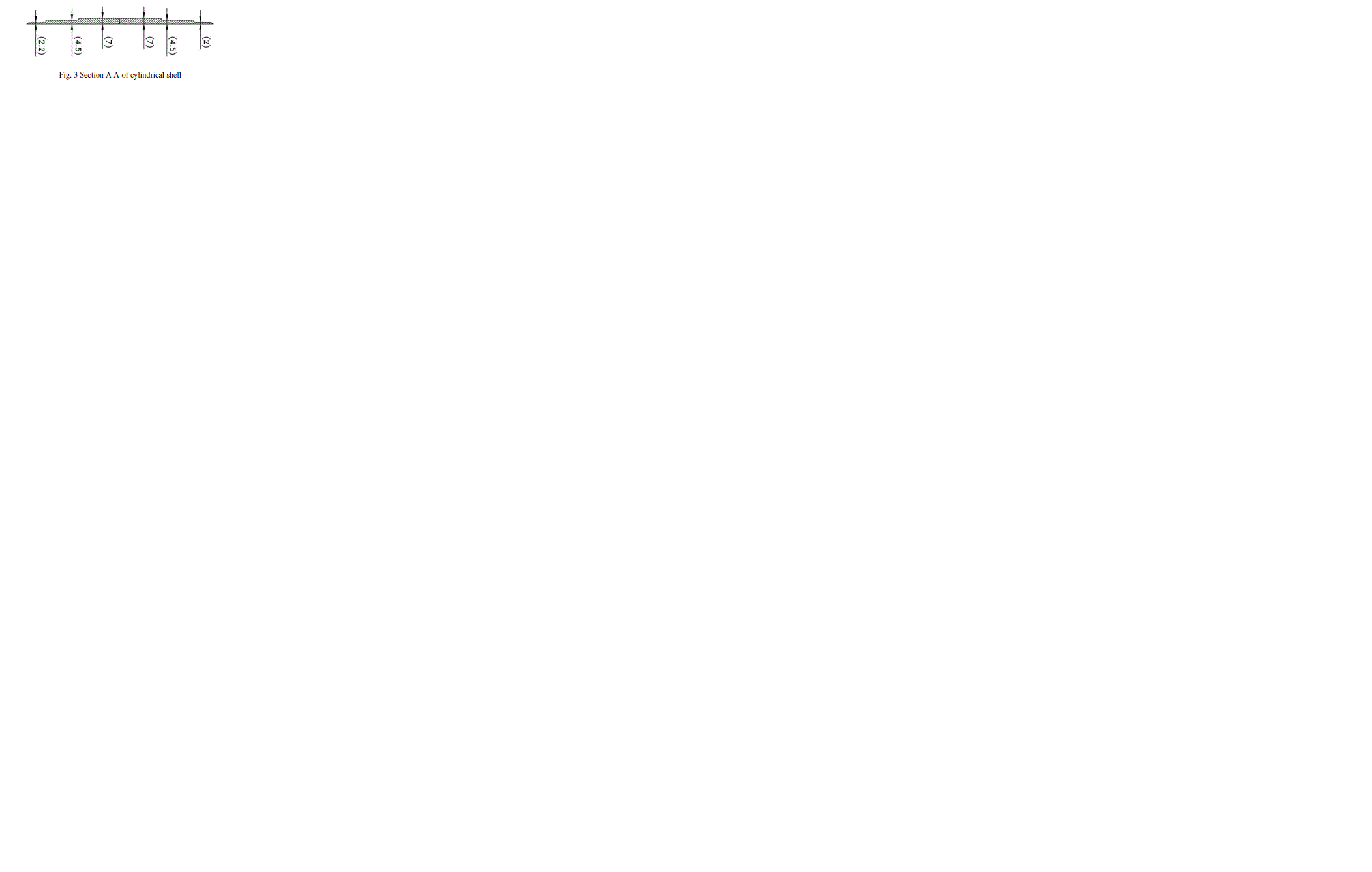
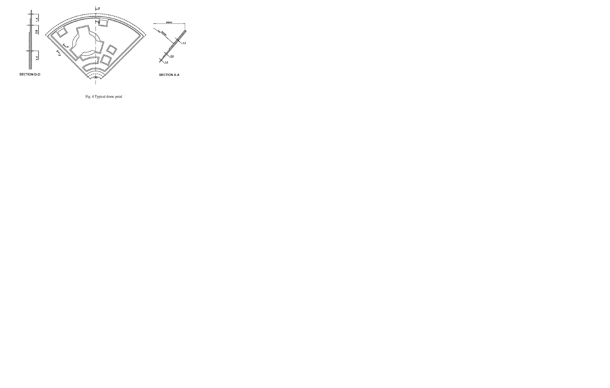
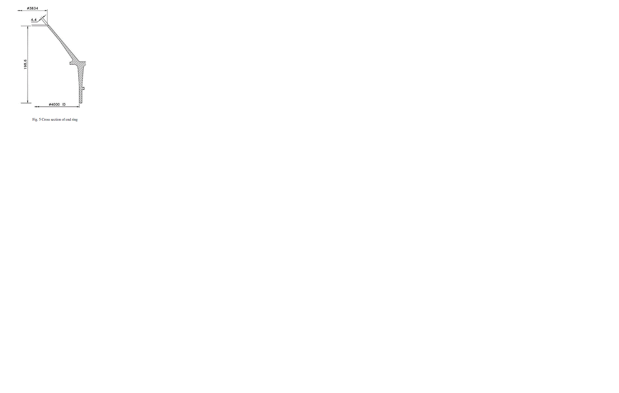
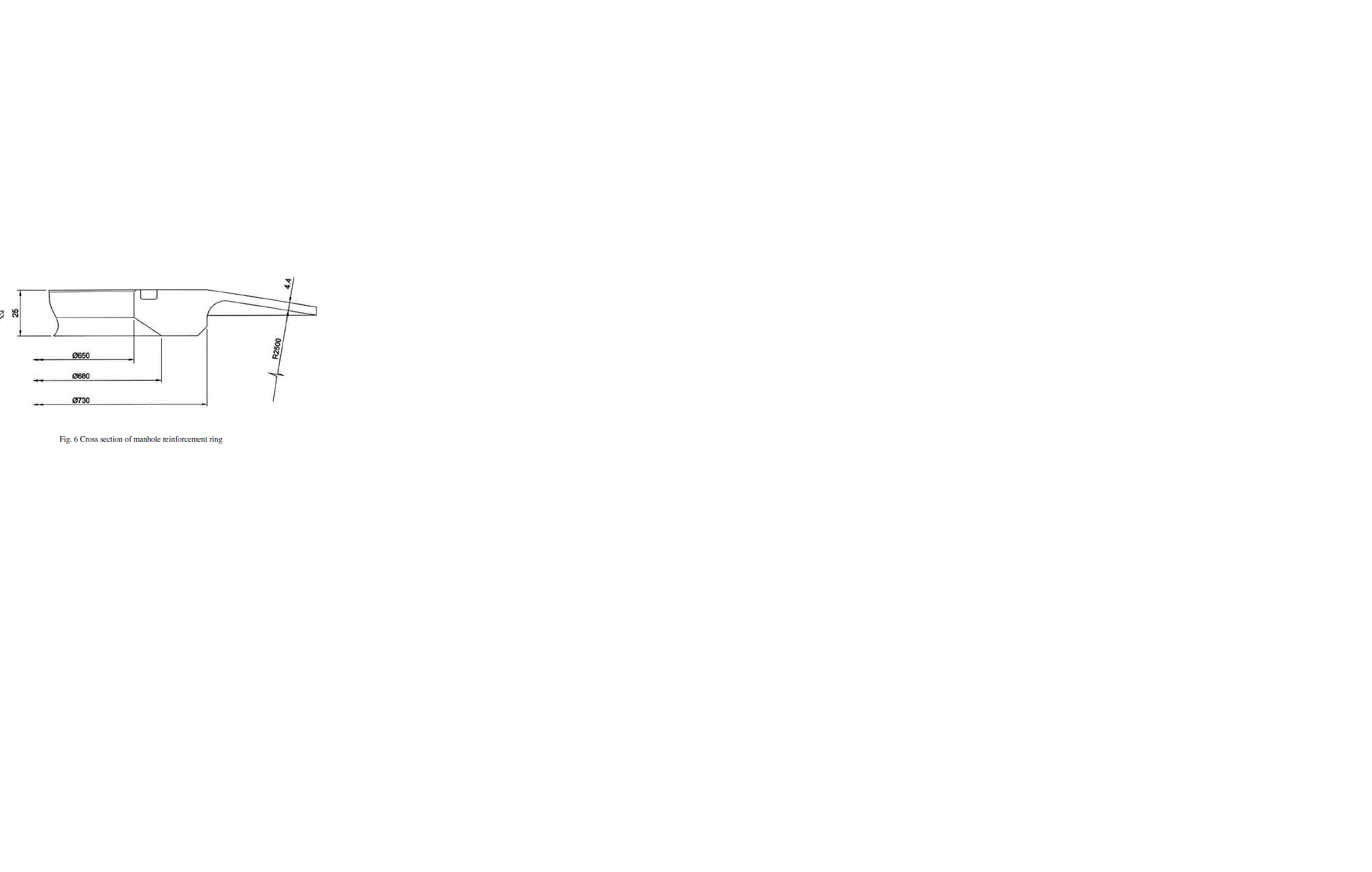
| Liquid hydrogen is the liquid state of element hydrogen having a specific gravity of 0.07. Boiling point of LH2 is - 252.882°C. The very low fuel density requires bulky fuel tanks. The tank is made of AA2219 material. It is cylindrical with spherical end domes. The tank consists of a cylindrical shell, fore and aft end domes, fore and aft end rings and manhole reinforcement rings. The tank assembly is shown in Fig 1. There is a manhole cover at the centre of the fore end dome. There are two nozzles at the cylindrical shell for mounting the gas bottle. The shell assembly is attached to the dome portion of the tank using Y rings at both ends. The end rings are the interface between the cylindrical shell and the spherical end domes. The rings also provide the interface for the adjacent structural elements as well as the interface for handling. Fig. 5 shows the cross section of the end ring. Higher thickness of 7 mm is provided at the weld regions of the shell. The material away from weld regions of the shell sectors are chemically milled to 2 mm (minimum) to reduce the mass. Fig 2 & 3 shows the developed view (inside) of cylindrical shell & section A-A of cylindrical shell respectively. Higher thickness of 4.4 mm is provided at the weld regions of the domes. The material away from weld regions of the domes is chemically milled to 1.4 mm (minimum) to reduce the mass. Fig. 4 shows typical dome petal of the tank. Fig. 6 shows the cross section of manhole reinforcement ring. This ring is bolted to the fore end dome. The manhole cover is bolted to the ring after internal piping and electrical works inside the tank is over. The proof pressure of the tank is 3.4 bar. |
 |
 |
AXISYMMETRIC MODELLING |
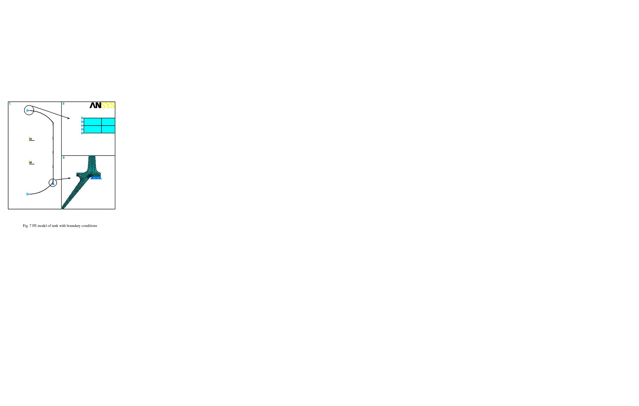
| The global cartesian Y axis is assumed to be the axis of symmetry. The radial direction is in the +X direction. Axisymmetric PLANE 82, 2-D, 8 noded structural solid elements were used for meshing geometry. Taking advantage of symmetry half model of the tank is used for FE analysis. An internal pressure of 0.34 MPa was applied.Nodes at the global cartesian Y axis are constrained in X direction to simulate the axisymmetric effect. Few nodes at the bottom of the aft end ring were constrained in Y direction. Fig. 7 shows FE model of the tank with boundary conditions. Fig. 8 & 9 shows finite element mesh details and internal pressure distribution in the tank respectively. |
 |
 |
RESULTS & DISCUSSION |
| The problem was analysed by applying the load in 10 substeps. Fig. 10 shows the deformed shape whereas Fig. 11, 12 and 13 shows the hoop, meridional and von Mises stress plots respectively. Fig. 14 shows the radial displacement of the tank. Table 2 shows the stresses and displacement values obtained. |
 |
| Location of max eq. stress : Chemical milling step at the manhole to fore end dome portion where thickness changes from 2.8 mm to 1.4 mm. |
| The hoop stress, meridional stress and radial displacements matches with the theoretical values. |
 |
 |
 |
CONCLUSION |
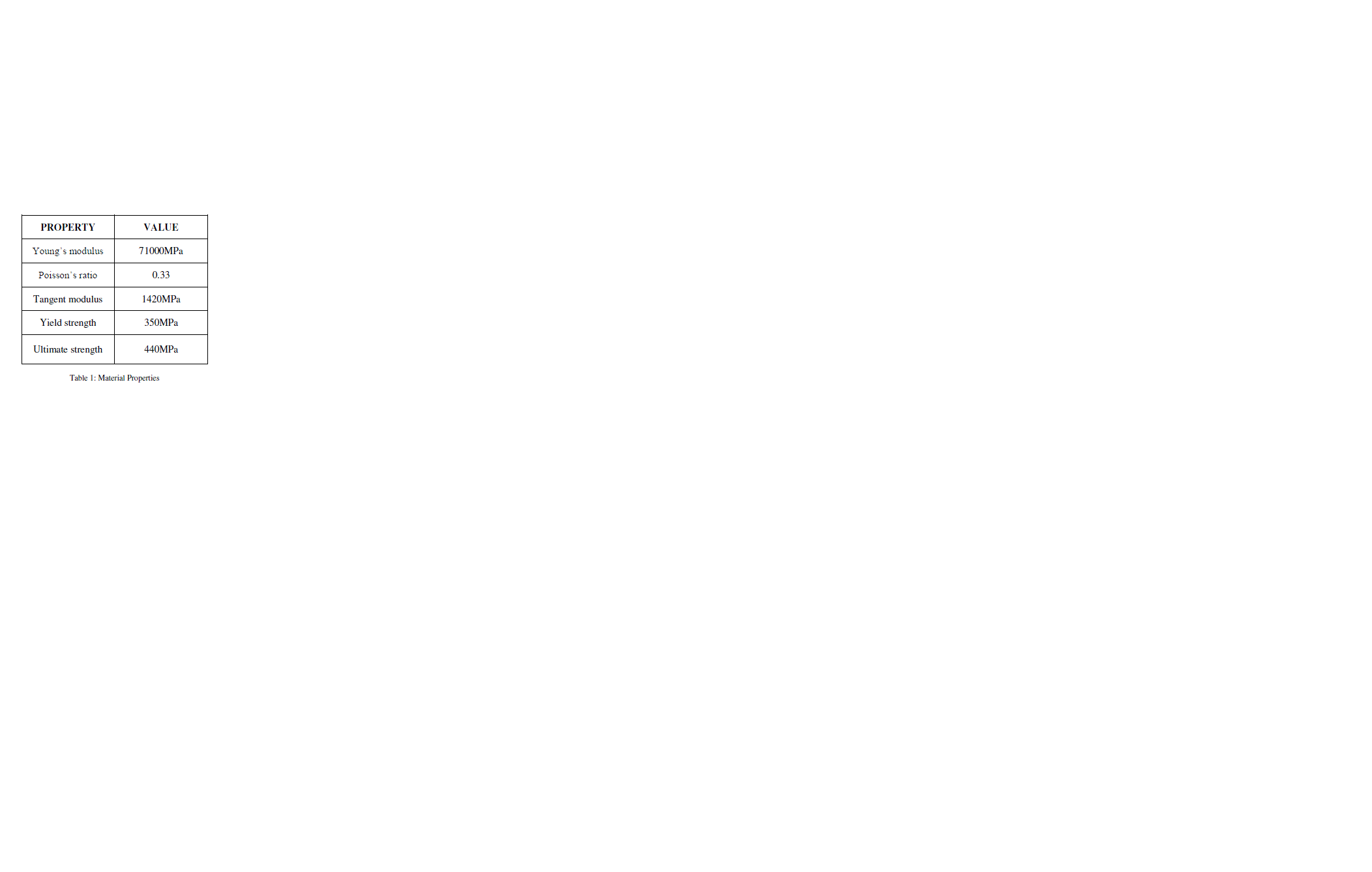
| Since the maximum stress has been observed at the chemical milling step in the manhole to dome portion, it is the critical location at which failure will occur. The von Mises stress in the tank is 597.963MPa. Since this value is greater than the yield strength of the material, i.e, 350MPa, the material will start yielding. It is also greater than the ultimate strength, i.e, 440 MPa. Hence the material will undergo failure. Hence it can be concluded that as the equivalent von Mises stress has exceeded the ultimate tensile strength, the structure will fail. Hence the design is not safe. |