ISSN ONLINE(2319-8753)PRINT(2347-6710)
ISSN ONLINE(2319-8753)PRINT(2347-6710)
K.Anil Pradeep1, C.V.Siva Rama Prasad2
|
| Related article at Pubmed, Scholar Google |
Visit for more related articles at International Journal of Innovative Research in Science, Engineering and Technology
Industrial Chimneys are generally intended to supportcritical loads produced by seismic activity and wind.So it is essential to evaluate the dynamic response of chimney to seismic activity and wind loads.Response to Earthquake and wind are more critical as chimney is a slender structure.The present paper will analysethe 60m reinforced concrete chimney. Comparison has been made for wind and seismic analysis.Seismic analysis is done as per IS 1893(part 4): 2005 and wind analysis as per Draft Code CED38(7892):2013 (Third revision of IS 4998(part 1):1992).Further study continues on deciding the governing loads for chimneys for the loads considered.
Keywords |
| RCC Chimneys, Earthquake loads, Wind loads, Combineddesign loads, Seismic analysis, Wind analysis, Draft code. |
I.INTRODUCTION |
| Chimneys are the structures which are built to greater heights as tall slender structures. In early days, as household vents and over the years; they are popularly known as chimneys [1].Chimneys or stacks are used as a medium to transfer highly contaminated polluted gases to atmosphere at greater heights.Over the years due to development of large scale industries, a large number of tall slender chimneys are required to be designed every year. The main function of chimney is to take highly poisonous gases which are not acceptable at ground level were taken to greater heights with sufficient velocities. Chimneys are more vulnerable to wind and earthquake loads which may cause severe problem in power plants and major industries. However, if they located in higher seismic zone with lower windspeeds, then, seismic forces may become analogous, if not more, than the wind loads. It is designed for both,along wind and across wind loads. In this paper procedure given by draft Code CED 38(7892):2013 (third revision of IS 4998(part 1):1992)[2] is being used to obtain the combined design loads.In this paper of 60m RCC chimney for design seismic loads and wind loads; both are compared to decide the governing loads for the designof chimney shell. By ensuring proper design and construction, chimneys will betreated as self-standing structures to resist earth quake forces and wind forces acting on them. It is a general method to reflect the effects of wind and earthquake distinctly in the design. |
II.LITERATURE REVIEW |
| Present literature review is carried out on the analysis of RCC chimneyfor wind and seismic effects. |
| Menon and Rao(1997) reviews the code measures to estimate the across wind response of reinforced concrete chimney. In this paper, the difficulties in the codal evaluation of across wind moments and load factor provisions are examined through reliability approach. This paper mainly suggest that it is essential to design at certain conditions for the across wind loading[3]. |
| K.R.C. Reddy, O.R.Jaiswal and P.N.Godbole (2011) discusses about wind and earthquake analysis of tall reinforced concrete chimney. In this paper two reinforced concrete chimneys are analysed for wind and earth quake loads. Earth quake analysis is done as per IS 1893 (part 4): 2005 and wind analysis is done as per IS 4998 (part 1): 1992. The combination of along & across wind loads of chimney is done as per ACI 307-98 code. Finally they computed the governing load for design of chimneys [4]. |
| B. SivaKonda Reddy, C.Srikanth, V.RohiniPadmavathi (2012) discusses about wind load effects on tall reinforced concrete chimneys. In this paper they considered 275m reinforced concrete lined chimney. The study of this paper is along &across wind effects on this RCC Chimney for I and VI wind zones of India. Finally they concluded that, for wind zone –I across wind loads are governing and for wind zone-VI along wind loads are governing rather than the across wind loads [5]. |
| K.R.C. Reddy, O.R.Jaiswal and P.N.Godbole (2012) discusses about combined design moments of tall reinforced concrete chimneys. Combined design moments along and across wind response of chimneys are considered for the design as wind load governs the design of RC chimneys. The methods used for evaluation are IS 4998, ACI 307, AS/NZS11702&Menon&Rao [6]. |
| M.G.Shaikh, Mie, H.A.M.I.khan discusses about governing loads for design of a tall RCC chimney.Generally, this type of design requires dynamic analysis for loads due to self-weight, earthquake and wind.The main focus is to compare the wind loads with seismic loads. For along wind, wind analysis is done by peak factor method andfor across wind by random response method [7]. |
| Based on literature review, most of the chimneys designed are based on IS 4998:1992 but in this paper response of chimney was evaluated based on draft Code CED 38(7892):2013 (third revision of IS 4998(part 1):1992) |
| Details of the chimney as follows, |
| 1. Height of the chimney – 60m |
| 2. Outerdiameter of chimney at bottom – 5.455m |
| 3. Outer diameter of chimney at top – 3.273m |
| 4. Thickness of shell at bottom –0.15m |
| 5. Thickness of shell at top – 0.15m |
| 6. Thickness of air gap – 0.08m |
| 7. Thickness of fire brick lining – 0.1m |
| 8. Grade of concrete – M25 |
| 9. Height to base diameter ratio – 11 |
| 10. Top diameter to base diameter ratio – 0.6 |
| 11. Basic wind speed – 55m/s |
| 12. Foundation type – RCC circular mat |
| Description of loading: |
| Density of various materials considered for design, |
| Concrete – 25kN/m3 |
| Insulation – 1kN/m3 |
| Structural steel – 78.5kN/m3 |
| Live load – 5kN/m3 |
| Wind load: |
| The following wind parameters are followed in accessing the wind loads on the structure |
| Basic wind speed – 55m/s |
| Terrain category -2 |
| Class of structure – c |
| Risk coefficient k1 – 1 |
| Topography factor k3– 1 |
| K2 factor taken from Draft Code CED 38(7892):2013 (third revision of IS 4998(part 1):1992) |
| Earthquake force data: |
| Earthquake load for the chimney has been calculated as per IS 1893(par 4) : 2005 |
| Zone factor – 0.16 |
| Seismic zone – III |
| Importance factor (I) – 1.5 |
| Reduction factor (R) - 3 |
| Analysis procedure for wind load as per Draft copy CED 38(7892):2013 (third revision of IS 4998(part 1):1992) |
III.ESTIMATION OF WIND LOADS |
| In tall structures like industrial chimneys, wind forces usually govern the design. Wind effect can be divided into two components. Those are along wind and across wind effects. Due to drag force on chimney, along wind loads occur. Due to lift force on chimney, across wind loads occur.When wind forces acts on the structure, buffeting effect is produced because ofalong wind loads. For the reason of evaluation of loads, the chimney is designed as a cantilever whose bases fixed to the ground. Generally wind does not blow at fixed rate. It blows at gusts.So this requires that the effects are taken in terms of equivalent loads. Here chimney is analysed as a bluff body having turbulent flow for the computation of along wind loads. Equivalent static procedure is used in codes known as gust factor method. Currently stipulated in all building codes and also inDraft Code CED 38(7892):2013 (third revision of IS 4998(part 1):1992). In this method wind pressure whichis assumed to be acting on face of the chimney, due to this wind pressures are considered as static wind loads. This is then improved using the gust factor to make sure of the dynamic effects. The following codes used in estimation of along wing loads are: |
| • IS875 (part 3):1987 - code practice for design loads for building and structures [8]. |
| • Draft Code CED 38(7892):2013 (third revision of IS 4998(part 1):1992) |
Design wind pressure: |
| The design wind speed, V (z) can be calculated by multiplying basic wind speed, Vbwith modification factors, k1, k2andk3. |
 |
Calculation of along wind loads: |
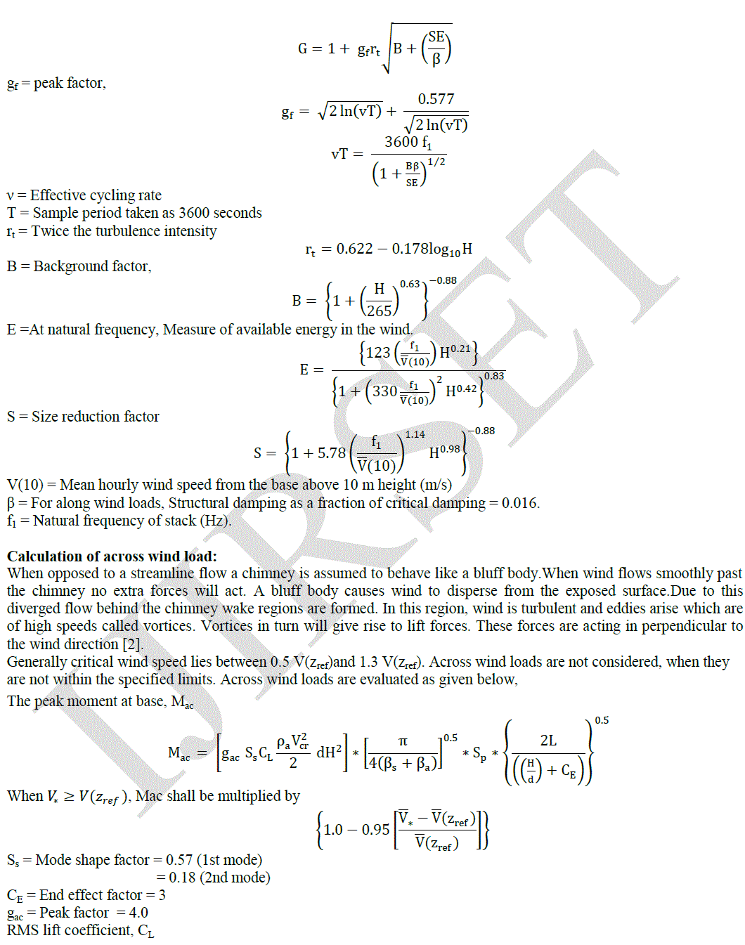
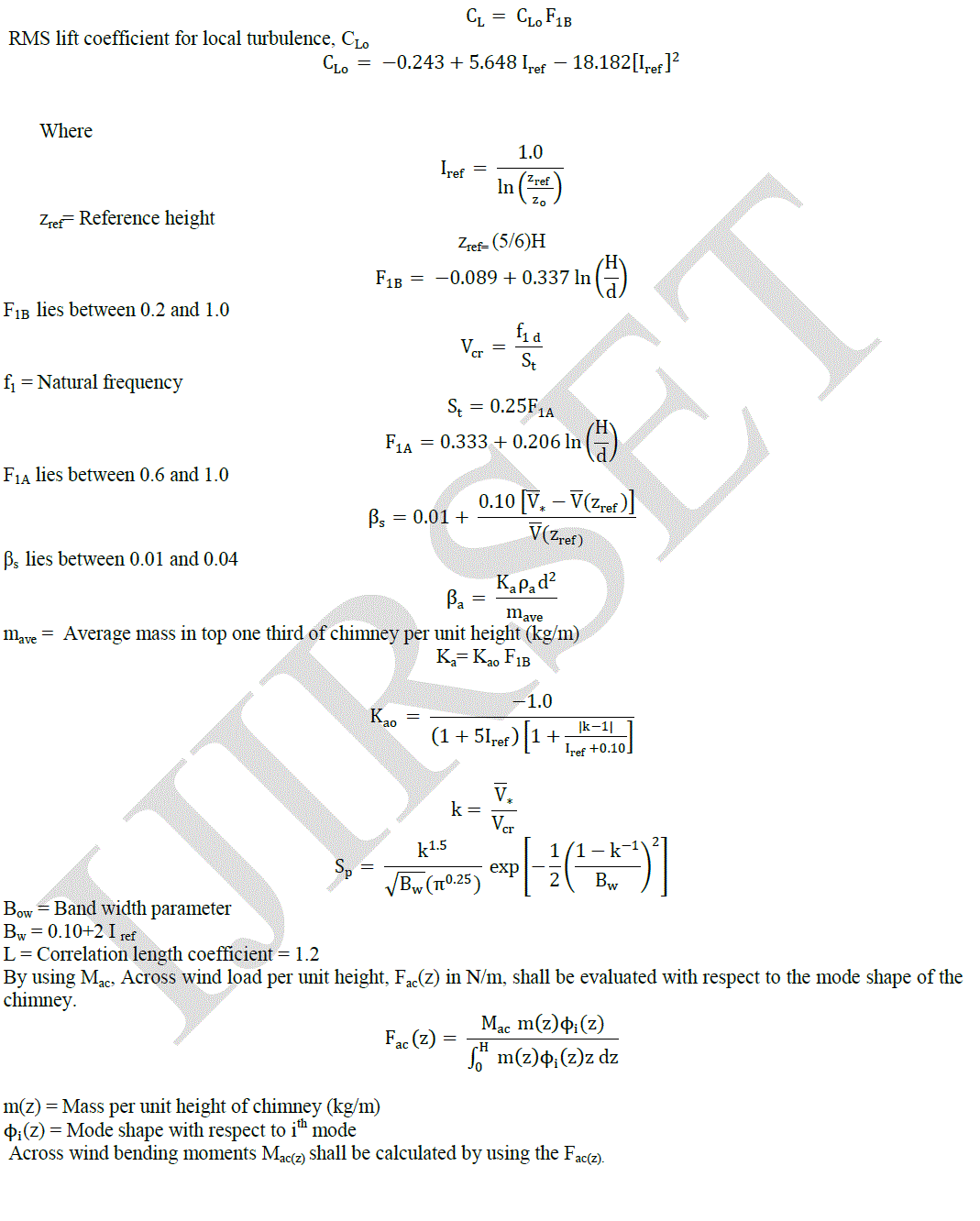
| By using the gust factor approach, along wind loads are calculated. Generally, chimney height is divided into number of segments. Each segmentis not greater than 10 meters. Load can be calculated at any section by taking the average of loads above and below it. Considering the chimney like a cantilever structure, by using sectional forces, moments are evaluated[2]. |
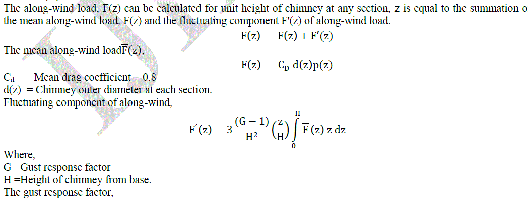
| The along-wind load, F(z) can be calculated for unit height of chimney at any section, z is equal to the summation of the mean along-wind load, F(z) and the fluctuating component F'(z) of along-wind load. |
 |
 |
 |
 |
IV.ESTIMATION OF EARTHQUAKE LOADS |
| For the calculation of earthquake loads, there are two methods available in Indian standards. These two methods are used to evaluate the design forces. Earth quake analysis was carried out by using 1893 (part 4): 2005 [9] |
Moment and Shear Force Calculation: |
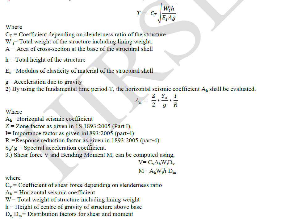
| For evaluation of moment and shear force, the following are required. |
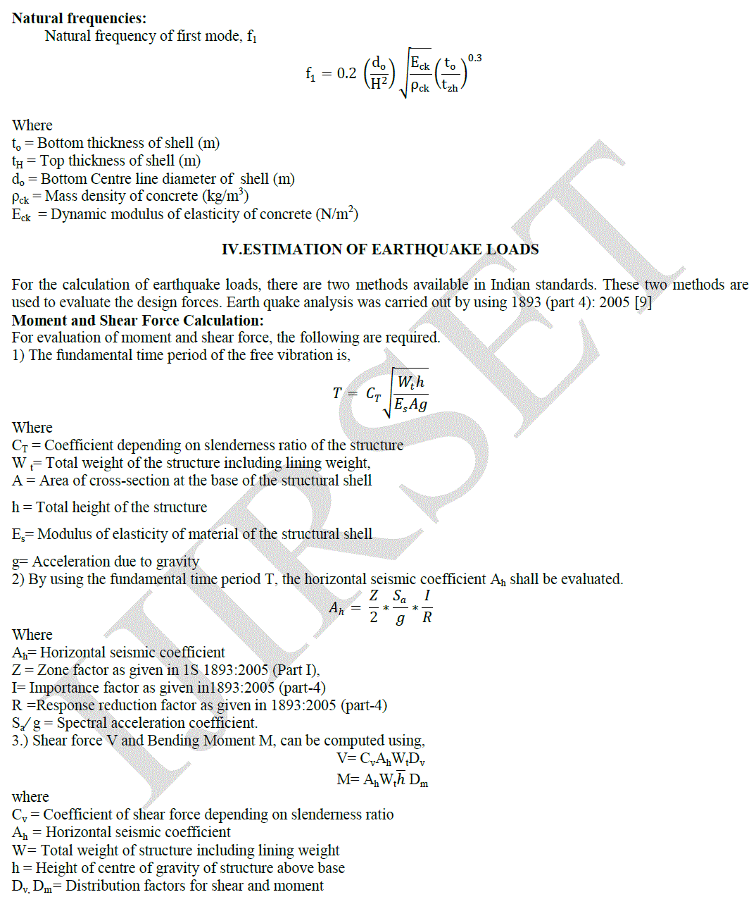
| 1) The fundamental time period of the free vibration is, |
 |
V.STAAD MODEL |
| For generatingchimney model in STAAD, two types of models were considered, one with 8 node solid elements and other one with line element. Both the models were analysed and deflection was calculated. It is found that the deflection value for the 8 node solid element model and the linear model are same, so for making the model generation easy linear element was chosen. Mode shapes and frequencies are calculated using STAAD. A factor of 1.2 was multiplied to take in to account of accessories of chimney to its self-weight[10]. |
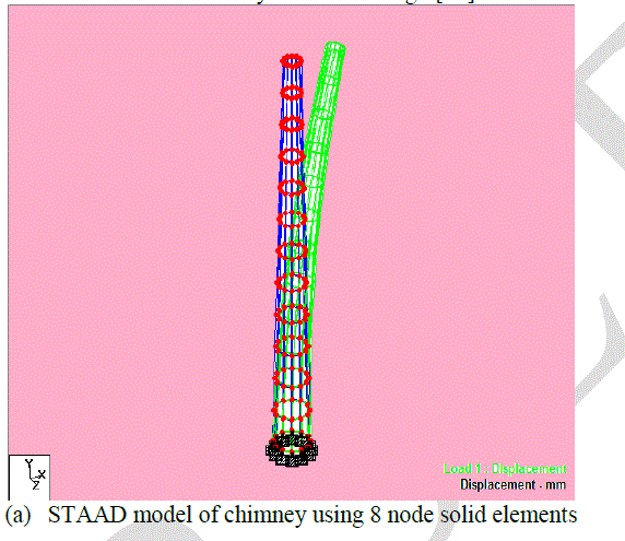 |
| In the above figure (a) STAAD model of chimney using 8 node solidelements, shows 60m chimney having fixed supports assigned to base elements and the topmost elements are left free to ensure cantilever action. Under the calculated horizontal forces the displacement of this chimney was noted to compare it with chimney model generated using linear/ beam element. |
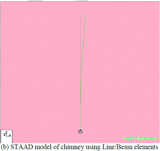 |
| In the above figure (b) STAAD model of chimney using Line/Beam elements, shows 60m chimney having fixed support assigned to base node of the bottom most element. Cross sections were assigned using tapered tube element. For the same horizontal load mentioned above this model was analysed for deflection. It is found that both the deflection values are same. Hence, for modal analysis linear element model was adopted for easier evaluation and interpretation of results. |
VI.EXPERIMENTALRESULTS |
 |
VII.CONCLUSIONS |
| • On studying the results presented in the above tables, it shows that as the zone factor increases the values of shear force and bending moment increases. |
| • The effect of wind force for 55m/s wind speed is quite significant as compared with the earth quake forces in Zone II and Zone III. |
| • Moment due to earthquake in Zone III is almost equal to the Combined Moment due to wind speed of 55m/s. |
| • As per draft code the deflection at the free end of the chimney should be well within the permissible limits. |
| • For 60m RCC Chimney of chosen geometric proportions, wind forces governing the design. |