ISSN ONLINE(2278-8875) PRINT (2320-3765)
ISSN ONLINE(2278-8875) PRINT (2320-3765)
Mrs. Ramalakshmi.T1, Mrs. Jerril Gilda. S2
|
| Related article at Pubmed, Scholar Google |
Visit for more related articles at International Journal of Advanced Research in Electrical, Electronics and Instrumentation Engineering
With ever increasing concern on energy issues, the development of renewable energy sources is becoming more and more attractive. In the past few years the photovoltaic and wind power generation have been increased significantly. Both energy flow and operation characteristics of wind / PV hybrid power systems are analysed to achieve its optimal and reliable operation. Here the proposed hybrid power generation system, applying advanced power control techniques feed to power sources; Wind power, solar power, storage battery. A photovoltaic (PV) based dynamic voltage restorer (DVR) is proposed to handle voltage sags and swells. Otherwise, it will operate as an Uninterruptable power supply (UPS) when the utility grid fails to supply. PV based DVR system is comprised of PV system with low and high power DC-DC Boost converter, PWM voltage source inverter, series injection transformer and semiconductor switches. The simulation study is carried out using MATLAB and results are presented.
Keywords |
| Wind power generation system, solar PV system, grid interface inverter, MPPT, storage battery, Dynamic voltage restorer (DVR), Voltage sag, Voltage swell, DC-DC converter, MATLAB. |
INTRODUCTION |
| In order to reduce the greenhouse gas emission from electric power generation system and for the growing demand of electricity, the environmental issues has led to one of the new trends of integration of renewable energy resources and energy storage systems. In particular, advantages in wind and PV energy technologies have increased their use in hybrid configurations, because of being emission-free and no cost of energy. Hybrid Wind/PV systems are one of the most efficient solution to supply power either directly to a utility grid or to an isolated load [1]. A wind turbine which converts kinetic energy into mechanical energy drives the wind generator to generate ac electric power, and it is converted into dc power to form the common dc link. Solar PV panel is a non linear power source, where the panel output power varies with temperature. Due to the low voltage of an individual solar cell (typically 0.6V), several cells are combined into photovoltaic modules, which are in turn connected together into an array[2]. The output voltage from the array is low when compared to the dc link. To raise the output voltage of the array, dc-dc converter is used. In this paper buck-boost converter is used. MPPT controller is used to track the peak power from SPV module [5]. The power extracted from the hybrid wind/PV system is transferred to the grid through a three - phase inverter at synchronized grid frequency |
II. PROBLEM FORMULATION |
| A. PV Generation System |
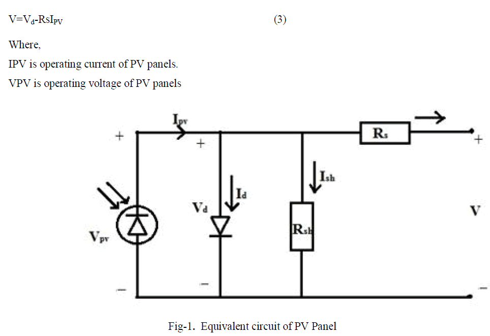
| A Photovoltaic cell can be represented by a current source connected in parallel with a diode. The equivalent circuit model also includes a shunt resistance (Rsh) and series resistance (Rs). The PV sizing variable comprises of size of a PV Panel and the number of strings in a PV array. The necessary number of PV panels to be connected in the series is derived by the number of Panels need to match the bus operating voltage. The output of PV panels must include the input of geographic location such as irradiation and temperature etc. Fig-1 shows the equivalent circuit of Photovoltaic panel. The output current and output power of Photovoltaic panels at any time‘t’ can be calculated as: |
 |
 |
B. MPPT algorithm |
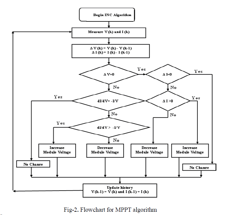
| MPPT algorithms are necessary in PV applications in order to obtain the maximum power from a solar array because the MPP (Maximum Power Point) of a solar panel varies with the irradiation and temperature. In this paper, Incremental Conductance (INC) algorithm is used for maximum power point tracking. The incremental conductance uses the PV array's incremental conductance dI/dV to compute the sign of dP/dV. It does this using an expression derived from the condition that, at the maximum power point, dP/dV = 0. Beginning with this condition, it is possible to show that, at the MPP dI/dV = - I/V. Thus, incremental conductance can determine that the MPPT has reached the MPP and stop perturbing the operating point. If this condition is not met, the direction in which the MPPT operating point must be perturbed can be calculated using the relationship between dI/dV and -I/V. The flowchart is shown in Fig-2. |
 |
C. Wind Turbine System |
| Wind turbine system the power from the wind by means of aerodynamically designed blades and convert it to rotating mechanical power. The energy and current of the wind turbine Generator for each instant are depend on local weather conditions and actual installation weight of the wind turbines. Wind turbines are usually connected in parallel, not in a series. The equivalent circuit of wind turbine is represented as shown in Fig-3. |
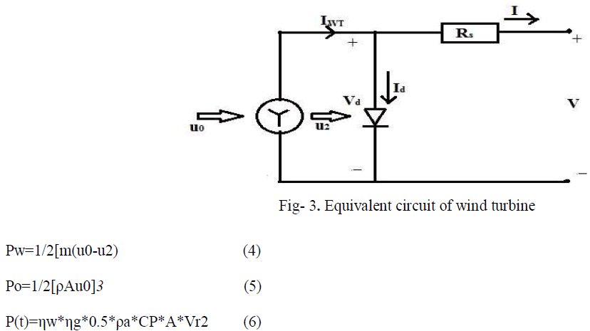 |
| Where, |
| Pw is the output power in watts |
| Pa is the extracted output from wind in watts |
| Pwt is the generated output power in watts |
| ηw is the efficiency of wind turbine. |
| ηg is the efficiency of generator. |
| ρa is the density of air. |
| CP is the power co-efficient of wind turbine. |
| A is the wind turbine swept area. |
D. STORAGE BATTERY |
| The batteries are used to store the excess energy during the low generation period. The equivalent circuit batteries are represented as shown the Fig-4. |
 |
E. Model of generator associated to the rectifier |
| Both induction and synchronous generators can be used for wind turbine systems. Mainly, three types of induction generators are used in wind power conversion systems: cage rotor, wound rotor with slip control and doubly fed induction rotors. In this project, gearless multi pole permanent magnet synchronous generator (PMSG) is chosen and it is attractive because it offers better performance due to higher efficiency and less maintenance since it does not have rotor current and can be used without a gearbox, which also implies the reduction of the weight of the nacelle, and reduction of costs. It produces electricity from the mechanical energy obtained from the wind. The wind turbine controller consists of three- phase diode bridge rectifier which converts the alternating current from wind turbine to direct current. The three phase diode bridge rectifier is comprised of six rectifier diodes. The variable frequency output voltages from wind turbines are rectified to unregulated dc voltages. |
III. MODEL OF HYBRID WIND/PV SYSTEM CONNECTED WITH GRID |
| A hybrid energy system usually consists of two or more renewable energy sources used together to provide increased system efficiency as well as greater balance in energy supply. In this project, the hybrid energy system is a photovoltaic array coupled with a wind turbine. Fig-5 shows the schematic diagram of proposed system |
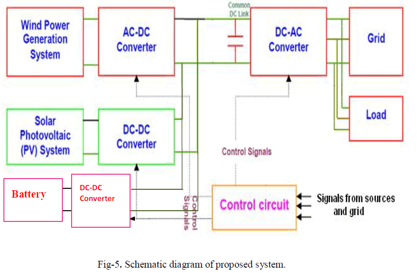 |
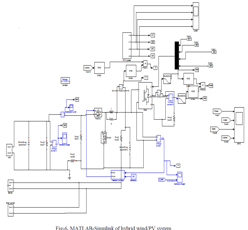
| The grid interconnection converts the variable frequency and magnitude outputs from the hybrid wind/SPV system to the synchronous frequency of the utility grid. The variable frequency and magnitude output voltages from the hybrid wind/SPV system are converted to DC voltages or so called DC links. The grid side inverter converts the DC link voltages to the synchronous voltages of the grid. A Sinusoidal Pulse Width Modulation (SPWM) is employed for generating gate pulse. Fig-6 shows the MATLAB - Simulink of hybrid wind/PV system connected with grid shown in Fig-6 |
 |
| The output of grid voltage and grid current are in phase and are expressed in per units (p.u). It is achieved by using Phase Locked Loop (PLL). The PLL consists of comprises of a phase detector (PD), a low-pass filter, voltage controlled oscillator (VCO) and a feedback divider. Figure-7 shows the output waveform of grid connected hybrid system. |
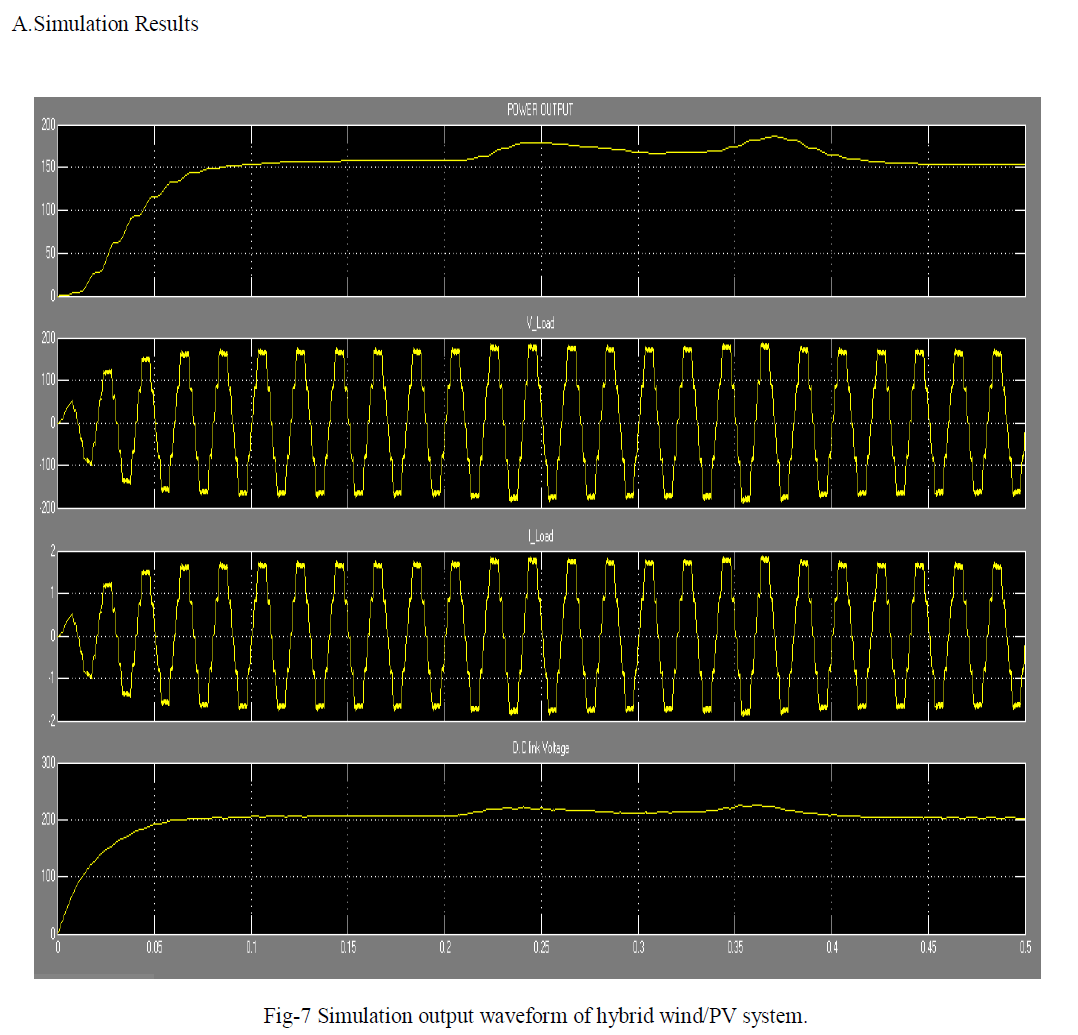 |
| Fig-7, shows the load voltage, load current, power output and DC link voltage wave form. It is combination of solar and wind. Here load is resistive load. The Load voltage is 200V AC and the load current is 2A and power output is 200w. |
IV. POWER QUALITY IMPROVEMENT BY USING DVR |
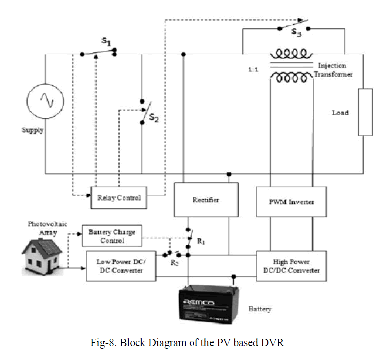 |
| The block diagram of the proposed PV based DVR is shown in Fig 8. The proposed system mainly consists of a photovoltaic array, low and high power DC/DC boost converters, battery, PWM inverter, series injection transformer, and semiconductor switches S1, S2, S3, R1 and R2. |
| An injecting transformer is connected in series with the load for restoring sag and swell, and is reconfigured into parallel connection using switches S1, S2 and S3 when handling outage. A DVR can compensate voltage drop across a load by injecting a voltage through a series injection transformer. The injected voltage is in phase with supply voltage. In normal condition, the supply voltage is equal to the load voltage with zero angle. During sag, the supply voltage decreases to a value less than its nominal value. The DVR reacts to the sag event and injects a compensating voltage Vinj in phase with the supply voltage to restore the voltage at nominal value. This method is very simple to implement, very fast especially in calculating the VR compensating voltage. The injected voltage of a DVR (VDVR) can be expressed as, |
 |
| The inverter is a core component of the DVR. Its control will directly affect the dynamic performance of the DVR. A sinusoidal PWM (SPWM) scheme is used. The carrier waveform is a triangular wave with higher frequency (1080 Hz). The modulation index varies according to the input error signal from the PI controller. The basic idea of SPWM is to compare a sinusoidal control signal of normal frequency 50 Hz with a triangular carrier signal. When the control signal is greater than the carrier signal, the switches turned on and their counter switches are turned off. The output voltage of the inverter mitigates the sag, swell and outage. The DC voltage might be used from PV array if available. Otherwise, the line voltage is rectified and the DC energy is stored in batteries. |
A.Simulation Model Of PV Based DVR |
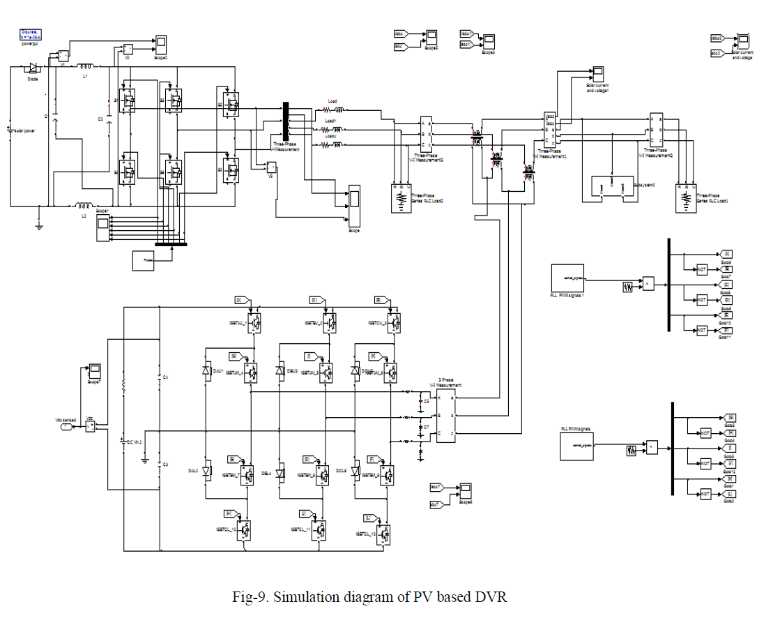 |
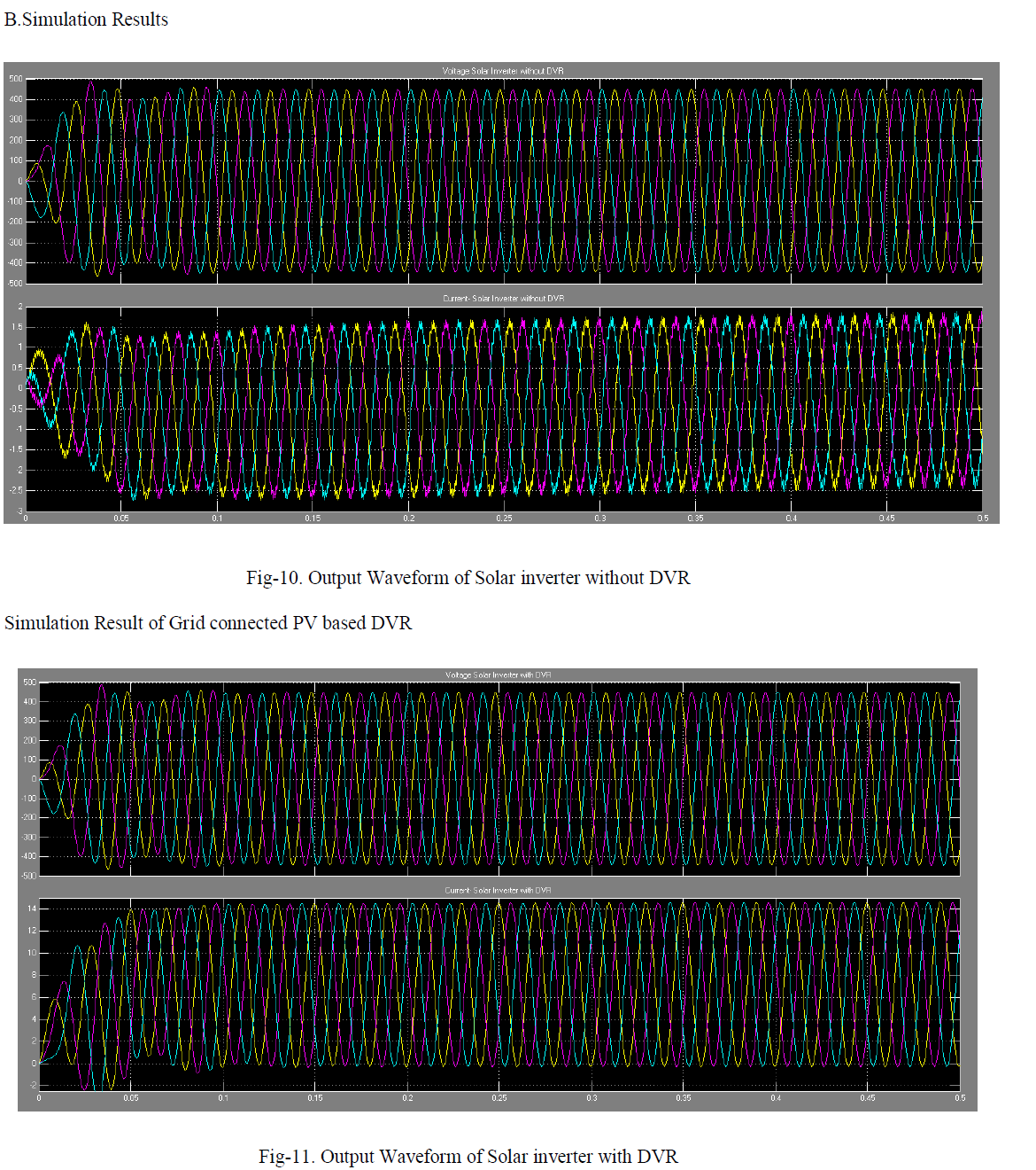
| The DVR is simulated to be in operation only when the supply voltage differs from its nominal value. It reduces the energy consumption from the utility grid. When the PV array generates more power than the load demand, the excess power is stored in the battery. Therefore, during the no injection period, the generated power in the PV array charges the batteries. During the night time, the output voltage of the PV array is too low. At that time, the batteries are charged by the supply. A programmable three phase voltage source is used to provide the single phase variable voltage at the source end. The output waveform of PV system without DVR shown if Fig.10 and the output waveform of Grid connected PV based DVR shown in Fig.11. |
 |
V. CONCLUSION |
| Hybrid systems are the right solution for a clean energy production and hybridizing solar and wind power sources provide a realistic form of power generation. In this proposed system, Grid Connected Photovoltaic/Wind turbine (GCPW) hybrid system can be used to supply continuous power to the loads. It is observed that the extraction of the maximum power from PV array is obtained using MPPT system. The MPPT algorithm has been implemented. The proposed system has been simulated in MATLAB-SIMULINK environment. |
References |
|