ISSN ONLINE(2319-8753)PRINT(2347-6710)
ISSN ONLINE(2319-8753)PRINT(2347-6710)
Deepak Kumar S Nadiger1, Meena Priya Dharshini2
|
| Related article at Pubmed, Scholar Google |
Visit for more related articles at International Journal of Innovative Research in Science, Engineering and Technology
Achieving high data rates in wireless transmission is in demand and has become a competitive factor in current fast moving world. Generally Multiple-Input-Multiple-Output systems are used to achieve high data rates. In MIMO every user may experience inter-user-interference because data of two or more users is transmitted from transmitter over a same channel. To mitigate this inter-user-interference a zero-force pre-coding is used at the transmitter, where data is coded and transmitted through channel (MIMO), so that data received at receiver has less Bit Error Rate (BER). Various efforts are made to simulate zero-force pre-coding algorithm for performance, in this work zero-force pre-coding technique with OFDM transmitter and receiver is implemented in HDL and this Zero-force precoded MIMO-OFDM system is simulated using Xilinx 13.4 and MATLAB R2013. BER is calculated for different values of SNR and this BER is compared with MIMO OFDM channel without pre-coding. More over this zero-force pre-coded MIMO OFDM system is synthesized for synthesis report.
Keywords |
| Multiple-input-multiple-output (MIMO) OFDM system, Zero-force pre-coding, Block Diagonalization, Singular value decomposition (SVD), Bit error rate (BER). . |
I. INTRODUCTION |
| In wireless communication achieving higher channel capacity by efficiently exploiting the transmission medium is a challenging task. Normally communication is carried out through TDMA and FDMA, Where single user data is transmitted through a channel at a time. In case of TDMA and FDMA maximum channel capacity (Data rate) for particular SNR is theoretically given by Shannon limit. |
| With evolution of 4G technologies and emergence of extremely high rate applications such as high-definition video conference, demands to achieve data rate above this Shannon limit. This demand to achieve high data rate becomes challenging and motivational factor for implementation of MIMO systems without inter-user–interference (IUI). To reduce Bit Error Rate (BER) in these MIMO systems due to IUI a proper pre-coding technique should be used which is less complex to implement. One of such technique is to use zero-force pre-coding at transmitter in MIMO system, which is less complex and simple compared to non-linear pre-coding techniques. |
| Zero force pre-coding is a linear pre-coding technique and it based on generalization of channel inversion for Multi– user systems, denoted as Block diagonalization. Block diagonalization is a matrix calculated based on singular value decomposition (SVD) operation, which depend on number of users and the dimensions of each user’s channel matrix. Paper is organized as follows. Section II gives the literature survey carried out to implement this zero-force pre-coded OFDM system. Section III explains the basic principle of zero-force pre-coding to reduce BER. Section IV provides the implementation details of zero-force pre-coded OFDM system. Section V presents simulated results and Device utilization summary of implementation. Finally, Section VI presents conclusion |
II. LITERATURE SURVEY |
| Multiple input/multiple output (MIMO) systems were described in the mid-to-late 1990s. MIMO offers higher data rates as well as spectral efficiency. So due to this advantage many standards have already incorporated MIMO. ITU uses MIMO in the High Speed Downlink Packet Access (HSPDA), part of the UMTS standard. MIMO is also part of the 802.11n standard used by wireless router as well as 802.16 for Mobile WiMax application used by cell phones. The LTE standard also incorporates MIMO |
| A single input single output (SISO) channel has one transmitter and one receive [1]. In SISO channel in order to increase the channel capacity it is required to increase the enormous amount of power. In MIMO systems the channel capacity increases linearly with number of transmitting and receiving of antennas. A MIMO system has number of transmitting and receiving antennas and this MIMO system is modeled by using channel matrix H. The matrix H of size (NR, NT) has NR rows, representing NR received signals, each of which is composed of NT components from NT transmitters. Each column of the H matrix represents the components arriving from one transmitter to NR receivers. The H matrix is called the channel information. Each of its entries is distortion coefficient acting on the transmitted signal amplitude and phase in time-domain. So if H is a channel matrix can be thought as a matrix channel. To find this channel matrix data is sent from one antenna and response is noted from all receivers .this procedure is repeated for all transmitting antennas to obtain all the elements of channel matrix. This channel matrix is a key parameter used in precoding technique to mitigate inter-symbol-interference |
| Different pre-coding techniques are been proposed to mitigate IUI [2]. These pre-coding techniques are classified as linear and non-linear pre-coding techniques. Nonlinear pre-coding technique includes successive minimum-meansquared error (SMMSE) and Tomlinson-Harashima pre-coding (THP). Linear pre-coding includes block diagonalization pre-coding and regularized block diagonalization pre-coding (RBD). Simulation results of all above mentioned pre-coding techniques [2] shows that RBD has less bit error rate and extracts full diversity of the system.RBD is based on generalization of block diagonalization (BD), which forms basis for zero-force pre-coding algorithm. More over these linear pre-coding techniques are less complex to implement when compared with non-linear types. |
| Zero-force pre-coding is a linear pre-coding technique and it is based on calculation of pre-coding matrix [3]. Optimal pre–coding matrix M is calculated such that all MUI is zero by choosing a pre–coding matrix Mj that lies in the null space of the other users’ channel matrices. Zero-Forcing (ZF) tries to enforce the complete nulling of the MUI. A MU– MIMO DL channel decomposed into multiple parallel independent SU- MIMO channels. The main idea behind the method relies on the computation of the BD matrix via Singular Value Decomposition (SVD) for these SU MIMO channels. |
| The main blocks necessary for Implementing [3] Zero-Forcing pre–coding algorithm are: construction of matrices taking vectors as input, extraction of columns from matrices, scalar and matrix multiplications, additions, data storage, SVD factorization. There are different choices for Implementing SVD such as Jocobi rotation and QR decomposition. In our project we use this CORDIC module to implement SVD since they are more accurate and computationally more efficient than Jacobi method |
III PRINCIPLE ZERO-FORCE PRE-CODING |
| Let [3] us consider a MU-MIMO transmission system that includes linear pre–processing performed at the transmitter let the transmitter has nT transmitting antennas. The received signal R at the receiver side can be defined as |
| R = CPd + n (1) |
| Where d is a data vector of arbitrary dimension nT ×m, P is the nT × m pre–coding matrix that has to be computed and n is the additive noise. |
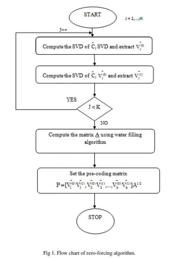
| The condition to for eliminating the multi-user interferences is that CiPj = 0 for i≠j. Then computation of the pre– coding matrix P becomes extremely important [3]. It is possible to find the optimal pre–coding matrix P such that all MUI is zero by choosing a pre–coding matrix Pj that lies in the null space of the other users’ channel matrices. In order to achieve such a goal, the channel matrix of each user, or its estimation, is needed. A MU–MIMO down Link channel is then decomposed into multiple parallel independent SU MIMO channels and the main idea behind the method relies on the computation of the Block Diagonalization matrix via a Singular Value Decomposition (SVD). Figure 1 shows the flowchart [3] of the ZF Algorithm. |
 |
IV IMPLEMENTATION OF PRE-CODED MIMO OFDM CHANNEL |
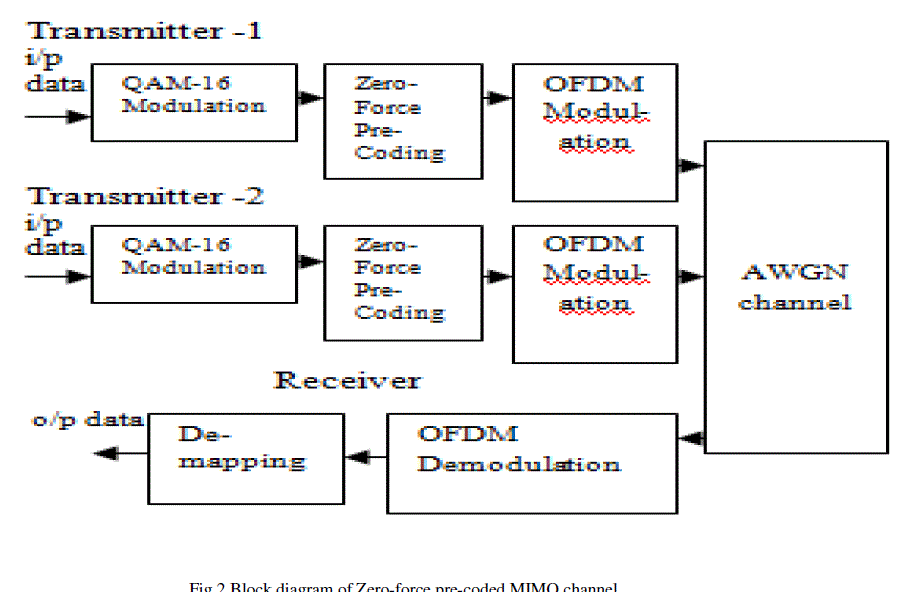
| Hardware implementation of zero-force pre-coded 2X2 MIMO OFDM system is as shown in Fig 2. The binary data is passed through QAM-16 modulator and the modulated data is pre-coded using zero-force pre-coding, then this precoded it is passed through OFDM system. Output of 2 transmitters (or 2 user data) is passed through Additive White Gaussian Noise (AWGN) channel (MATLAB is used to create channel part). Data is received at the receiver by OFDM demodulation and QAM-16 demodulation. BER is calculated for different values of SNR and it is compared with MIMO OFDM channel without pre-coding. |
| Transmitter and receiver including zero-force pre-coding is implemented using hardware description language (VHDL) and AWGN channel is implemented using MATLAB coding. |
 |
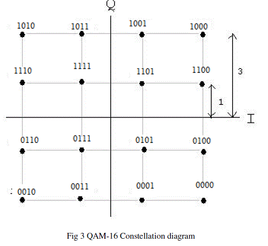
| To implement QAM-16 modulation constellation mapping is used as shown in Fig 3, and data is encoded accordingly. This modulated encoded data is of 16 bit width and it passed through IFFT block then and to zero-force pre-coder. Demapping or QAM-16 demodulation used in receiver part is reverse process of constellation mapping. |
 |
| OFDM modulation [5] and demodulation are implemented using IFFT and FFT blocks respectively. Fig 4&5 shows the block diagram to implement OFDM modulator and demodulator respectively |
 |
| a. The input to symbol generator is the output of zero-force pre-coder a symbol generator will produce 4 symbols (values) based on incoming data. |
| b. Zero padding block pads 4 zeros for the values generated by symbol generator so that the FFT block can have 8 inputs to perform 8-bit IFFT |
| c. An 8-point IFFT is performed on the data coming from zero padding blocks giving 128 values. Taking IFFT is equivalent to adding pilots or subcarrier because adding different orthogonal sinusoidal signals which are nothing but inverse Fourier transform. |
| d. To mitigate the effect of dispersive channel distortion in high data rate OFDM systems, cyclic prefix is introduced to eliminate inter-symbol interference (ISI). It copies the end section of an IFFT packet to the beginning of an OFDM symbol. |
| OFDM demodulation is the reverse process of OFDM modulation which includes inverse cyclic prefix, FFT, inverse zero padding and De-mapping. Here we use 128 point FFT to demodulate the data. De-mapping is nothing but a QAM demodulation |
 |
V .RESULTS |
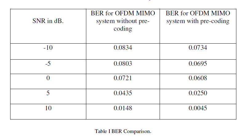
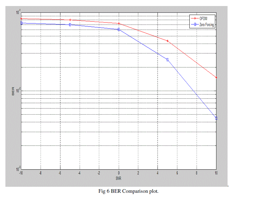
| In our work OFDM transmitter including zero-force pre-coder and OFDM receiver is implemented in HDL . Channel part is created using MATLAB coding, hence simulation to calculate BER is Performed using two software tools modelsim 6.3f (Xilinx is used for coding) and MATLAB R2013. Intermediate data from one software tool is saved in text file and given as input to another software tool. BER is compared between zero-force pre-coded OFDM MIMO system and OFDM system without pre-coding. The comparison table and plot is as shown below. |
 |
| BER Comparison plot is as shown in figure 6 |
 |
| Synthesis (device utilization summary) result for a Zero-force pre-coded OFDM transmitter and receiver is shown is shown in table below. |
| Selected Device: 4vlx15sf363-12 |
| Speed Grade: -12 |
 |
VI. CONCLUSION |
| In this work, a zero-force pre-coded OFDM MIMO system is implementing in HDL (VHDL) by surveying various implementation techniques for each block. A channel is created in MATLAB and the implemented system is simulated to calculate BER. BER is calculated for different values of SNR and it is compared with OFDM MIMO system without pre-coding. Simulation results show that the bit error rate is reduced in zero-force pre-coded OFDM MIMO system. The implemented design is synthesized for synthesis report. |