ISSN ONLINE(2319-8753)PRINT(2347-6710)
ISSN ONLINE(2319-8753)PRINT(2347-6710)
Mr. S. Arul Murugan1, Mr. A. Anbarasan., M.E., (Ph.D.) 2
|
| Related article at Pubmed, Scholar Google |
Visit for more related articles at International Journal of Innovative Research in Science, Engineering and Technology
In this project, a simple single phase gridconnected photovoltaic (PV) inverter topology was implemented, this topology will not inject any lower order harmonics into the grid due to high-frequency pulse width modulation operation. The novel design of inverter that mitigates the lower order harmonics is presented in this project. A proportional-integral (PI) controller are implemented in order to overcome the lower order harmonic distortions. Low total harmonic distortion less than 5% have been achieved. The complete design has been validated with MATLAB software and the overall system operation is observed
Index Terms |
| filters, inverters, PI controller |
INTRODUCTION |
| Renewable sources of energy such as solar, wind, and geothermal have gained popularity due to the depletion of conventional energy sources. Hence, many distributed generation (DG) systems making use of the renewable energy sources are being designed and connected to a grid. How power quality are affected and in what way it can be reduced are seen in this chapter. |
DISTRIBUTED GENERTION |
| In this project, one such DG system with solar energy as the source is considered. Single-phase grid tied inverter is one among types of inverters widely used in photovoltaic (PV) generation system due to the advantages they offer. Application of PV as a source of electrical energy showed a tendency to increase in terms of generation capacity and in terms of its spread in large areas around the world. Many aspects trigger the trend; economic, technology and policy are some among many. The restricted reserve of fossil fuel sources and followed by the increasing cost of fossil fuel based electricity generation has motivated the effort to exploit other alternative energy sources. |
| In the other hand, the high price of equipment and system of photovoltaic generation as the main constraint on implementing this renewable generation system shows significant reduction during recent years; implicates to declination of production cost per kW electric from photovoltaic. The maturity and continuously improved technology implemented on photovoltaic generation system that causes the photovoltaic power conversion more efficient, the typical advantages of PV generation compared with other electrical generation systems of renewable energy sources such as its flexibility and simplicity to build in any places, their dependency from transportation system are some technical factors causes the change to this type of renewable energy generation for electricity is preferred. |
| HARMONICS |
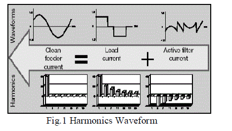
| Harmonic is a non-sinusoidal component present in a complex wave having a frequency of integral multiples of the fundamental frequency. A complex wave form can be mathematically resolved using Fourier series as a sum of a sequence of sinusoids such as f0 + 2f0 +3f0 +4f0+5f0+6f0+7f0+…where f0 is called the fundamental, multiples of f0 are the harmonics. The basic harmonics waveforms are shown |
 |
| ORIGIN OF LOWER ORDER HARMONICS |
| The dominant causes for the lower order odd harmonics are the distorted magnetizing current drawn by the transformer, the inverter dead time, and the semiconductor device voltage drops. Other factors are the distortion in the grid voltage itself and the voltage ripple in the dc bus. The dead-time effect introduces lower order harmonics which are proportional to the dead time, switching frequency, and the dc link voltage. The dead-time effect for each leg of the inverter can be modeled as a square wave error voltage out of phase with the current at the pole of the leg. The device drops also will cause a similar effect but the resulting amount of distortion is smaller compared to that due to the dead time. Thus, for a single-phase inverter topology considered, net error voltage is the voltage between the poles and is out of phase with the primary current of the transformer. |
| EFFECTS OF HARMONICS |
| The detrimental effects of harmonic distortion can be manifested in many different ways, like as following. |
| 1. Increased heating effect on electrical distribution equipment and cables, |
| 2. Large neutral currents, |
| 3. Malfunction of protective devices like relays, |
| 4. overheating of transformers, |
| 5. Excessive voltage drops, |
| 6. Bus bar overloading, |
| 7. Losses in switching devices, etc |
| HARMONICS FILTERS |
| Harmonic filters isolate harmonic current to protect electrical equipment from damage due to harmonic voltage distortion. They can also be used to improve power factor. Harmonic filters require careful application to ensure their compatibility with the power system in present and future nonlinear loads. Harmonic filters tend to be relatively large and can be expensive. Harmonic Filter types include: |
| 1. Passive filters |
| 2. Active filter |
| PASSIVE FILTERS |
| Passive harmonic filters are built with a series of passive components such as resistors, inductors and capacitors. Passive filters are most common and available for all voltage levels. They are built by combinations of capacitors, inductors (reactors) and resistors. Often, passive filters cannot provide optimal harmonic current reduction without unwanted side effects such as ringing transient response, unwanted resonances, and overcompensation. Diode-rectifier loads, typical of computer power supplies, often require very little 50 Hz power factor correction capacitance relative to the level of harmonic currents generated. As such, it is extremely difficult to provide a passive harmonic filter that does not overcompensate at 50 Hz, causing a leading displacement power factor. |
| Passive filters for harmonic reduction provide low impedance paths for current harmonics. Thus, the current harmonics flow into the shunt filters instead of back to supply. The passive filter consists of series LC filters tuned for specific harmonics, normally combined with a high pass filter used to eliminate the rest of the higher-order current harmonics. The drawbacks with passive filters are that they are strongly dependent on the system impedance, which depends on the distribution network configuration and the loads. |
ACTIVE FILTERS |
| Active filters are those which consist of active components like Thyristors, IGBTs, MOSFETs, etc. Active filtering techniques have drawn great attention in recent years. Active filters are mainly for the purpose of compensating the transient and harmonic components of load current iL so that, only fundamental components remain in the grid current. Active filters are available mainly for low voltage networks. The active filter uses power electronic switching to generate harmonic currents that cancel the harmonic currents from a nonlinear load. By sensing the nonlinear load harmonic voltages and/or currents, active filters use either. |
PROPOSED SYSTEM |
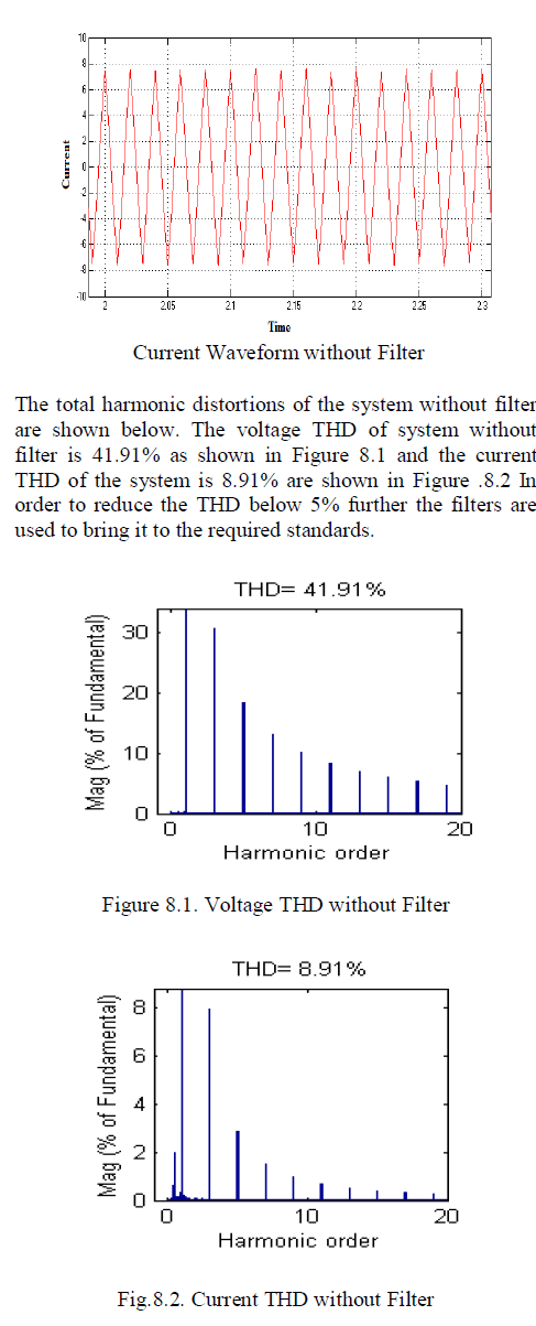
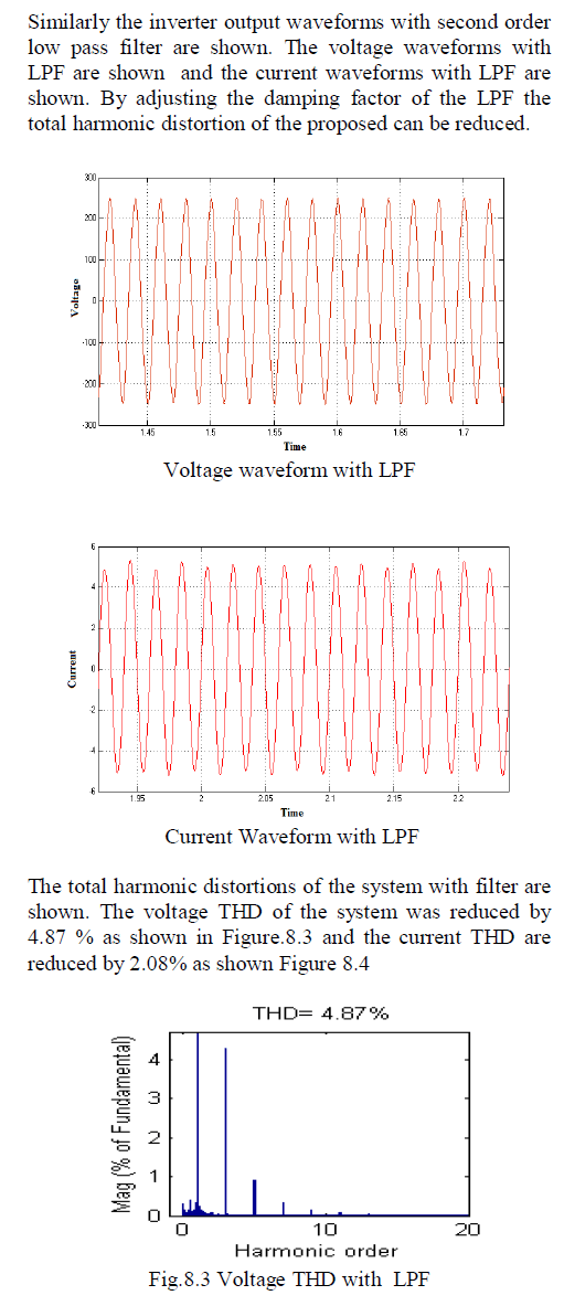
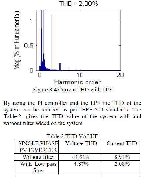
| In this paper a single phase grid connected PV (Photovoltaic) inverter system are considered, the main objective of the system is to reduce the lower order harmonics that are induced on the inverter due to dead time of inverter and transformer core-saturation. These lower order harmonics will make switching losses and reduce the efficiency of system, the higher order harmonics cannot affect the system largely and it can be eliminated by using passive or active filters. The proposed system consists of PI (Proportional & Integrator) controller with a passive filters and second order low pass filter are used to reduce the lower order harmonics |
| ADVANTAGES |
| 1. The switches are all rated for low voltage which reduces the cost |
| 2. Lesser component count in the system improves the overall reliability. |
| 3. It will be a good choice for low-rated PV inverters of rating less than a kilowatt. |
| 4. The cost of the system is very low. The THD of the system will be less than 5%. |
| GRID CONNECTED SINGLE PHASE PV INVERTER |
| The grid-connected single phase photovoltaic(PV) inverter consisting of a boost section, a low-voltage single-phase inverter with an inductive filter, and an isolation transformer interfacing with the grid is considered. Ideally, this topology will not inject any lower order harmonics into the grid due to high-frequency pulse width modulation operation. A proportional-integral (PI) controller are implemented to reduce the lower order harmonics |
| BLOCK DIAGRAM |
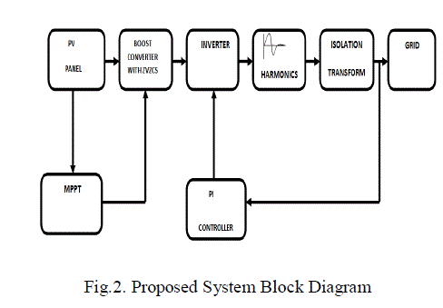
| The topology of the solar inverter system is simple. It consists of the following stages as shown in Figure.2. |
| 1. A PV module with Maximum Power Point Tracking (MPPT). |
| 2. A boost converter stage to perform (DC-DC converter). |
| 3. A low-voltage single-phase H-bridge inverter. An isolation transformer for interfacing with the grid. |
 |
| PHOTOVOLTAIC GENERATION SYSTEM |
| To analyze the power quality behaviors resulted from operation of a PV (Photovoltaic) plant in distributed generation system, a review of the PV generation system and some aspects that involved in their operation as the part of the system must be done, they are: the PV module, PV inverter and the module-inverter configuration, the PV plant-grid interaction and the atmospheric condition. The main components of a PV generation plant are the PV modules and the PV inverters. The PV module is used as energy conversion equipment, converting the light energy to electrical form of the dc voltage and current. The conversion involves interaction process of the light, thermal and electrical parameters in a photovoltaic material. The PV inverter is then used to convert the dc to ac power to be used by consumer or to be connected to the grid. |
| PHOTOVOLTAIC MODULE |
| Photovoltaic module is set up from formation of photovoltaic cells that convert the energy in the light to electric power. The modules are then arranged in both series and parallel configuration as a photovoltaic array to reach the voltage and current requirement. Photovoltaic cells are semiconductor devices that draws non-linear characteristics between output current (I) and voltage (V) on their terminal. In a condition when the light shapes their surface, the light generations current are produced in proportional to the light intensity, in the same time a dc voltage is generated. If the generated voltage is high enough, the solar cell current drops extremely, similar to the behavior of the diode as seen on the knee point of the diode’s characteristic. From these behaviors, based on circuit perspective, photovoltaic cell can be modeled as configuration of current sources in parallel with some diodes, serial and parallel resistors are then added to present the voltage and current losses during cell operation. A photovoltaic cells model called the single diode model is widely used as shown in Figure.3 |
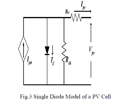 |
| Ipv and Vpv are the current and voltage of the PV cell. Iph is the light generating current, its value depends on irradiance and the physical dimension of photovoltaic cell, Io is the diode dark saturation current. This single diode model of PV cell can be described using the follows mathematical model to form the cells |
| The Boltzmann constant = 1.3807 x 10⁻²³ JK-1 and electric charge = 1.6022 x 10⁻¹⁹ C are presented by k and q. Rse and Rsh are the representation of the parasitic series and shunt resistances that associated with real solar cells in operation condition. A0 is the diode ideality (quality) factor; its value is taken between 1 and 2, A0 = 1 indicates that diode behavior of cell is dominated by recombination in the quasi-neutral regions and A0 = 2 indicates that recombination in the depletion region dominates. ISCR is short circuit current of the cell on 1000 W/m2 and 25 OC of temperature. K1 is the short circuit temperature coefficient at ISCR. T and Ga are cell temperature and irradiance on cell surface. I0r is the cell saturation current at reference temperature Tr. EGO is band gap energy. |
| MAXIMUM POWER POINT TRACKING |
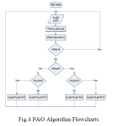
| The efficiency of a PV plant is affected mainly by three factors: the efficiency of the PV panel (in commercial PV panels it is between 8-15%, the efficiency of the inverter 95-98 % and the efficiency of the maximum power point tracking (MPPT) algorithm (which is over 98%. Improving the efficiency of the PV panel and the inverter is not easy as it depends on the technology available, it may require better components, which can increase drastically the cost of the installation. MPPT algorithms are necessary because PV arrays have a nonlinear voltage-current characteristic with a unique point where the power produced is maximum. The various methods are used for improving the efficiency of MPPT algorithm, for these P&O (Perturb & Observe) used. |
| The Perturbation and Observation algorithm is broadly used due to it is simple and easy to construct. According to the flowchart illustrated in Figure 4.P&O method basically increases or decreases (the perturbation stage) the controller reference voltage by a step size noted as C, hence the PV source terminal voltage, and subsequently estimates the power difference between the present PV power and that before the perturbation (observation stage). If a positive PV power difference is obtained that means the PV power is increased and the tracking is in the right direction, the perturbation direction will be carried on (increase or decrease). On the contrary if power difference is negative, a power reduction is caused due to the perturbation, so the direction of perturbation should be reversed. |
 |
| As a result of continuous perturbation, P&O algorithm may not stop at the desired MPP voltage but oscillates around it, causing PV power loss. One way to minimize the tracking oscillation is to reduce the perturbation voltage step. As a consequence of that, in the constant irradiance state the PV power curve will be smooth with very small ripples. However, the tracking speed will detract causing more power lose and losing the ability to track certainly at the rapid atmospheric changes. Even though choosing a large perturbation step will result in achieving fast tracking response at the suddenly atmospheric changes, in the steady state the mentioned oscillation will be quite considerable. |
| BOOST CONVERTER STAGE |
| A boost converter (step-up converter) is a DC-to-DC power converter with an output voltage greater than its input voltage. It is a class of switched-mode power supply (SMPS) containing at least two semiconductor switches (a diode and a transistor) and at least one energy storage element, a capacitor, inductor, or the two in combination. Filters made of capacitors (sometimes in combination with inductors) are normally added to the output of the converter to reduce output voltage ripple. The switch is typically a MOSFET, IGBT, or BJT. |
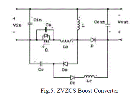 |
| Soft switching can mitigate some of the mechanisms of switching loss and possibly reduce the generation of EMI. Semiconductor devices are switched on or off at the zero crossing of their voltage and current waveforms. For this project a ZVZCS methods are adopted as shown in Fig.5. The zero-voltage zero-current switching (ZVZCS) PWM converters are derived from the full-bridge phase-shifted zero-voltage (FB-PS-ZVS) PWM converters. |
| H-BRIDGE CONFIGURATION |
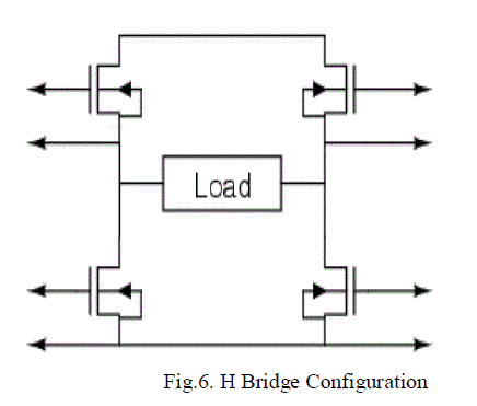
| An H-bridge or full bridge converter is a switching configuration composed of four switches in an arrangement that resembles an H. By controlling different switches in the bridge, a positive, negative, or zeropotential voltage can be placed across a load. When this load is a motor, these states correspond to forward, reverse, and off. The use of an H-bridge configuration to drive a load is shown in Fig.6. The H-bridge circuit consists of four switches corresponding to high side left, high side right, low side left, and low side right. There are four possible switch positions that can be used to obtain voltages across the load. These positions are outlined in Table .1. The harmonic table for switched mode inverter are also shown in appendix (B). |
 |
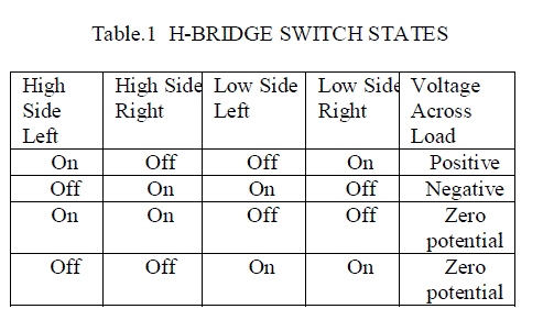 |
| Note that all other possibilities are omitted, as they would short circuit power to ground, potentially causing damage to the device or rapidly depleting the power supply. The switches used to implement an H-bridge can be mechanical or built from solid state transistors. Selection of the proper switches varies greatly. The use of P-channel MOSFETs on the high side and N-channel MOSFETs on the low side is easier, but using all N-channel MOSFETs and a FET driver, lower “on” resistance can be obtained resulting in reduced power loss. The use of all N-channel MOSFETs requires a driver, since in order to turn on a high side Nchannel MOSFET, there must be a voltage higher than the switching voltage. This difficulty is often overcome by driver circuits capable of charging an external capacitor to create additional potential. |
| ISOLATION TRANSFORMER |
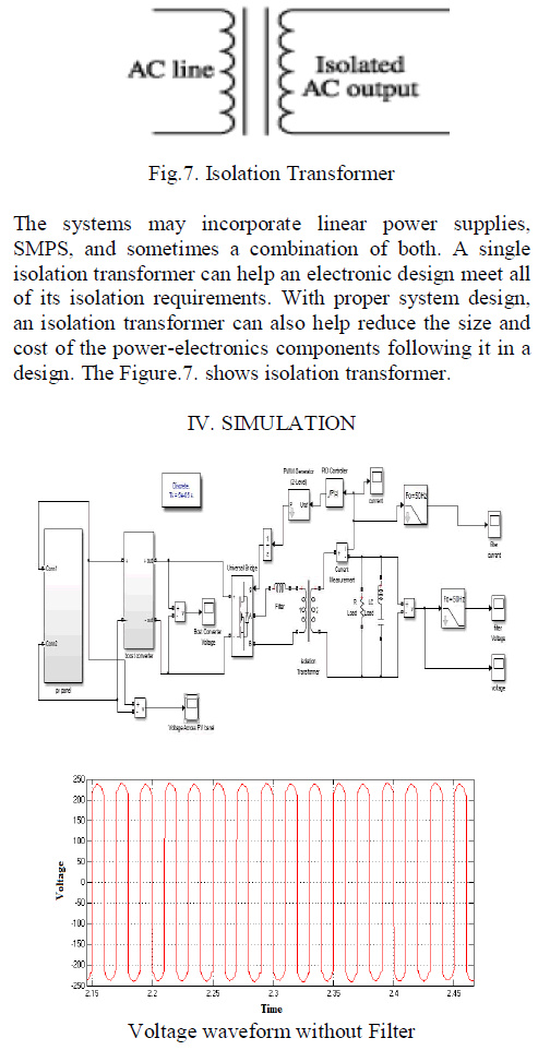
| Isolation transformers offer an effective means of meeting the requirements of domestic and international safety standards for electronic equipment. In the United States, for example, such standards are set by the Occupational Safety and Health Administration (OSHA), with product testing performed according to appointed laboratories, such as Underwriters Laboratories (UL). Throughout Europe, safety standards are established by the International Electro technical Commission (IEC), with testing performed by the laboratories of individual member nations, such as the Verband Deutscher Electro techniker (VDE) in Germany. Isolation transformers enable a variety of electronic systems to meet safety requirements. Such systems include medical diagnostic equipment, computer systems, and telecommunications equipment. |
 |
 |
 |
 |
CONCLUSION |
| A grid connected single phase PV inverter has been proposed,for ensuring high quality of the current injected to the grid. The PI controller was implemented to reduce the dead time of inverter and lower order harmonics. By using MATLAB simulation it was observed that the overall THD value of the PV system is reduced less than 5% |
References |
|