ISSN ONLINE(2278-8875) PRINT (2320-3765)
ISSN ONLINE(2278-8875) PRINT (2320-3765)
K. Lenin Ram1 and Dr. R.P. Kumudini Devi2
|
| Related article at Pubmed, Scholar Google |
Visit for more related articles at International Journal of Advanced Research in Electrical, Electronics and Instrumentation Engineering
This paper describes the Harmonics Suppression for Diesel Generator based Isolated Generation System using distribution static synchronous compensator (DSTATCOM). Here two control schemes for DSTATCOM are compared. PI controller and Fuzzy logic controller. PI controller is a hysteresis current controlled technique which is used to maintain a constant voltage at the dc-bus of a voltage-source converter (VSC) working as a DSTATCOM. Switching of VSC is achieved by controlling source currents to follow reference currents using hysteresis-based PWM control. The operation of the two DSTATCOM control schemes for reducing the harmonic contents at the source side of the DG set is compared using MATLAB/SIMULINK model. The modeling is performed for a three-phase, threewire star connected synchronous generator coupled to a diesel engine, along with the three-leg VSC working as a DSTATCOM. Results are presented to verify the effectiveness of the control of DSTATCOM for harmonics reduction and an optimal operation of the DG set.
Keywords |
| DSTACOM, PI controller, Fuzzy logic controller, harmonics |
INTRODUCTION |
| Installation of the diesel engine-based electricity generation unit (DG set) is a widely used practice to feed the power to some crucial equipment in remote areas. DG sets used for these purposes are loaded with linear as well as non linear loads. One of the major effects of power system harmonics is to increase the current in the system. This is particularly the case for the third harmonic, which causes a sharp increase in the zero sequence current, and therefore increases the current in the neutral conductor. Electric motors experience losses due to hysteresis and losses due to eddy currents set up in the iron core of the motor. These are proportional to the frequency of the current. Since the harmonics are at higher frequencies, they produce higher core losses in a motor than the power frequency would. This results in increased heating of the motor core, which (if excessive) can shorten the life of the motor.All of these factors lead to the increased fuel consumption and reduced life of the DG sets. These forces the DG sets to be operated with de-rating, which results into an increased cost of the system. The DSATCOM can provide compensation for harmonics which facilitates to load the DG set up to its full KVA rating. |
| The control of DSTATCOM with capabilities of reactive power compensation and harmonics is achieved by PI controller. This is used to extract positive-sequence fundamental frequency real component of the load current. The dcbus voltage of voltage source converter (VSC) is supported by a proportional–integral (PI) controller which computes current component to compensate losses in DSTATCOM. The other control technique which can be used to achieve this objective is using the Fuzzy logic controller. This proposed system is simulated under MATLAB environment using Simulink. |
SYSTEM CONFIGURATION |
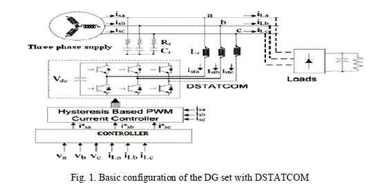 |
| Fig. 1 shows the configuration of the system for a three phase three-wire DG set feeding 3 phase full bridge diode rectifier non linear load. A 30 MW system is chosen to demonstrate the work of the system with the DSTATCOM. The DSTATCOM consists of an IGBT based three-phase three-leg VSC system. The load current is tracked using reference current generator, which in conjunction with the hysteresis-based PWM current controller that provides switching signals for VSC-based DSTATCOM. It controls source currents to follow a set of three-phase reference currents. The system specification is given in Table I. |
 |
SYSTEM OPERATION |
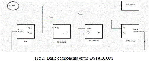 |
| The basic components of a typical DSTATCOM are as shown in Fig.2. The essential components are Voltage Source Inverter (VSI), Reference current generator, Hysteresis current controller and DC bus voltage controller. The various functions of the individual components are explained as follows. |
| a) Voltage Source Inverter (VSI) |
| The VSI block consists of an “Universal Bridge” block set in which the IGBT with anti-parallel diodes are configured in full bridge and the value of the DC-bus capacitor (Cdc) is calculated based on the r.m.s value of the source voltage, peak r.m.s value of the reactive and harmonic load currents, period of source voltage and maximum or minimum DC-bus voltage. |
| b) Reference current generator |
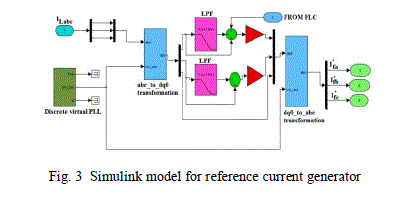 |
| The synchronous reference frame theory is employed to obtain compensation current reference signal, since it deals mainly with DC quantities and computation is instantaneous. The component diagram of synchronous reference frame theory model is shown in Fig.3. This control strategy uses “discrete PLL” block for generating sinusoidal reference currents, “a-b-c to d-q-0 transformation” block for Park’s transformation, and “d-q-0 to a-b-c transformation” block for Inverse Park’s transformation. Two second order digital low pass filter blocks are used for extracting fundamental component from load currents. The “a-b-c to d-q transformation block” converts three phase a-b-c-reference frame currents in to stationary d-q reference frame currents and applied to a “Discrete 2nd-Order LPF” block. The low frequency fundamental components obtained from LPF are subtracted from non filtered signal and added to current signal obtained from DC bus voltage controller to obtain compensation reference currents in d-q reference frame. By applying these currents to “d-q-0 to a-b-c transformation block” the compensation reference currents in a-b-c reference frame are obtained. |
| c) Hysteresis current controller |
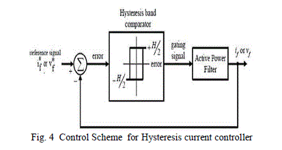 |
| The Hysteresis band Current Controller model is used for generating switching signals for the transistors of VSI, and is illustrated in Fig. 4.This current control technique imposes a PI type instantaneous control that forces the compensation current to follow its estimated reference. The actual compensation current is subtracted from its estimated reference. The resulting error is sent through a hysteresis controller to determine the appropriate gating signals. In this control scheme, a signal deviation (H) is imposed on if* to form the upper and lower limits of a hysteresis band. The if is then measured and compared with if * and the resulting error is subjected to a hysteresis controller to determine the gating signals when exceeds the upper or lower limits set by (estimated reference signal + H/2) or (estimated reference signal - H/2). As long as the error is within the hysteresis band, no switching action is taken. Switching occurs whenever the error hits the hysteresis band. The VSI is therefore switched in such a way that the peak-to-peak compensation current/voltage signal is limited to a specified band determined by H. The advantages of using the hysteresis current controller are its excellent dynamic performance and controllability of the peak-to-peak current ripple within a specified hysteresis band. |
| d) DC Bus Voltage Controller |
| The DC bus voltage is to be maintained at a constant value otherwise the source current will vary and lapse from sinusoidal waveform. Various types of controllers like Proportional-Integral (PI), adaptive, Neuro and Fuzzy Logic Controller (FLC) for DC bus voltage regulation are available. Here the Fuzzy Logic Controller (FLC) and Proportional- Integral (PI) have been chosen and the results were compared w.r.to harmonic reduction levels. |
| i) Fuzzy Logic Controller (FLC) |
| Since the fuzzy control rules are not derived from a heuristic knowledge of the system behaviour, neither precise mathematical model nor complex computations are needed and is based on human like linguistic terms in the form of IF-THEN rules to capture the non-linear system dynamics, FLC is adopted to control DC bus capacitor voltage. The Simulink model of the FLC is shown in Fig. 5. |
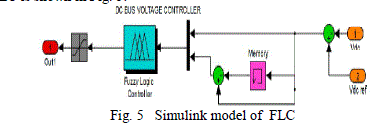 |
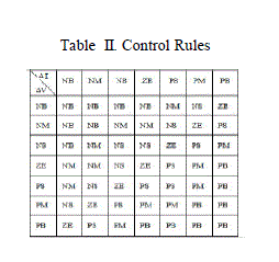
| The DC-bus voltage is first sensed and compared with DC reference voltage and error signal is generated. The error signal and its derivative are applied to fuzzy logic controller. Error signal is applied to “Memory” block and its output is subtracted from the error signal to obtain derivative of error signal. The two inputs and the output use seven triangular membership functions namely Negative Big (NB), Negative Medium (NM), Negative Small (NS), Zero (ZE), Positive Small (PS), Positive Medium (PM), Positive Big (PB). The type and number of membership functions (MFs) decides the computational efficiency of a FLC. The shape of fuzzy set affects how well a fuzzy system of If– then rules approximate a function. Triangles have been the most popular for approximating non-linear function because the parametric functional description of triangular membership function is most economic one. Hence the triangular MFs are chosen in this work. In this effort, the control rules for the STATCOM in Table II resulted from the understanding of STATCOM’s behaviour and experimental tests of its VSI’s performance. |
 |
| ii) PI Controller |
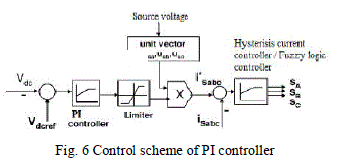 |
| It is implemented in the current control scheme. Actual current are detected by current sensors and are subtracted for obtaining a current error for a hysteresis based PI controller. Thus the ON/OFF switching signals for IGBTs of DSTATCOM are derived from hysteresis controller. |
SYSTEM PERFORMANCE |
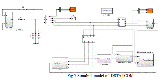
| The Simulink model of the DSTATCOM arrangement is shown in fig. 7. |
 |
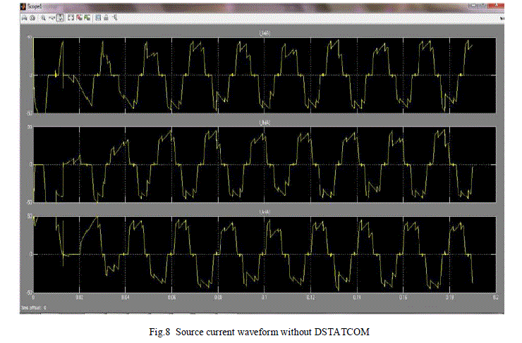
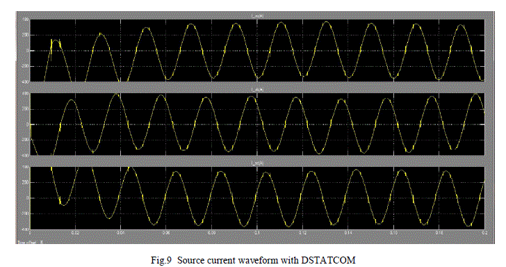
| The source current waveform simulated with and without DSTATCOM is shown in Fig.8 and Fig.9. |
 |
 |
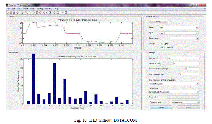
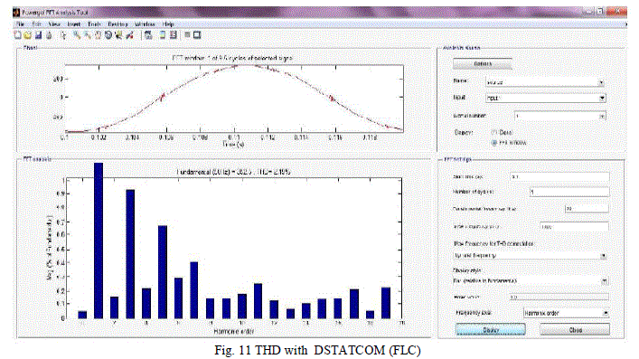
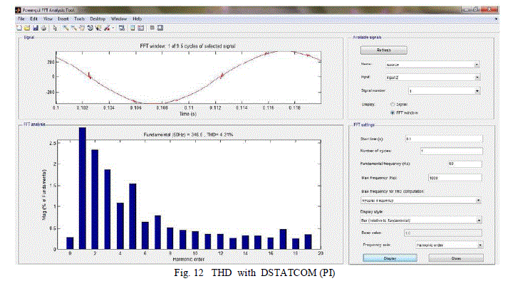
| The FFT analysis and THD values for various scenarios such as without DSTATCOM, with DSTATCOM using PI type controller and with DSTATCOM using FLC is depicted from Fig. 10 to Fig. 12. |
 |
 |
 |
RESULTS AND INTERPRETATION |
| The comparison of simulation results for reduction of harmonics using PI type controller and FLC is shown table III. It is observed that the effectiveness for reducing the harmonics due to non linear load is comparatively more for FLC controller than the PI type controller. The fuzzy logic controller is simpler and has faster response. Also the dynamic performance of the FLC is more superior than the PI controller. |
 |
References |
|