ISSN ONLINE(2278-8875) PRINT (2320-3765)
ISSN ONLINE(2278-8875) PRINT (2320-3765)
Deepti.K.Dinesan1 and Dr.S.Muthukumaran2
|
| Related article at Pubmed, Scholar Google |
Visit for more related articles at International Journal of Advanced Research in Electrical, Electronics and Instrumentation Engineering
In distribution power systems, voltage sag mostly results in financial losses and power quality issues. Power quality improvement can be achieved by conventional Dynamic Voltage Restorers (DVRs), which use bulky as well as costly power frequency transformers. These cause power losses and voltage drop. A High Frequency Link Dynamic Voltage Restorer (HFL-DVR) with fuzzy logic controller is proposed in this paper. The main features of HFL –DVR include relatively low losses, small size and low cost. The number of energy storage devices required is also less. The use of High Frequency Isolation Transformer helps to reduce the voltage rating of battery and also provides galvanic isolation with electrical safety. A fuzzy logic controller is added for obtaining acceptable properties, by reducing the effect of disturbances on the DVR output for both voltage sag and swell conditions.
Keywords |
| Fuzzy logic controller, High-frequency-link dynamic voltage restorer (HFL-DVR), High Frequency Isolation Transformer (HFIT), Voltage sag, Voltage swells. |
INTRODUCTION |
| Recently, power quality problems have become a major issue of concern for electricity consumers. The advent of a large numbers of sophisticated electrical and electronic equipments, such as computers, programmable logic, electrical drives etc., has resulted in power quality problems like voltage sag, voltage swell and harmonic distortion [1]. In distribution power systems, voltage disturbances mostly result in main financial losses and power quality issues [2], [3]. Custom power is a strategy which is used to help improve the power requirement of industrial and commercial consumers. The concept of custom power device is the application of power electronic control devices into power distribution system to supply quality power demanded by sensitive users. In power distribution networks, Dynamic Voltage Restorer (DVR) has become one of the most efficient and effective modern custom power device installed for sensitive loads. It is connected to the load through a series transformer and injects series voltage to compensate voltage disturbances through the transformer, by a voltage-source converter connected to dc link. |
RELATED WORK |
| In recent years, Dynamic Voltage Restorers have shown improvement in providing a better economic solution for Low- Voltage (LV) systems [4], due to significant improvement in insulated gate bipolar transistors, and also the size and cost of the converters in DVR structures have been reduced [5], [6]. Transformerless DVRs have been proposed, in order to reduce the size and cost of DVRs in LV systems [7]. By this approach, the number of switches and isolated capacitors required for each phase in a three phase system is increased. The charging circuitry for each phase is needed to be implemented. Series transformer effective usage is obtained [8]. To protect large sensitive loads from voltage sags, DVR at Medium Voltage (MV) level has been implemented [9]. The control of DVR with Sliding Mode Control (SMC) method makes it multi-purpose for the compensation of the voltage sag, swell, flicker and harmonics and uses minimum energy injection concept for restoration during DVR compensation. |
| The analysis and design of a three phase four wire Dynamic Voltage Restorer (DVR) based on supercapacitor as energy storage for power quality improvement has been proposed in electrical distribution system [10]. This system is capable of mitigating voltage disturbances at LV distribution system. The implementation of supercapacitor as an energy storage is to supply real power to the inverter during disturbances. A multilevel DVR of cascaded type is proposed which is able to connect to the grid without a transformer [11]. It can support an extended sag duration compared to two-level DVR. However, this cannot meet the requirements of low voltage application, where small- size, low- weight and low – cost systems are needed. An interphase ac–ac topology for single-phase sag compensation is cost efficient and has small size, since no storage device is present [12]. However, symmetrical voltage sags cannot be compensated by it. The single phase High- frequency- link DVR system has been proposed [13], [14]. When transformer is incorporated into a converter, substantial improvement is obtained such as reduction in size and weight. However, it is not possible to control the output of each phase independently, as one inverter supplies all the phases. The performance of DVR has been related to the adopted configuration and control strategy used for inverters. An asymmetrical voltagesource inverter controlled with fuzzy logic method based on hysteresis controller has been used to improve the operation of DVR to compensate voltage sag/swell [15]. A three phase high-frequency-link dynamic voltage restorer (HFL-DVR) has been implemented [16]. Various transfer functions are obtained for the circuit and the effect of PID controller and feedback loop is analysed on the behaviour of HFL- DVR. However it uses conventional control techniques and compensates only voltage sag conditions to improve power quality of distribution system. |
| In this paper, an improved structure is proposed based on high-frequency-link dynamic voltage restorer (HFL-DVR) with Fuzzy logic controller. It has reduced number of switches and provides independent operation condition for each phase. The operation condition is enhanced and also provides savings in size and weight. By the use of High frequency link transformer, the voltage level can be increased from an LV battery and also electrical safety can be obtained with galvanic isolation. Fuzzy logic controller is used to improve power quality of distribution system by mitigating the voltage sag and swell of sensitive load. |
PROPOSED HFL-DVR TOPOLOGY |
| PID controller is very common in the control of Dynamic Voltage Restorers. However, one of the disadvantages of these controllers is their inability to work under a wide range of operating conditions. So, Fuzzy logic controller can be proposed as a solution to this problem. This work proposes High Frequency Link- Dynamic Voltage Restorer (HFLDVR) with Fuzzy logic controller to improve power quality by reducing the voltage sag and swell of sensitive load. This device with proposed fuzzy logic control is connected in series with the distribution feeder. The block diagram for HFL-DVR with fuzzy logic controller is shown in Fig.1. |
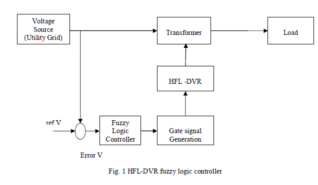 |
| The various components in the block diagram are as follows: |
| A. VOLTAGE SOURCE |
| Here Voltage source is the utility grid of 230V, 50HZ ac supply. The voltage sag or swell condition is created by either decreasing or increasing the applied ac supply voltage. |
| B. HFL-DVR |
| Independent operation condition is provided by the structure of High-Frequency-Link Dynamic Voltage Restorer (HFL- DVR), for each phase and also the number of switches is reduced. Hence, the operation condition is improved with significant savings in size and weight. It does not require separate energy storage systems for each phase compared to transformerless DVR topologies. Thus maintenance requirements are also reduced. By the use of High Frequency Isolation Transformer (HFIT), the voltage level can be increased from an LV battery to a High frequency link transformer, thereby providing galvanic isolation and electrical safety. |
| 1. COMPONENTS OF HFL- DVR: |
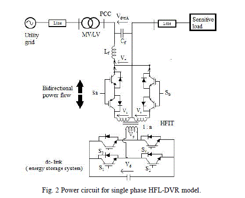
| The power circuit of HFL-DVR contains four main parts as shown in Fig.2: |
| (i) Voltage source full bridge Inverter (VSFBI) |
| (ii) High-frequency-isolating transformer (HFIT) |
| (iii) Bidirectional Cycloconverter (BC) |
| (iv) Output filter. |
| The first part of HFL- DVR is a Voltage Source Full Bridge Inverter (VSFBI) with four switches, i.e., S1 to S4 and a dc storage system (battery). The second part is a center-taped secondary winding High-Frequency-Isolating Transformer (HFIT). The third part is a Bidirectional Cycloconverter (BC) at the secondary side of HFIT, which contains the switches Sa and Sb. The last part is the output filter, consisting of Cf and Lf which is designed to remove high-frequency components of the Bidirectional Cycloconverter output voltage, Vc and form the output voltage, Vdvr. This voltage regulates the load voltage, while point of common coupling (PCC) voltage has been dropped. |
 |
| In this DVR, the number of switches and their associated control circuits have been reduced. HFL-DVR has been found to be appropriate for the protection of computers in computer centers, medical equipments and emergency equipments in hospitals where the dimensions of the circuit is essential. |
| 2. OPERATIONAL WAVEFORMS FOR HFL-DVR |
| There are 2 modes of operation for the proposed HFL- DVR. It is assumed that in the first operation mode, the DVR output voltage is positive and negative in the second mode. Both operation modes for a typical switching period are given in Fig.3. During one switching period, there are four intervals in each operation mode. |
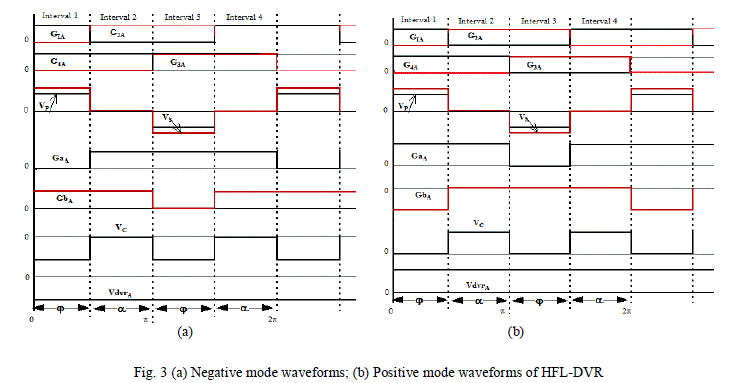 |
| The pulse gate of switches of VSFBI (i.e., G1A, G2A, G3A, and G4A) and BC (i.e., GaA and GbA), and the primary voltage VP, secondary voltage VS, output voltage of BC VC, and the output voltage of DVR VdvrA are depicted. The amplitude of the output voltage is adjusted according to the reference voltage by shifting the phase α of the leading-leg switches, i.e., S3A and S4A with respect to master-leg switches, i.e., S1A and S2A. The overlapping period of switches S1A and S4A or S2A and S3A is indicated by the width of Φ. So, as Φ increases, the width of Vp, and hence the width of VS, increases as well. The BC determines the sign of its output voltage VC. |
| So, the Bidirectional Cycloconverter chooses the pulses of Vs, in order to provide positive [Fig. 3(a)] or negative [Fig. 3(b)] voltage polarity at the output of DVR. Thus, VC is forced to track the reference voltage. At least one of the switches of SaA and SbA conducts or both may conduct simultaneously, during one switching period, to provide a path for Lf current avoiding high stresses at switching instants. Also, the switches turn ON/OFF, while the voltage of HFIT is equal to zero. The leakage inductance of HFIT must be minimized as much as possible. Hence snubber circuits could be used to damp the stored energy in the leakage inductance of HFIT. Finally, the output filter provides an output voltage Vdvr with a smooth waveform. |
| C. FUZZY LOGIC CONTROLLER |
| Fuzzy logic theory is considered as a mathematical approach to replicate the human approach in reaching the solution of a specific problem. It combines multi-valued logic, artificial intelligence and probability theory by using approximate reasoning to relate different data sets and to make decisions. In the field of control theory, the performance of Fuzzy Logic Controllers is well established. The schematic representation of fuzzy logic controller is given in Fig.4. |
| It provides robustness to dynamic system parameter variations as well as improved transient and steady state performances. The fuzzy logic based control scheme can be divided into four main parts namely, Knowledge base, Fuzzification, Inference mechanism and Defuzzification. The knowledge base consists of mainly data base and rule base. Data base has input and output membership functions which provide information for appropriate fuzzification and defuzzification operations. |
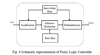 |
| The rule-base comprises a set of linguistic rules which relates the fuzzified input variables to the desired control actions. Fuzzification helps to convert crisp input signals, error (e) and change in error (ce) to fuzzified signals that could be identified by the level of memberships in the fuzzy sets. The inference mechanism converts the input conditions to fuzzified output using the collection of linguistic rules. Finally, the defuzzification converts the fuzzified outputs to crisp control signals. |
| D. SENSITIVE LOAD |
| Sensitive loads are causes for the deterioration in power quality. A nonlinear load is used in the load side of the system. Nonlinear loads are loads where the current is not proportional to the voltage. Foremost among loads meeting their definition is gas discharge lighting having saturated ballast coils and thyristor controlled loads. Non-linear loads generate harmonics in current waveform. The distortion of the current waveform leads to distortion of the voltage waveform. Switching on of a large induction motor can cause a large inrush current to flow in that circuit causing voltage dip in other parts of the system. Some of the main sensitive loads include-Transformer, capacitor banks; Power electronic loads such as uninterrupted power supply (UPS), Adjustable speed drives (ASD), Converters; Arc furnaces and induction heating systems etc. |
| E. GATE SIGNAL VOLTAGE GENERATION |
| The inverter circuit in DVR is responsible for generation of the compensating voltage. Hence the control of the inverter will directly affect the performance of the DVR. The inverter used in the proposed DVR is a three phase six pulse inverter. Mostly Insulated Gate Bipolar Transistors (IGBT) is chosen in the inverter circuit for their fast response and robust operation. For controlling modulation index, the inverter uses Sinusoidal Pulse Width Modulation (SPWM) and hence controlling the output voltage of the inverter. In SPWM, a sinusoidal reference signal of supply frequency (i.e. 50 Hz) is compared with a high frequency triangular carrier waveform (i.e. 1080 Hz for this work). |
| When the sinusoidal reference signal is greater than the triangular carrier wave, a batch of three IGBT switches out of the six are turned on and the counter switches are turned off and when the reference sinusoidal signal is smaller than the triangular carrier waveform in magnitude then the second batch of three IGBT switches are turned on and the first batch of switches are turned off. The magnitude of the sinusoidal reference signal determines the modulation index of the PWM signal generator which is dependent upon the error signal. The magnitude of the sinusoidal reference signal is controlled by the fuzzy logic based feedback controller which adjusts the magnitude according to the error magnitude and hence control the modulation index. |
MATLAB SIMULATION AND RESULTS |
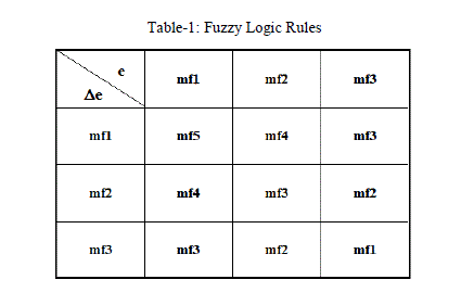
| In this work, a fuzzy logic based feedback controller is employed for controlling the voltage injection of the proposed Dynamic Voltage Restorer (DVR). The aim of the control system is to maintain voltage magnitude at the point where a sensitive load is connected, under system disturbances.The rules for fuzzy logic controller is given in table.1. Fuzzy logic controller is preferred over the conventional PI and PID controller because of its robustness to system parameter variations during operation and its simplicity of implementation. The control system of the general configuration typically consists of a voltage correction method which determines the reference voltage that should be injected by DVR and the VSFBI control which in this work is Fuzzy controller. |
 |
 |
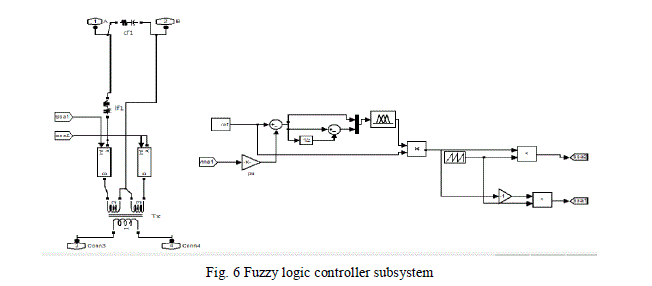 |
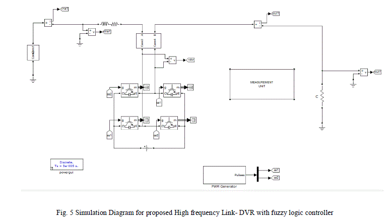
| The simulink model of HFL-DVR system with fuzzy logic controller is given in Fig.5. The DVR is connected in series with the distribution feeder. Input voltage condition for voltage sag and swell is created by changing the source voltage value. Fuzzy logic controller is used for control purpose as is given in Fig.6. The controller input is an error signal obtained from the reference voltage and the value of the injected voltage. The fuzzy input membership functions for error input and change in error input is shown in Fig.7-(a). The output membership functions for corresponding input membership functions based on fuzzy rules is given in Fig.7-(b). |
 |
 |
 |
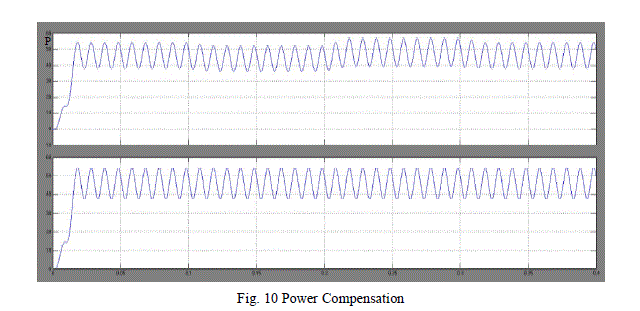 |
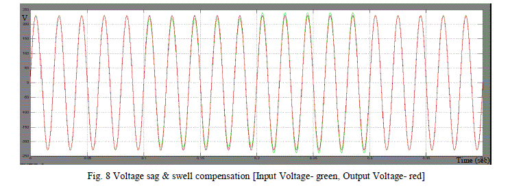
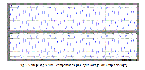
| The simulation results for single phase HFL-DVR system with fuzzy logic controller are given in Fig. 8-10. For the next 0.1 seconds, condition is of voltage sag and then from 0.2 seconds, the input voltage condition is of voltage swell. From the output voltage waveform given in fig.8 (b), it can be seen that both voltage sag and swell conditions are mitigated. The output voltage waveform, therefore, follows the reference voltage waveform [Fig.9]. The waveform for power during voltage compensation is given in Fig. 10. |
CONCLUSION |
| An improved topology for DVR system is proposed which is directly connected to the grid through the HFIT. The proposed HFL-DVR has relatively low cost, low loss, and small size and weight, as the number of semiconductor devices has been reduced. It is observed that Fuzzy logic controller can reduce the effect of input variations on the output voltage of DVR and compensate the voltage sag and swell conditions. Power compensation is also made possible. The simulation results using MATLAB/SIMULINK has been presented. The simulation shows that the proposed HFL-DVR performance is efficient and satisfactory in mitigating voltage sags/swells. |
References |
|