ISSN ONLINE(2278-8875) PRINT (2320-3765)
ISSN ONLINE(2278-8875) PRINT (2320-3765)
K.Venkateswarlu1 , Tegala. Srinivasa Rao2 and U Anjaiah3
|
| Related article at Pubmed, Scholar Google |
Visit for more related articles at International Journal of Advanced Research in Electrical, Electronics and Instrumentation Engineering
For the industrial applications which require the use of inverters, this is found to be a problem as an inverter consists of power semiconductor switches to control drives. To solve this problem, numerous multilevel inverter topologies have been introduced to enable the use of power semiconductor switches to convert higher power. This can be achieved by synthesizing a staircase output voltage waveform using a series of power semiconductor switches with several lower DC voltage sources such as capacitors, batteries, or renewable energy voltage sources. Here proposed hybrid multilevel inverter topology is derived from the multiple-transformer inverter topology. This front end complicates the implementation of converters that have a high number of levels. An alternative method of using lower voltage cells with floating dc links to compensate only for the voltage distortion of a neutral-point-clamped (NPC) converter is considered for active rectifier applications. The analogy between the floating HBs and the series active filters is used to develop a strategy for the harmonic compensation of the NPC output voltage and the control of the floating dc-link voltages and also reduces amount of THD in the output voltage of the multilevel inverter. The performance of the proposed hybrid multilevel inverter is verified through simulation of the proposed hybrid multilevel inverter topology and applied to PMSM drive to check the performance through MATLAB/SIMULINK Software Package.
Keywords |
| Multilevel Inverters, PMSM Drive, Current Control, Total Harmonic Distortion. |
INTRODUCTION |
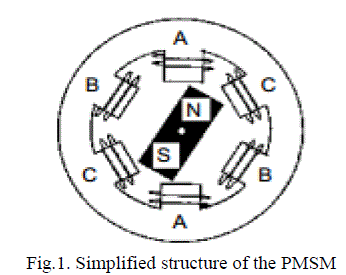
| A Brushless AC electric motor is an electric motor driven by an AC electrical input, which lacks any form of commutator or slip ring. Generally the term 'brushless AC motor' will refer to a permanent-magnet synchronous motor (PMSM) or permanent-magnet motor (PMM), a synchronous motor which uses permanent magnets rather than windings in the rotor. PMSMs are axial flux, radial flux, transverse flux, or flux switching depending on the arrangement of components, with each topology having different tradeoffs among efficiency, size, weight, and operating speed. Most PMSMs utilize permanent magnets which are mounted on the surface of the rotor. This makes the motor appear magnetically "round", and the motor torque is the result of the reactive force between the magnets on the rotor and the electromagnets of the stator. This results in the optimum torque angle being 90 degrees, which is obtained by regulating the d-axis current to zero in a typical FOC application [1]. |
| However, some PMSMs have magnets that are buried inside of the rotor structure. These motors are called Interior Permanent Magnet, or IPM motors. As a result, the radial flux is more concentrated at certain spatial angles than it is at others. This gives rise to an additional torque component called reluctance torque, which is caused by the change of motor inductance along the concentrated and non-concentrated flux paths. This causes the optimum FOC torque angle to be greater than 90 degrees, which requires regulating the d-axis current to be a fixed negative ratio of the q-axis current. The inverter is used to control the fundamental voltage magnitude and the frequency of the ac output voltage. AC loads may require constant or adjustable voltage at their input terminals, when such loads are fed by inverters, it is essential that the output voltage of the inverters is so controlled as to fulfil the requirement of the loads [2]-[5]. For example if the inverter supplies power to a magnetic circuit, such as a induction motor, the voltage to frequency ratio at the inverter output terminals must be kept constant. This avoids saturation in the magnetic circuit of the device fed by the inverter. |
 |
| The basic concept of a multilevel converter is to use a series of power semiconductor switches that properly connected to several lower dc voltage sources to synthesize a near sinusoidal staircase voltage waveform. The small output voltage step results in high quality output voltage, reduction of voltage stresses on power switching devices, lower switching losses and higher efficiency. Numerous multilevel converter topologies and wide variety of control methods have been developed in the recent literature [7]–[9]. Three different basic multilevel converter topologies are the neutral point clamped (NPC) or diode clamped [8], the flying capacitor (FC) or capacitor clamped and the cascaded Hbridge (CHB). The main drawbacks of NPC topology are their unequal voltage sharing among series connected capacitors that result in dc-link capacitor unbalancing and requiring a great number of clamping diodes for higher level. The FC multilevel converter uses flying capacitor as clamping devices. These topologies have several attractive properties in comparison with the NPC converter, including the advantage of the transformerless operation and redundant phase leg states that allow the switching stresses to be equally distributed between semiconductor switches [10] |
| In this topology, the NPC is used to supply the active power while the H-bridges (HBs) operate as series active filters, improving the voltage waveform quality by only handling the reactive power. In this way, this topology reduces the need for bulky and expensive LCL passive filters, making it an attractive alternative for large power applications [11], [13]. In this paper, the control strategy for the NPC-HBs hybrid converter, previously introduced in and this includes the low-frequency synchronous modulation of the NPC and the generation of the HBs voltage references for dc-link voltage control. |
PROPOSED HYBRID TOPOLOGY |
| For completeness and better understanding of the advances in multilevel technology, it is necessary to cover classic multilevel converter topologies. |
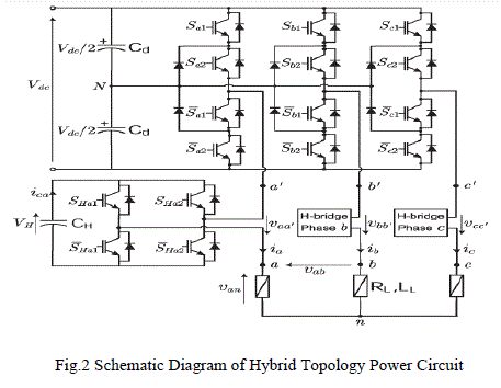 |
| A proposed hybrid multilevel inverter topology is derived from the multiple-transformer inverter topology by integrating the flying capacitor asymmetric H-Bridge inverter into the multiple transformer inverter topologies to improve the performance of a multilevel inverter. The considered hybrid topology is composed by a traditional threephase three-level NPC inverter, connected with a single phase HB inverter in series with each output phase [13]–[17]. The power circuit is illustrated in Fig. 2, with only the HB of phase a shown in detail. For testing as an inverter, the dc source for the NPC converter is provided by two series connected diode bridge rectifiers, arranged in a 12-pulse configuration. In the hybrid topology considered, the NPC inverter provides the total active power flow. For a highpower medium-voltage NPC, there are advantages to using latching devices, such as integrated gate-commutated thyristors (IGCTs), rather than insulated-gate bipolar transistors (IGBTs) due to their lower losses and higher voltage blocking capability, imposing a restriction on the switching frequency. In contrast, the HBs are rated at a lower voltage and need to be commutated at a higher frequency for an effective active filtering effect. This calls for the use of the IGBT. The proposed converter, shown in Fig. 1, can be analyzed from two different points of view. The first interpretation is as a single hybrid multilevel inverter with a nine-level phase voltage, achieved by the cascade connection of a three-level NPC leg and an HB per phase. The second interpretation is as an NPC converter with a series active filter that compensates for the harmonic content introduced by the low switching NPC stage. If the NPC bridge is to be modulated at a low switching frequency. |
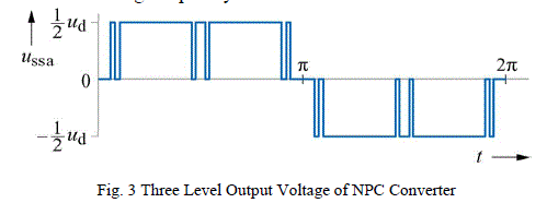 |
| For the modulation of the NPC inverter, the selective harmonic elimination (SHE) method has been selected. This method has the advantage of very low switching frequency and, hence, low switching losses while eliminating the low order harmonics. With the use of the SHE modulation, the fundamental output voltage of the converter is synthesized by the NPC converter, and thus, the series HBs will only need to supply reactive power, allowing for the operation with the floating capacitor dc links. A drawback of any synchronous modulation method, such as the SHE, is its limited dynamic capability and poor closed-loop performance due to the use of a pre-calculated lookup-table based approach, rather than real time calculations [18]. These drawbacks can, to a large extent, be overcome by the use of the series HBs which are modulated in real time, introducing an additional degree of control freedom to the circuit and cleaner feedback signals. The three-level SHE is an established and well-documented modulation strategy [19]. A qualitative phase output voltage waveform is presented in Fig. 3 considering a five-angle realization, so five degrees of freedom are available. This enables the amplitude of the fundamental component to be controlled and four harmonics to be eliminated. Since a three-phase system is considered, the triple harmonics are eliminated at the load by connection, and hence, they do not require elimination by the modulation pulse pattern. |
OPTIMAL CONTROL STRATEGY |
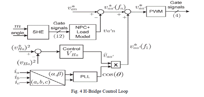 |
| Each series HB converter is independently controlled by two complementary references, as shown in Fig. 4. The first reference v*aa’(fn) corresponds to the inverse of the harmonics remaining from the SHE pulse pattern, calculated as described in the previous section from the difference between the NPC pulsed voltage pattern and its sinusoidal voltage reference. This calculation provides a fast and straightforward distortion estimation allowing for simple feed-forward compensation. Moreover, this voltage does not have a fundamental voltage component, and hence, it does not affect the floating average dc-link capacitor voltage. Nevertheless, to achieve a start-up capacitor charge and to compensate the voltage drift due to transient operation, an additional reference component for dc link voltage control is included. This second component of the voltage reference v*aa’(fn)) corresponds to a signal in phase with the load current. This voltage is used to inject small amounts of active power into the cell in order to control the HB dc-link voltage at its reference value v*H. During operation, the fundamental load current is generated by the NPC converter. In order to synchronize the voltage reference v*aa’(fn) with this current, a phase lock loop (PLL) algorithm is used, which guarantees a zero phase shift between both signals and therefore maximizes the active power transfer to the capacitors for any power factor. The magnitude of this voltage reference is obtained from the dc-link voltage controller shown in Fig. 4. For the design of this voltage controller, the dynamic model (2) of the dc-link voltage vHa as a function of v*aa is used. |
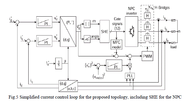 |
| For good dynamic performance, an outer load current loop can be implemented as shown in Fig. 5. As low order harmonics are compensated by the HBs, the current can be synchronously sampled with the HB carrier, providing a good estimation of its fundamental value. Moreover, as a high sampling frequency is used, a high current bandwidth can be achieved. It is important to note that, in applications with low frequency switching patterns, such as the SHE modulation, the use of direct synchronous sampling of the currents is not adequate to obtain the fundamental current because the switching harmonics do not cross zero at regular intervals. Instead, the observers are needed to extract the fundamental current values; otherwise, complex nonlinear control schemes are required [20]. In this paper, this problem is overcome by the compensating effect of the series-connected HBs, which moves the spectra from the non eliminated SHE harmonics to the high frequency HB carrier band. This effectively simplifies the outer load current control loop design, resulting in a standard dq frame linear current regulator as shown in Fig. 5. |
PERMANENT MAGNENT SYNCHRONOUS MACHINE |
| Inverter fed permanent magnet synchronous motor (PMSM) drives have widely been developed during the last decade. Several applications, such as rotor position sensorless drives and direct torque control drives, need fundamental armature voltage to calculate the armature flux linkage. Since the fundamental component of the actual voltage cannot be detected directly from the inverter output terminal, commanded voltage is usually used instead of the actual one. The development of high-quality permanent magnet materials into commercial production has encouraged several manufacturers to launch various permanent magnet synchronous machines (PMSM) into the market. Permanent magnet synchronous machines have been applied to servo drives for a long time already, and nowadays, there are quite large permanent magnet synchronous machines also in industrial use. In wind mill generators, the development has currently been in the direction of permanent magnet machines. In principle, vector control is required for controlling the PMSM [21]. Previously, the poor qualities of the magnetic materials could considerably restrict the implementation of a motor control. For instance, due to the poor demagnetization characteristics of AlNiCo magnets, the so-called id = 0 control was initially adopted in order to ensure the stability of the polarization. |
| The basic differences to the control principles of other AC motors are due to the magnetic properties of permanent magnets, and particularly to the fact that the permanent magnet material is a part of the magnetic circuit of the machine, and therefore has a significant influence on its reluctance. The relative permeability of permanent magnet materials μr is close to one, and therefore the effective direct air gap of the PMSM often becomes very large. Thereby also the inductances of the machine – particularly in machines in which the magnets are located on the rotor surface – usually remain rather low. Another difference is that the direct synchronous inductance, when employing embedded magnets, can be less than the quadrature value, while the ratio is the opposite in a separately excited salient-pole synchronous machine. |
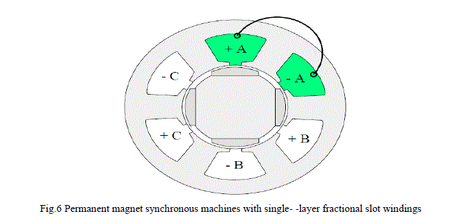 |
| Fig.6 shows the fractional slot wound PM synchronous machines. The characteristics of a permanent magnet machine are highly dependent on the rotor structure. The rotor can be implemented in various ways. When employing the modern permanent magnet materials, the rotor can be constructed even completely without iron. |
MATLAB MODELING AND SIMULATION RESULTS |
| The first phase of the work was to evaluate the proposed topology and control method.Here simulation is carried out in different cases, in that 1) Hybrid Multilevel Converter with Floating DC Link Controller. 2) Hybrid Multilevel Converter with Floating DC Link Controller Fed PMSM Drive. |
| Case 1: Hybrid Multilevel Converter with Floating DC Link Controller |
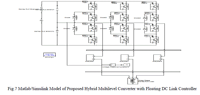 |
| Fig.7 shows the Matlab/Simulink Model of Proposed Hybrid Multilevel Converter with Floating DC Link Controller using Matlab/Simulink Platform. |
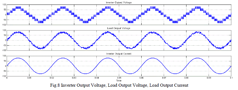 |
| Fig.8 shows the Inverter Output Voltage, Load Output Voltage, Load Output Current of Proposed Hybrid Multilevel Converter with Floating DC Link Controller. |
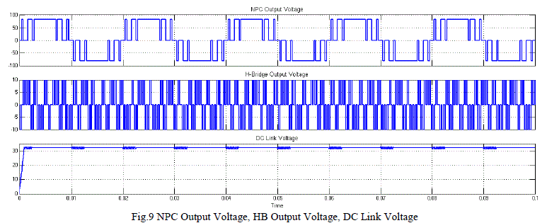 |
| Fig.9 shows the NPC Output Voltage, HB Output Voltage, DC Link Voltage of Proposed Hybrid Multilevel Converter with Floating DC Link Controller. |
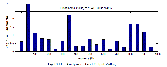 |
| Fig.10 FFT Analysis of Load Output Voltage of Proposed Hybrid Multilevel Converter with Floating DC Link Controller, get 9.42%. |
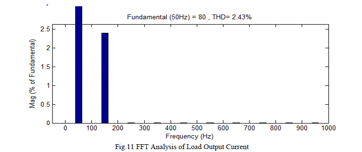 |
| Fig.11 FFT Analysis of Load Output Current of Proposed Hybrid Multilevel Converter with Floating DC Link Controller, get 2.43%. |
| Case 2: Hybrid Multilevel Converter with Floating DC Link Controller Fed PMSM Drive. |
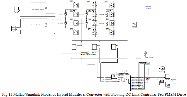 |
| Fig.12 shows the Matlab/Simulink Model of Hybrid Multilevel Converter with Floating DC Link Controller Fed PMSM Drive using Matlab/Simulink Package. |
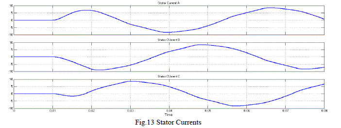 |
| Fig.13 Stator Currents of Hybrid Multilevel Converter with Floating DC Link Controller Fed PMSM Drive. |
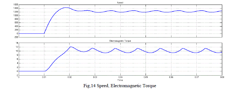 |
| Fig,14 Speed, Electromagnetic Torque of Hybrid Multilevel Converter with Floating DC Link Controller Fed PMSM Drive. |
 |
| Fig,15 Stator Back EMF of Hybrid Multilevel Converter with Floating DC Link Controller Fed PMSM Drive. |
CONCLUSION |
| The Permanent Magnet synchronous motors (PMSM’s) are widely used in high-performance drives such as industrial robots. It has characteristics of high efficiency, simple structure, high torque/inertia ratio, maintenance free and easy to control. The high torque density and high efficiency make PMSM as a better option as compared to induction motor drive. The Proposed Hybrid Multilevel Inverter topology is proven to improve the output waveform quality of the multilevel inverter by reducing the amount of THD in the output voltage of the multilevel inverter as well as the power efficiency of the multilevel inverter by reducing the amount of power losses in the power semiconductor switches through simulations software. The Proposed Hybrid Multilevel Inverter topology can be considered as a low cost solution for the need for a higher output waveform quality and higher power efficiency in an inverter which is suitable for stand-alone fuel cell operating systems as they are less sensitive to the size and weight of the system. The study on the Hybrid Multilevel Inverter topology with PMSM drive can be further expanded by simulating the multilevel inverter so as to provide a more detailed analysis on the static performance of the multilevel inverter fed drive, dynamic results are presented and THD well within IEEE standards. |
References |
|