ISSN ONLINE(2278-8875) PRINT (2320-3765)
ISSN ONLINE(2278-8875) PRINT (2320-3765)
ChandanSingh D. Rawat1 and Anuja D. Sarate2
|
| Related article at Pubmed, Scholar Google |
Visit for more related articles at International Journal of Advanced Research in Electrical, Electronics and Instrumentation Engineering
Pulse Compression Techniques are used in Radar systems to avail the benefits of large range detection capability of long duration pulse and high range resolution capability of short duration pulse with low power consumption. In this paper, details of these techniques are given which achieves high range resolution and low peak sidelobe levels under various noise conditions, Doppler shift and multiple target environments. The three very important Radar Pulse Compression techniques called Polyphase, Biphase and Linear frequency modulated (LFM) Codes are discussed in this paper considering their various parameters.
Keywords |
| Radar, Pulse Compression (PC), Peak Sidelobe Level (PSL), range resolution, sidelobes. |
INTRODUCTION |
| Radar is an acronym for Radio Detection And Ranging. It is an electromagnetic system used to detect and locate the object by transmitting the electromagnetic signals and receiving the echoes from the objects within its coverage [1]. Signal processing relies on the characteristic differences between signals from targets and the interfering signals [2]- [3]. Range resolution and maximum range detection are the two important factors for Radar waveform design. Range resolution is the ability of the Radar to separate closely spaced targets and it is related to the pulse width of the waveform. The narrower the pulse width the better is the range resolution. But, if the pulse width is decreased, the amount of energy in the pulse is decreased and hence maximum range detection gets reduced. To overcome this problem, Pulse Compression techniques are used in the Radar systems. Section 1 gives an introduction to Radar and Radar Pulse Compression. Section 2 discusses several journal papers on Radar Pulse Compression Techniques. The Need of Pulse Compression is explained in Section 3. Section 4 gives an idea about the Radar signals. The different Pulse Compression techniques are explained in Section 5. Section 6 discusses the comparison of all the techniques based on computer simulation results and the conclusion in Section 7. |
LITERATURE SURVEY |
| This section includes literature survey of few journal papers done on the contribution of Radar Pulse Compression Techniques in the advancement of Radars. |
| VijayRamya K. et al. [10] have proposed a new pulse compression technique for polyphase codes. In the proposed technique amplitude weighting is applied to a combination of the incoming signal and one-bit shifted version of the incoming signal. This technique produces better Peak Side lobe ratio (PSL) and integrated side lobe ratio (ISL) than all other conventional sidelobe reduction techniques. In simulation results the performance of Woo filter, Asymmetrical weighting and Amplitude weighting Techniques are compared with the proposed technique. Main lobe splitting which is the main disadvantage in Woo filter is eliminated in this techniques and implemented and incurs a minimal signal to noise ratio SNR loss. |
| In the Pulse-Compression Radar theory, the sidelobe reduction using synthesis of some proper nonlinear FM (NLFM) laws represents a major research direction. So to assure the sidelobe suppression, an adequate synthesis algorithm of NLFM signals based on stationary phase principle was proposed. Iulian-Constantin Vizitiu [11] have achieved experimental results which confirms significant sidelobe reduction without necessity to apply some weighting techniques. The analysis of the synthesized NLFM laws by ambiguity function tool is also discussed in [11]. |
| Pulse compression is usually a suitable substitute for the short pulse waveform except when a long minimum range might be a problem or when maximum immunity to repeater ECM (Electronic Countermeasures) is desired. Pulse compression radars, in addition to overcoming the peak-power limitations, have an EMC (Electromagnetic Compatibility) advantage in that they can be made more tolerant to mutual interference. This is achieved by allowing each pulse-compression radar that operates within a given band to have its own characteristic modulation and its own particular matched filter. H. A. Said et al. [12] implemented (LFM) linear frequency modulation digital pulse compression technique using (FPGA) which has distinct advantages compared to other application specific integrated circuits (ASIC). The FPGA provides flexibility, for example, full reconfiguration in milli-seconds and permits a complete single chip solution. |
NEED OF PULSE COMPRESSION |
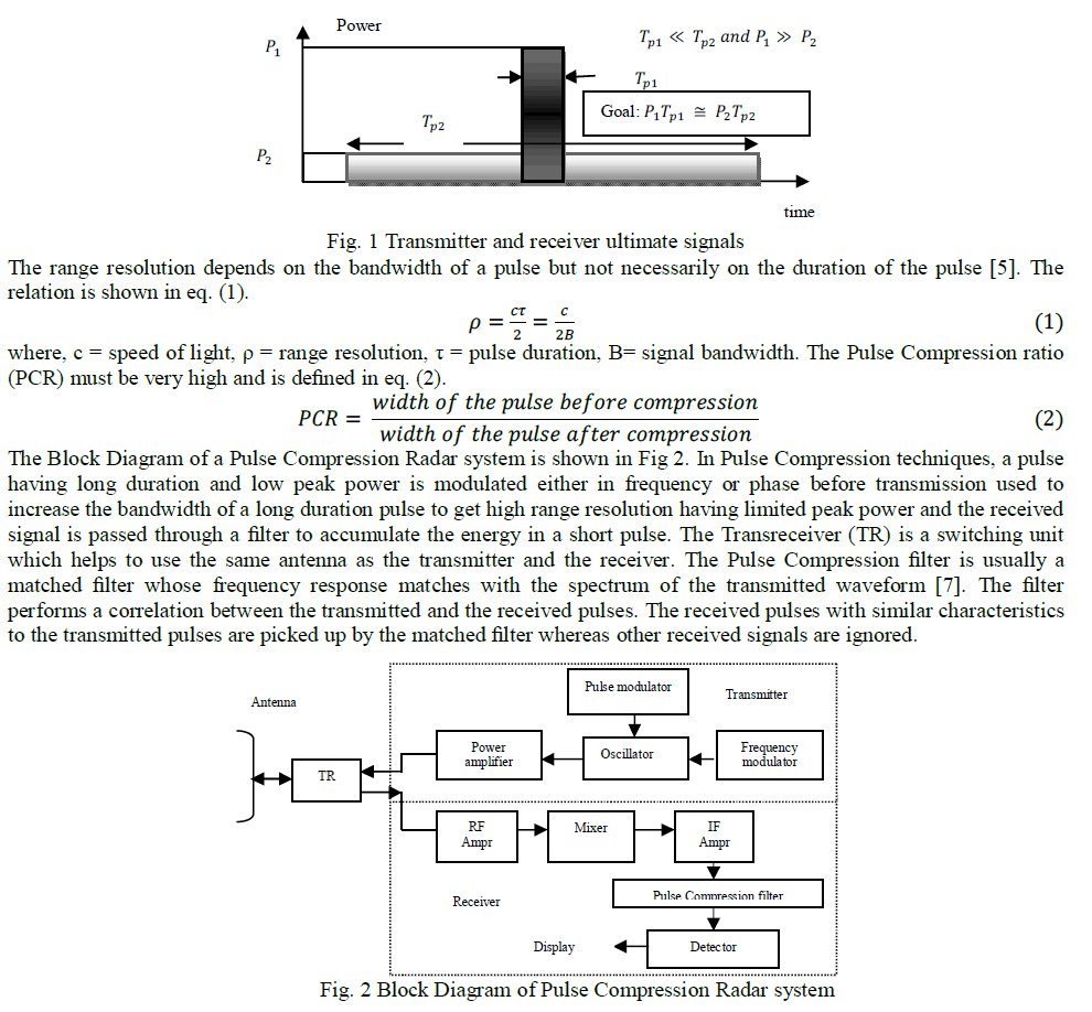
| Pulse Compression is an important signal processing technique [9] used in Radar Systems to reduce the peak power of a Radar pulse by increasing the length of the pulse, without sacrificing the range resolution associated with a shorter pulse [5]. Fig 1 illustrates two pulses having same energy with different pulse width and peak power. To get the advantages of larger range detection ability of long pulse and better range resolution ability of short pulse, Pulse Compression techniques are used in Radar systems [1]. |
 |
RADAR SIGNALS |
| In Radar systems a particular waveform is first determined for a given application and it is used to design the optimum detection system. The waveform should provide least amount of uncertainty or ambiguity when the reflected signal is used to extract the information about the range, the velocity and the number of true targets present in the environment. The different types of signals those are mostly used in Radar systems are discussed in [6]. These are Frequency modulated signal and Phase Coded signal. |
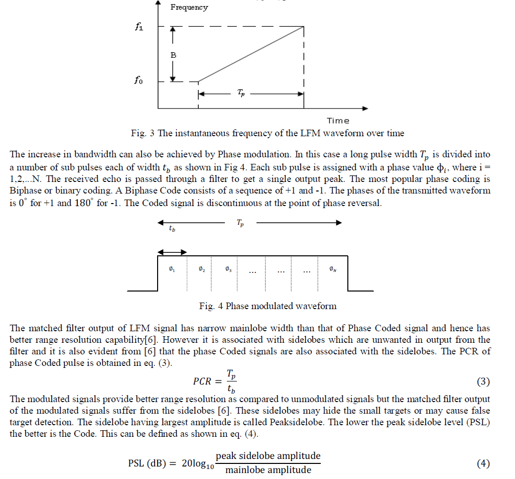
| Linear frequency modulated (LFM) signals are used in most of the Radar systems to achieve wide operating bandwidth. In this case, the frequency increases (up chirp) or decreases (down chirp) linearly across the pulse. The instantaneous frequency is a linear function of time, and hence is called as linear frequency modulation. Fig 3 illustrates the instantaneous frequency of LFM waveform that sweeps from f0 to f1. |
 |
PULSE COMPRESSION TECHNIQUES |
 |
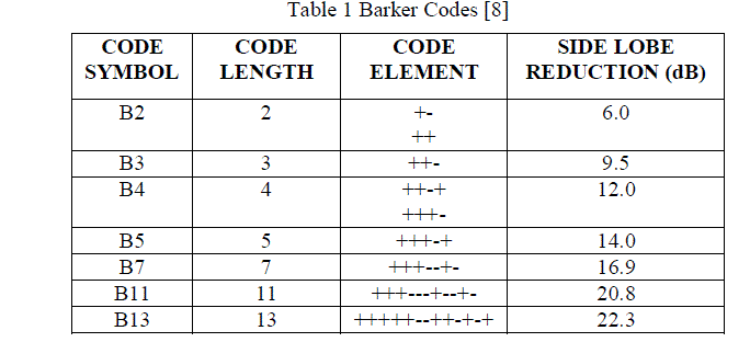 |
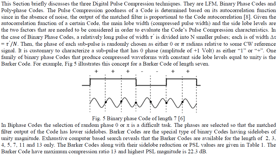
| If the pulse is allowed to take more than two values, it is known as a Polyphase Code. The phases of the Polyphase Code are chosen in such way that its ACF should have lower sidelobes. The binary phase Codes have better range resolution as compared to LFM [1]. Biphase Codes are easily generated and the correlators for these Codes are very simple. But the compressed output of Biphase Codes are associated with the high time range sidelobes and these Codes are more prone to Doppler shift. The application of a Pulse Compression technique depends on how efficiently it reduces the range sidelobes associated with the compressed waveforms. The number of Barker Codes available are very less and hence seriously suffer from security problem. Apart from Biphase Codes, Polyphase Codes and frequency modulated Codes are also used in Radar systems. PSL of Polyphase Codes are lower than that of the Biphase Codes. The frequency modulated and Polyphase Codes are more Doppler tolerant and have less range sidelobes compared to Biphase Codes. |
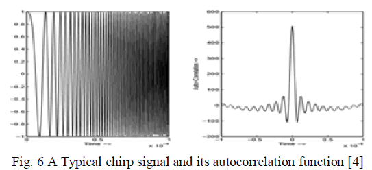 |
| In most of the practical Radar systems LFM waveform is extensively used because it is more Doppler tolerant than phase Coded signals. A compressed LFM signal at the receiver will produce a series of sidelobes surrounding the mainlobe and the first sidelobe occurs at a level of 13 dB below the peak of the mainlobe. Fig 6 represents a typical chirp signal and its autocorrelation function [4]. Range sidelobes are inherent part of the Pulse Compression mechanism and they occur due to abrupt rise in the signal spectrum. In place of LFM, Nonlinear LFM (NLFM) can be used for transmission which does not need any weighing at the receiver to overcome the mismatch loss but the NLFM signals are more affected by Doppler shift and are difficult to design than the LFM signals. |
| Phase Coded waveforms are more compatible for digital generation and compression [1]. However the Polyphase Codes are sensitive to Doppler shift. To overcome this problem the Polyphase Codes are derived from the phase history of the frequency modulated pulses [1]. The Codes such as Frank , P1 and P2 are derived from step approximation to LFM waveform. These Codes provide lower peak sidelobes than that offered by the best Biphase Codes [1] for a particular length. Two more Polyphase Codes, P3 and P4 are derived from the LFM signals. These Codes are more Doppler tolerant as compared to P1 and P2 Codes. When Doppler shift is zero these techniques substantially reduces the sidelobes of the compressed pulse. Grating lobes are appeared in the ACF of Frank and P1 Code with increase in Doppler shift. The P3, P4 Code has better sidelobe and Doppler shift characteristics. |
RESULTS AND DISCUSSION |
| The objective of a Pulse Compression technique is to achieve appreciable low PSL and acceptable range sidelobes in an economical manner. The types of waveforms used in the technique decide the cost and complexity of the Radar system. The efficiency of different approaches are evaluated by the PSL, hardware complexity involved and loss in SNR as compared to matched filter. Based upon these issues, Matlab simulation results are obtained for PSL of all the techniques, which illustrates that there are several comparisons in the Radar Pulse Compression Techniques. Simulations are carried out using Matlab v.2010 for all the Codes. |
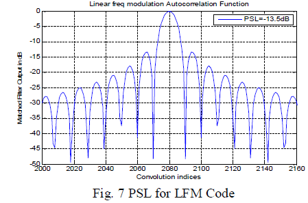
| Fig 7 illustrate PSL for LFM Code. It is seen that the PSL obtained here is 13.5dB down the main lobe which is very high. Such a high PSL can cause masking of weaker targets. Also the mainlobe is quite wide. The narrower the pulse width the better is the range resolution, so it shows that the range resolution of LFM Code is found to be very poor. |
 |
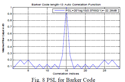
| Fig 8 illustrates PSL for Barker Code. It shows from this fig. that the PSL of Barker Code is -22.8dB which is lower than that of LFM Code. Also the mainlobe width of Barker Code is decreased and is quite narrow. This shows that the Barker Code has good range resolution compared to LFM Code. |
 |
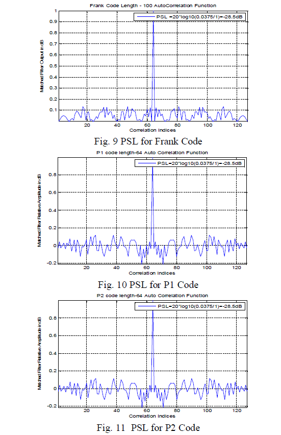
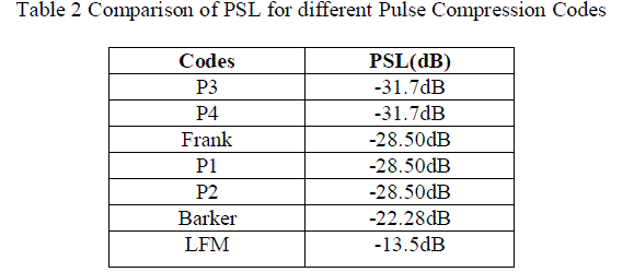
| Figs 9, 10 and 11 represents PSL for Frank, P1 and P2 Codes respectively which is -28.5dB. It is seen from all these figs that these Codes has very narrowband mainlobe width and very low PSL compared to LFM and Barker Codes. Hence Frank, P1 and P2 Codes have good range resolution and since PSL for Frank, P1 and P2 Codes is very low, so weaker targets are also prevented from masking. |
 |
| Figs 12 and 13 shows PSL for P3 and P4 Codes respectively which is the lowest of all the codes and is -31.7dB. These Codes also have very narrow mainlobewidth like Frank, P1 and P2 Codes but more advantage is that the PSL obtained of P3 and P4 is 3dB lower than that of Frank, P1 and P2 Codes. This is the benefit of P3 and P4 Codes that they have the lowest PSL of all the Codes. |
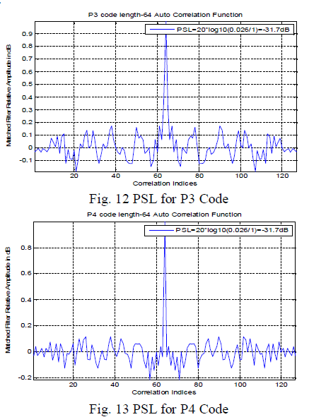 |
| Table 2 contains results obtained for PSL for Biphase, LFM and Polyphase Codes. The PSL for Polyphase Codes P3 and P4 is found to be the lowest of all the Pulse Compression Codes. |
 |
CONCLUSION |
| In this paper, the merits and demerits of different Pulse Compression techniques called LFM, Biphase and Polyphase Codes are known taking into consideration the important parameters like the mainlobe width, range resolution and PSL. All the results of the simulations illustrate that Polyphase Codes have lowest Peak Sidelobe Level (PSL) compared to Biphase Codes and LFM Codes, Biphase Codes and Polyphase Codes have better range resolution compared to LFM and the mainlobe width is wider for LFM but the number of range sidelobes are less compared to the other Codes. So Polyphase Codes are preferable in Radar Pulse Compression due to better range resolution and lowest PSL. |
References |
|