This paper deals with VSC based HVDC power transmission system. To increase the reliability of overall performance of the system. Use of Voltage source conversion makes system more comfortable to use for multi terminal and also for multi frequency system as per requirement of the load. Another technique is current source converter but these techniques have certain limitations as fixed frequency application and use of only two terminals for DC power transmission. This paper has also application of DFIG at the source end. By DFIG generation of active and reactive power can be control according to the requirement of load. Thus generating station has no need to change pressure of steam turbine as well as DC exciter setting. Thus controlling of DFIG and VSC is based on Direct and quadeture axis values of transmission line with PI controller
Keywords |
| VSC (voltage source converter), LCC (Line commutated converter), HVDC (High Voltage Direct
Current), HVDC (High Voltage Alternating Current). |
INTRODUCTION |
| The efficient power transmission via transmission lines is favorite topic among the researchers of the world. Three
phase AC transmission is classical method for transmitting the power form generating points to consumer ends but this
method have certain limitations as voltage regulation and other losses due to presence of inductance and capacitance of
the transmission line. As per researches of these days’ shows High Voltage Direct Current transmissions have more
advantage than classical three phase power transmission methods because of non effectiveness of inductance and
capacitance for HVDC power transmission system [2]. Thus HVDC power transmission technology is superior than 3
phase AC power transmission technology at the point of power transmission cost also means power transmission cost
increase more in three phase AC system to HVDC system for the same amount of increment in power transfer [6]. The
power transfer price will also raise more in AC than HVDC when distance of power transfer is increases. The power
carrying capabilities also show limitations when distance increase for power transfer in three phase AC system but
these limitations are not present in HVDC transmission system. Figure 1 shows variation of cost in DC power
transmission and AC power transmission. Thus for long distance power transmission DC power transmission is more
economy than AC power transmission. |
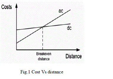 |
| The point where HVAC and HVDC curves cut each other is called breakeven point. The another advantage of
HVDC transmission is that it has capability to control the flow of by means of fast acting solid state devices like IGBT.
The problem of line compensation and asynchronous connection of grid has overcome with HVDC transmission. |
| The study shows that the multiterminal HVDC system and control strategy can reallocate the wind in the DC
network to achieve Constant power for long distant transmission to the load centre [1]. In history of energy
transmission, crucial moment was “War of Currents” in 19th century. From conflict between supporters of AC and DC
was winning Nikola Tesla. In effect, the most popular way to transmission energy is AC transmission lines. Despite
many advantages of AC transmission, in some conditions better is DC transmission, which demand presence of highvoltage.
The serious acceleration in development of this technology was 1954 when was built the first such system.
Since that time, HVDC has developed very intensive, and will be very important technology in problem of transmission
energy [11]. Power transmission among the wind forms and when there is more than one to be considered becomes
efficient by using VSC-HVDC system. The whole system is focused on to control power transmission by controlling
active and reactive power independently. |
| The 3 phase AC grid system need to be synchronized with each other from generation to transmission and
connected load but HVDC system have no need to be synchronized with each other due to use of rectifier and inverter
circuit. HVDC power transmission network provide freedom to connect load of different frequencies with same power
transmission network [5]. |
| There are basically two schemes to transmit the power in HVDC system i.e. |
| i) LCC-HVDC technique |
| ii) VSC-HVDC technique |
COMPARISON BETWEEN VSC-HVDC AND LCC-HVDC POWER TRASMISSION |
| Line commutated converter (LCC) HVDC can be also known as Current Sourced Converter which is basically a
Thyristor based technology and having self commutated Converter circuit with power switches (as Thyristor, IGBT,
GTO etc.) Line commutated converter also known as LCC technique. |
| This technique has dependency upon polarity appearance across the power switches of converter which causes self
commutation of connected power switches but Voltage source converter also known as VSC technique do not such
dependency upon appearance of polarity. Freedom against appearance polarity provide compatibility for connection of
more than one sending as well as more than one receiving end terminals. Thus VSC-HVDC system is more suitable for
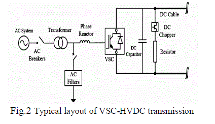
multi-terminal HVDC system. VSC-HVDC system needs auxiliary commutation circuitry to control the switching
action of power switches and thus power flow in the overall system, thus this system have better power flow controlling
capability with multi frequency load application due to each station have its own commutation priorities depending
upon the load requirements. Thus by above discussion we can observe that VSC based HVDC system have better
compatibility with multi terminal and multi frequency system application [3]. |
| The LCC-HVDC is line commutated means switching action takes place according to supply frequency i.e. either at
50Hz or at 60 Hz depending upon system designing, while VSC-HVDC systems have much higher switching
frequencies of 1-2 kHz. Therefore this rise in switching frequency the size of necessary filters is reduced and this
reduction of size effect cost as reduction [2]. |
| LCC-HVDC converters can control flow of reactive power only and this controlling of reactive power causes improvement in voltage profile of the system. VSC-HVDC systems can control the active and reactive power at both
ends and it can help to control the grid’s voltage and frequency of grid thus it enhance the overall power quality and
power factor of the system [8]. |
 |
| The generation proper switching signal for controlling the switching action perform by power switches is main concern
of sending end converter station for convert 3 phase current convert into Direct current and feed to HVDC buss bar
system. These direct value of line current and quadeture value of line current are compare with preset values of Id and
Iq in comparator circuit to generate error signal these error signals are fed to the controller here for PI controller is in
use due to having certain limit over transient response as peak overshoot and damping. Selection of PI controller is also
done on the basis of need to reduce the value of steady state error of the output of HVDC sending end station due to
HVDC transmission system have certain magnitude based limitation as pole length and insulation with each conducting
lines for DC power transmission capabilities[9]. |
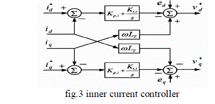
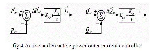
| For controlling switching of power switches connected depends either upon inner current controller or by outer current
controller. Both current controllers use to control DC link voltage, active and reactive power in VSC-HVDC system.
The inner current controller (ICC) transforms the converter current and the AC three phase voltages into the rotating
direct-quadrature (d-q) co-ordinate system. The outer controllers are used to generate and to provide reference currents
(iq & id) to ICC. |
 |
 |
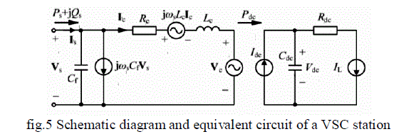
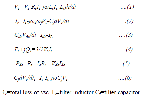
| The schematic diagram and the vector-based equivalent circuit of a VSC station in the synchronous dq reference
frame is shown in Fig.5 [1] |
 |
 |
SIMULATION RESULTS |
| Three phase power available at sending end station having following current waveform next fig. shows active as well
as reactive power flow at sending end station buss bar. |
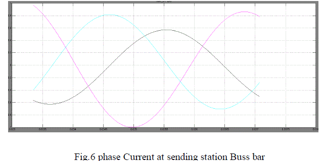 |
| The above figure 6 shows the waveform of three phase current transmitted from sending end to HVDC transmission
and fed to the sending end converter station by converting into DC. The output of the converter at the sending end
station is transmitting over long distance; this direct current is again fed to the receiving station as input and converted
into AC. |
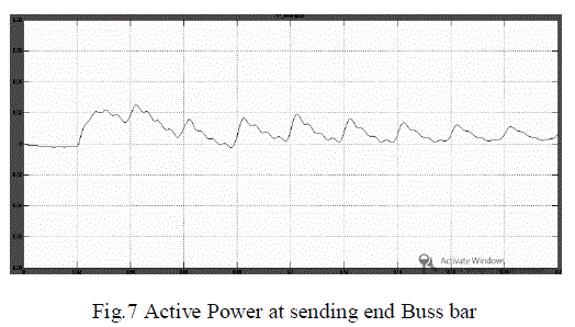 |
| Figure 7 shows the waveform of active power generated by generating station connected with sending ends of
HVDC power transmission system. This active power has dependency upon the load requirement across the receiving
end of HVDC power transmission. |
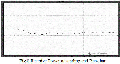 |
| Figure 8 shows the waveform of reactive power generated by generating station connected with sending ends of
HVDC power transmission system. This reactive power has dependency upon the voltage level across the sending and
receiving end of HVDC power transmission. |
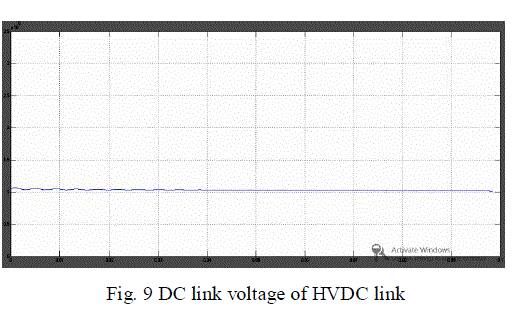 |
| The above figure 9 Shows the DC link voltage of HVDC power transmission line. This voltage level depends upon
the reactive power difference in between sending and receiving end stations and this difference will control active
power transmission between both sending end and receiving end station. |
CONCLUSION |
| The simulated results of active and reactive power of system shows the successful power transmission by VSC-HVDC
link which have integration with doubly fed induction generator wind turbine and conventional AC Grid at sending
end. VSC based power conversion technique is used to convert 3 phase AC current into DC current and fed to high
voltage DC link having link with sending end station while DC power is converted into AC power at receiving end by
similar VSC based conversion technique. Load connection at receiving end will cause to flow active and reactive power
flow at other end of the system. |
References |
- Yuan Fu1,a, Yi Wang1,b, YingliLuo,c, and XiangyuZhang,c, âÃâ¬ÃÅOperation and Coordinated Control of Multi-terminal VSC-HVDC Transmission System for Wind Power GenerationâÃâ¬ÃÂ,in International Conference on Power and Energy Systems Lecture Notes in Information Technology,
- N. Ahmed, A. Haider, D. Van Hertem, Z. Lidong, and H. P. Nee, "Prospects and challenges of future HVDC SuperGrids with modular multilevel converters," in Power Electronics and Applications (EPE 2011), 2011, pp. .
- D. Van Hertem and M. Ghandhari, "Multi-terminal VSC HVDC for the European supergrid: Obstacles," Renewable and Sustainable Energy Reviews, vol. 14, pp. 3156-3163, 2010.
- L. Xu, L.Yao, Bazargan, M., âÃâ¬ÃÅDC grid management of a multi-terminal HVDC transmission system for large offshore wind farms.âÃâ¬ÃÂProc. First SUPERGEN Conf., Nanjing, China, April 2009.
- Temesgen M. Haileselassie, Marta Molinas. Tore Undeland, âÃâ¬ÃÅMulti-Terminal VSC-HVDC System for Integration of Offshore Wind Farms and Green Electrification of Platforms in the North Sea,âÃâ¬Ã Proc. Nordic Workshop on Power and Industrial Electronics, June, 2008.
- L. Xu, L.Yao, Bazargan, M., Williams, B.W., âÃâ¬ÃÅControl and operation of multi-terminal dc systems for integrating large offshore wind farms.âÃâ¬Ã Proc. Seventh Int. Workshop on Large-Scale Integration of Wind Power and Transmission Networks for Offshore Wind Farms, Spain, May 2008.
- Chen Z.," Compensation schemes for a SCR converter in variable speed wind power systems", Power Delivery, vol. 19, pp. 813-821,2004.
- Bozhko S., Asher G., and Risheng L.," Large Offshore DFIG-Based Wind Farm With Line-Commutated HVDC Connection to the Main Grid: Engineering Studies", Energy Conversion, vol. 23, pp. 119-127,2008.
- H. Chong A.Q., Huang and M.E. Baran," STATCOM Impact Study on the Integration of a Large Wind Farm into a Weak Loop Power System", Energy Conversion, vol. 23, pp. 226-233,2008.
- Dawei X., Li R., and Bumby J.R.," coordinated control of an HVDC link and doubly fed induction generators in a large offshore wind farm", Power Delivery, vol. 21, pp. 463-471,2006.
- Tomasz Drobik,âÃâ¬Ã High-voltage direct current transmission linesâÃâ¬Ã IEEE Conference Publishing.2006
|