ISSN ONLINE(2319-8753)PRINT(2347-6710)
ISSN ONLINE(2319-8753)PRINT(2347-6710)
| Narendra Kumar Jena, Swati Samantray, Akshay Ku Das Department of electrical engineering, Siksha „O? Anusandhan University, Bhubanewar, Odisha, India |
| Related article at Pubmed, Scholar Google |
Visit for more related articles at International Journal of Innovative Research in Science, Engineering and Technology
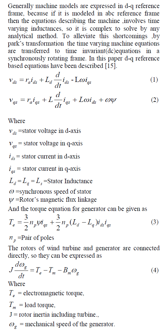
In the recent years Permanent magnet Synchronous Machines have proved themselves fairly suitable to be used as power generators in variable speed wind energy conversion systems. Due to their high power factor operation and maintenance free operation these machines are gaining attention of researchers and manufacturers. In this paper A PMSG based wind energy system has been proposed, where the PMSG is connected to the grid through two back to back bidirectional converters .This work only emphasizes on the control of the machine side converter and the dc link voltage is assumed to be constant. The machine-side converter (MSC) is controlled by a vector control strategy which employs a conventional PI controller and three hysteresis band controllers for the control of torque and speed. Due to the vector control strategy decoupled control of torque and flux has been achieved in this paper. The whole modeling and simulation has been performed in MATLAB/SIMULINK and the results has been analyzed in the paper.
Keywords |
| Permanent magnet synchronous generator(PMSG), Vector control scheme, Hysteresis band controller. |
INTRODUCTION |
| Wind energy is regarded as a significant renewable energy source in recent years. These are getting a lot of attention, because they are cost competitive, environmentally clean and safe renewable energy sources, if we compare them to fossil fuel and nuclear power generation. Variable-speed wind energy systems have many advantages over fixedspeed generation such as increased energy capture, Operation at maximum power point, improved efficiency, and power quality [14,16,17].There are several configurations available in variable speed wind generation systems [14], the most common in high power turbines being the doubly fed induction generator (DFIG)[18]. In this topology, the stator is directly connected to the grid and the speed is controlled through the rotor by a bidirectional back to back converter. However permanent magnet synchronous generators (PMSG) have received much attraction in wind-energy application. Due to the fact of easy realization of multiple pole design in synchronous generators, it provides a realistic gearless operation. The absence of a gearbox and the lack of moving contacts on the PMSG increase the reliability and decreases the maintenance requirements also enable the wind energy system to be light-weight [1-6]. Moreover it has a property of self-excitation, which allows an operation at a high power factor and high efficiency [1-6]. The use of permanent magnet in the rotor of the PMSG makes it unnecessary to supply magnetizing current through the stator for constant air-gap flux; the stator current need only to be torque producing. Hence, for the same output, the PMSG will operate at a higher power factor because of the absence of the magnetizing current and will be more efficient than other machines [7-13]. A sensor-less scheme is proposed in the whole wind energy system to further improve the characteristics. Problems related with electromagnetic interferences in the position signals and failures in the position sensor are avoided by implementing the scheme [2]. Additionally, wind generation system are not operated at a very low speeds, therefore the difficulties associated with low back-emf for flux estimation in sensor less strategy are not severed in this application. The sensor less scheme proposed here is based on a synchronous d-q frame phase-locked loop (PLL) as those used in phase detection for grid connected converters [2]. |
| In this paper the modelling and dynamic behavior of direct driven variable speed medium power based PMSG has been emphasized.This paper has been embodied with the concept of vector control with hysteresis band controller to control the decoupled active and reactive power. The whole system is simulated in Matlab / Simulink environment and results have been analysed.his document is a template. |
SYS TEM OVERVIEW |
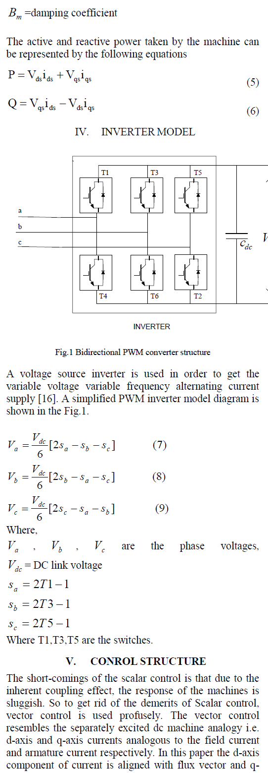
| The wind energy conversion system shown in Fig.3 comprises of wind turbine, PMSG, Hysteresis Band Current Controller and PWM bidirectional converter. |
| The output of PMSG is not suitable for use because it generates power at variable voltage and frequency due to variable wind speed. So it is converted to constant DC voltage at the DC link to be directly used as a dc source or for storage or further inverted into AC and synchronized to a grid. A vector controlled IGBT based inverter is used to regulate the speed, active power and reactive power of the PMSG during the wind speed variation. |
M ODELING OF PMSG |
 |
 |
| axis component current is 90 degree ahead of it. The daxis current controls the reactive power and q-axis current controls the active power. So the active and reactive power are decoupled and can be controlled easily and independently [16]. |
| In the vector control block diagram as shown in the fig() the reference current qs i has been derived from a speed control loop. In this speed control loop a PI controller has been used having the control structure as shown in the fig().the mathematical model for PI is |
 (10) (10) |
| Where „u(t)‟ is the controller output, e is the error, „Kp‟ and „Ki‟ are the proportional and integral gains of the PI controller. |
| Here the rotor angle θ and rotor speed ω has been tracked from the generator and converted to its electrical equivalent. The error signal of the measured speed and reference speed is processed through a PI controller to get * qs i .The d-axis generator current reference is set as, * ds i =0,because the rotor flux is supplied by the Permanent Magnet. |
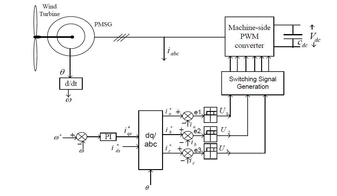
| The current tracked from the generator and the conversed reference currents are compared and pass through a Hysteresis Band controller. The Hysteresis Band controller has been described the following equations: |
 |
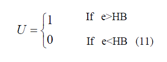 |
| Where e=error signal |
| U = output of the hysteresis band controller |
| HB = hysteresis band width. |
| In this work the hysteresis band width is set to 0.1 and it remains constant throughout the control process. Adaptive hysteresis band width schemes are also available but this paper doesn‟t emphasize on this schemes. The hysteresis band working is described by the Fig.2. |
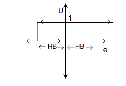 |
| Fig.3 Hysteresis band controller |
| The signals generated by the hysteresis band controller have been given to the Inverter through Switching Signal Generator. |
SIMULATION AND RESULTS |
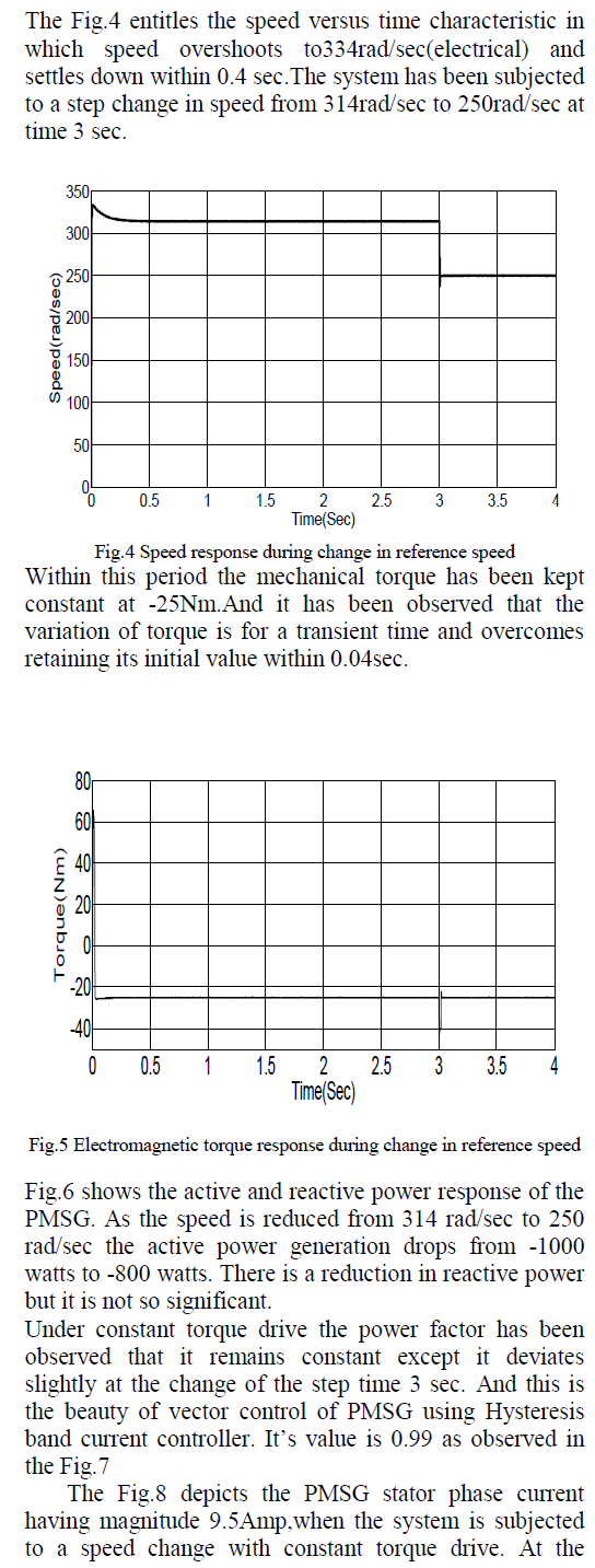
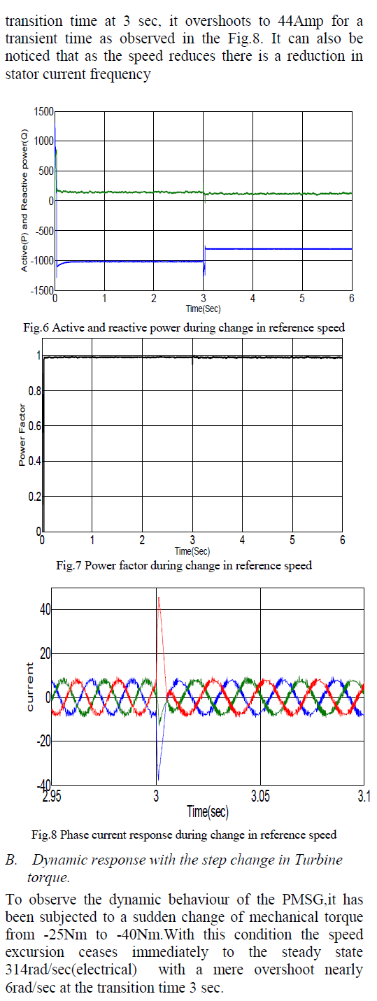
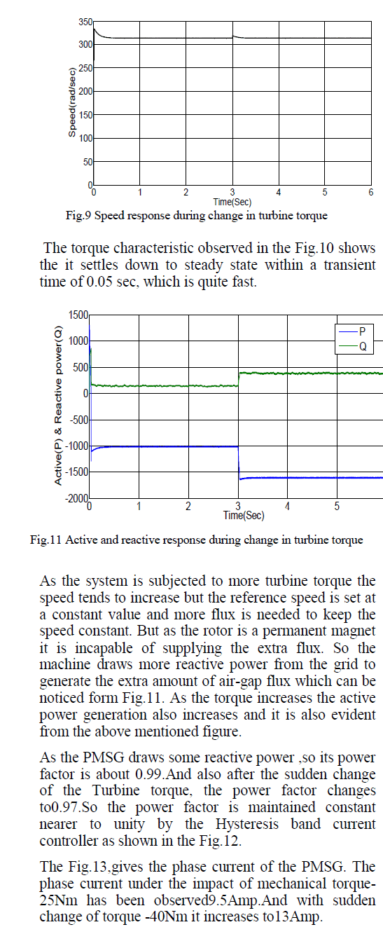
| A. Dynamic response with the step change in reference speed. |
 |
 |
 |
 |
CONCLUSION |
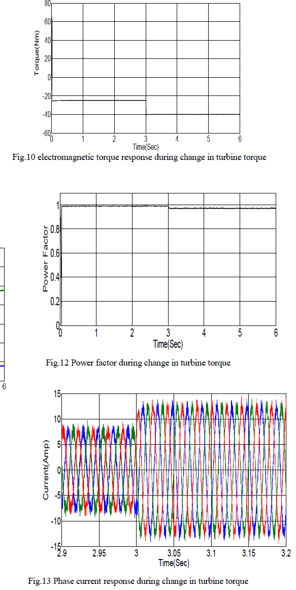
| The wind energy system employing PMSG as the wind power generator has been successfully modeled and simulated in the proposed work. The result analysis clearly shows that the vector control strategy for the control of the machine side converter works well, which in turn enables decoupled control of torque and speed. The power factor at which the PMSG generates power is above 0.95 which is quite good, in wind energy system point of view. The system gives quite fast response which proves the proposed model is efficient for variable speed wind power extraction. |
| APPENDIX |
| Table-I |
 |
| Table-II |
 |
References |
|