ISSN ONLINE(2320-9801) PRINT (2320-9798)
ISSN ONLINE(2320-9801) PRINT (2320-9798)
DR. A. MUTHU KUMARAVEL1
|
| Related article at Pubmed, Scholar Google |
Visit for more related articles at International Journal of Innovative Research in Computer and Communication Engineering
It is almost safe to state that there are no applications where images are acquired or processed which do not have active or potential work on image restoration. In the center of work lies an FPGA implementation of an iterative image restoration algorithm. Hardware design for the image restoration algorithm and estimations on the performance of the FPGA implementation is presented. During the restoration of an image each region is restored for as much iteration until the convergence criterion is met. The hardware solution primarily exploits the concept of parallelism in order to gain speed-up against software implementations. Since excessive amount of hardware is needed to restore image of practical size, statistical method for analysis of images is done and hence images are segmented. Results show that the speedup gained for practical systems varies between 6.5 and 10.2 for different images.
INTRODUCTION |
| Images are produced to record or display useful information. Due to imperfections in the imaging and capturing process, however, the recorded image invariably represents a degraded version of the original scene. Restoration is the process of recovering information eliminated by the degradation process, by operating on the available degraded image and obtaining a restored image as close as possible to the original one. The field of image restoration which sometimes referred to as image deblurring or image deconvolution is concerned with the reconstruction or estimation of the uncorrupted image from a blurred and noisy one. Essentially, it tries to perform an operation on the image that is the inverse of the imperfections in the image formation system. |
| The purpose of image restoration is to "compensate for" or "undo" defects which degrade an image. Degradation comes in many forms such as motion blur, noise, and camera misfocus. In cases like motion blur, it is possible to come up with a very good estimate of the actual blurring function and "undo" the blur to restore the original image. In cases where the image is corrupted by noise, the best way is to compensate for the degradation it caused |
| Several methods are used in the image processing world to restore images. A large number of techniques have appeared in the literature to provide solutions to the restoration problem. A hardware implementation of an iterative image restoration algorithm on the FPGA (Field Programmable Gate Array) platform is presented. The work is based on a basic iterative restoration algorithm. A very important aspect of the hardware implementation is its running time. The possible speedups that can be achieved by implementing this algorithm on reconfigurable hardware as compared to the implementation of the algorithm using software is investigated. |
II. ITERATIVE IMAGE RESTORATION ALGORITHM |
| The idea behind the iterative procedure is to make some initial guess of f based on g and to update that guess after every iteration. The procedure is |
| 0(n1,n2) =λg(n1,n2) |
| k+1 (n1,n2) = k(n1,n2) + λg(n1,n2) - k(n1,n2)**b(n1,n2) |
| where 0 is an initial guess based on g. If k is a good guess, eventually convolved with b will be close to g. When that happens the second term in the k+1 equation will disappear and k and k+1 will converge. λ is convergence factor and it lets us determine how fast k and k+1 converge. |
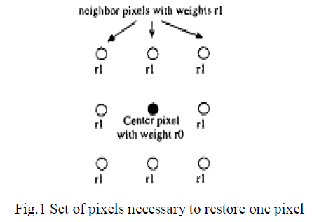
| Convolution is one of the most common operations on an image that is performed in the spatial domain in which a kernel of numbers is multiplied by each pixel and its neighbors in a small region, the results summed, and the result used to calculate the new value of the pixel. This method is also used in edge detection, for sharpening points and lines, and smoothing of images. For the restoration of a pixel, the immediate eight neighbors around the pixel are used. We define these pixels as 1-neighbors, designating that they are at distance 1 to the center pixel. Accordingly the i-neighbors are defined to be those pixels, that are at distance i to the center pixel. |
 |
| Among different image restoration algorithms iterative algorithm is focused due to several reasons. The algorithm possesses a pattern of local computations due to the dependency of a pixel’s restored value on its 1- neighbors. Those types of computations allow a spatial implementation. |
| Also, the same local computation is repeated for a number of iterations and on a considerable amount of data. Some difficulties or challenges related to the algorithm exist as well. The task is bound to be sequential in the sense that all pixels of the image have to pass through the current restoration step until the next iteration step can start. This demands a fast and large bandwidth communication line that simply is not available. Thus, segmenting the image and processing each segment independently becomes a necessity. |
| In turn, edge effects became more important and the algorithm needed to have another modification to deal with this issue. As a result, this algorithm needed to go through some fundamental modifications in order to comply with the resource and communication limitations. The criteria for convergence is the residual, which is calculated as |
 |
| The iteration stops when residual <λ, where λ is a threshold set at the beginning. The value of determines the number of iterations for convergence, hence the convergence time. |
| A.Software versus Resource Bounded Hardware |
| The outline of image restoration algorithms is as follows: |
| 1. Initialize residual |
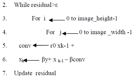 |
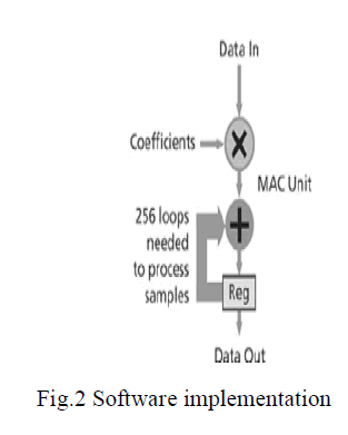
| As it can be seen from the pseudo code, the algorithm operates on one pixel at a time, scanning through the image and the iterations are repeated as many times as the stopping criterion dictates. This sequential implementation is very slow. |
 |
B. Hardware Implementation |
| Our motivation behind the hardware implementation was to come up with a faster solution.The basic setup of the hardware implementation consists of some medium to store the image data and a processor to perform the restoration. The memory that contains the data is communicating with the processor through a channel. |
| The algorithm could have been implemented in hardware just as in the software model, sending 9 pixel values to the processor at a time, letting the processor compute the new value for the center pixel and writing the new value back. That would have to be repeated for several iteration steps. Since the communication between the memory and the processor is slow that would introduce a large delay. An improved way to perform this task is to utilize the parallelism of the algorithm [5, 61. Since at each step the same restoration operation is performed on each pixel, a piece of hardware is configured on the FPGA to perform this task, which is called a processor in this context. |
| By assigning a pixel to each processor all pixels can be processed in parallel which increases the performance in terms of speed substantially. Also, loading the pixel values onto the FPGA once, performing several iterations and then writing the result back to the memory, decreases the overhead of communication between the FPGA board and the memory unit. This model is not realistic because of the limited hardware resources. |
| The number of processors that can fit into an FPGA chip is a lot less than the number of pixels contained in the images we usually deal with. Therefore we need to segment images. Images are segmented into regions of size mx n such that there are enough number of processors on the FPGA chip to process all of them in parallel as desired and each time one segment is loaded onto the FPGA. After the restoration of one segment is completed the data is written back and the next segment is loaded. |
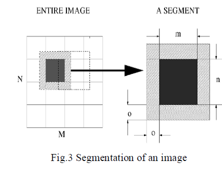 |
| One solution to lessen this effect is to allow the segments to overlap. Segments of sizes (m+o) x (n+o) are restored and then the overlapping portions are discarded. Figure 2 shows the segmentation of an image and the dimensions of one segment. If the algorithm runs k iterations, the first k pixels starting with the pixel at the boundaries will be affected by the boundary effect. Hence ideally segments should overlap by as many pixels as the number of iteration steps. This would not be very practical because for large number of iterations the overlapping regions would again overflow the FPGA with pixels. |
| Under this condition smaller overlapping regions are chosen in expense of some error introduced into the pixel values. The pixel values at the boundaries get corrupted due to the boundary effect in the first iteration, in the next iteration the pixels at a distance of 1 get affected, in the third iteration the neighbor pixels at distance 2 will have an error term in their pixel values and so on. The neighbor pixels have a weight rl as shown in Figure 1, which is a number less than one. Also the weighted sum of the center pixel and the neighbor pixels is multiplied by the gain parameter PI which is also smaller than one. The degradation introduced at the boundaries will diffuse into the interior of the image while being multiplied by these coefficients raised to a high power, hence the error will become negligible after a point. |
III. HARDWARE ASPECTS OF THE DESIGN |
| In this section, the hardware implementation of the iterative image restoration algorithm is discussed. The structure of the processing unit and the whole system consisting of the FPGA board and the host processor is examined closely. |
A. Resource Planning and Scheduling |
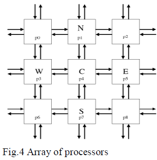
| Using this hardware platform, one (m+o) x (n+o) segment is processed at a time. After the computation, an m,n segment is sent back. The basic building block of the hardware is the processor, which is loaded with one pixel value and takes the eight neighboring pixel values as input. That block computes the next iteration value of one pixel.Each processor can exchange data with the surrounding eight neighbors, i.e., data can move in both directions between processors. Fig.4 shows such an array of processors. |
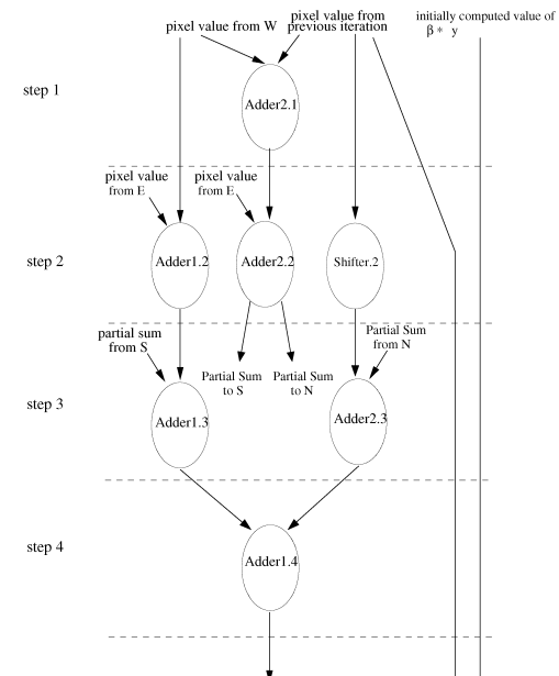
| Each processor contains two adders, one shifter, and one subtractor. The multiplication and division operations, which are used for the weighted sum computations, are performed by the shifter for this application. In practice, the fastest implementation would be to multiply the center pixel by an integer representing its weight and its eight immediate neighbors by another integer representing the weights of the neighbors, sum the products, then divide the total by the common denominator. |
 |
| For example, if the center pixel is assigned the weight ½ and the neighbors have weight of 1/16 ,then first, the center pixel is multiplied by 8 a weight of 16 and the neighbors are multiplied by1,which doesn’t require an actual multiplication, and then the sum of the products is divided by 16.Choosing the weights to be powers of 2 allows the computation to be extremely fast by performing only bit shifting. Taking this into consideration, the weights used for the center pixel and the neighboring pixels, as well as the gain parameter, are chosen to be powers of 2. |
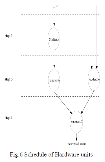
| As a result, multiplication and division operations are performed by shifters as left and right shifts, respectively. The hardware units of the processor are scheduled in order to be utilized in the most efficient way. Fig.3 presents the utilization of the hardware units in corresponding clock cycles. The computations performed by each functional unit at each step is illustrated. In order to fully utilize the parallelism of the algorithm, it is desirable to fit as many processors into the FPGA chip as possible. |
| B Different series of FPGA |
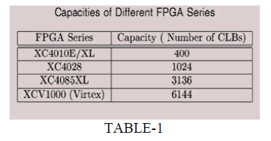
| On the other hand, the implementation is resource constrained. Hence, there is a limit on the number of processors that the design can contain, which is dictated by the amount of hardware resources available. As a result, the size of the array of processors depends on the capacity of the FPGA chip that is being used for the implementation |
 |
 |
| The hardware design is described using VHDL and the design is synthesized using Xilinx Foundation Series F1.5 Software. For the timing analysis the hardware is assumed to contain an 8 x 8 array of processors with 2 pixels overlap allowed for each segment. Figure 4 presents the estimated speed-up over software implementation. The reconfigurable processor that restores the image is communicating with a host processor. The image is stored on the host processor and the final result is also written back to the host processor. |
| The running time on hardware has been estimated by calculating the number of clock cycles required for the restoration and then adding the transfer time. The required number of clock cycles are derived from the scheduling. The data transfer time has been estimated by considering real applications. |
| The shifter has been selected, because it requires significantly less area than a multiplier and allows faster computation for our application. The subtraction can also be performed by using one of the existing adders and some extra hardware to invert one of the numbers to be added In Table1 capacities of different Xilinx FPGAs have been shown. |
 |
IV. STATISTICAL ANALYSIS OF IMAGES |
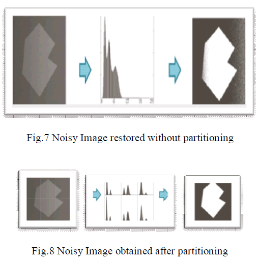
| Due to resource constraints the whole image cannot be processed in parallel. a method to segment images considering the convergence properties of the algorithm is presented. During the restoration of an image each region is restored for as many iterations until the convergence criterion is met. Convergence depends on several factors, such as the gain parameter 0, the choice of the weights of the center pixel and the neighboring pixel, and the distribution of pixel values over the entire image. In this work the correlation between the pixel value distribution of an image and the convergence time of its restoration is investigated. If such a correlation is determined, methods can be devised to detect it and exploit it in order to improve convergence time. |
| The first task was to investigate whether there exists a correlation between the pixel values in a region and the number of iterations required for that region. A statistical method to determine this and the standard deviation of pixel values in a region has been chosen as a metric. The standard deviation gives indication on how much the pixels values in a region are spread apart. For each region of the partitioned image the standard deviation of the pixels inside the region has been calculated and also the number of iterations required for the region is determined. |
| Following this observation the question is whether it is possible to use different methods to partition images so that the resulting distribution of pixels in the regions would require less number of iteration steps. The first approach would be to have a fixed partitioning window, and try different orientations of this window on the image. This window can be displaced by a certain number of pixels, and the next partition would start where the first ended. |
 |
V. CONCLUSION |
| In this paper a reconfigurable solution to the hardware implementation of image restoration is presented. Issues discussed are related to many phases of the design process, starting from the algorithmic modifications, throughout the hardware design and further techniques to improve execution time. A hardware solution which primarily exploits the parallelism of the application in order to gain speed-up against software implementations is given. Concerning the techniques to improve execution time, the correlation between the convergence time of an iterative image restoration algorithm with the distribution of pixel values is studied. Statistical analysis on several images revealed that a correlation exists between the standard deviation of pixel values in a region that is being restored and the number of iterations required. |
References |
|