ISSN ONLINE(2320-9801) PRINT (2320-9798)
ISSN ONLINE(2320-9801) PRINT (2320-9798)
Shivani Jain, Jyoti Rani
|
| Related article at Pubmed, Scholar Google |
Visit for more related articles at International Journal of Innovative Research in Computer and Communication Engineering
Image enhancement is based on the multi scale singularity detection with an adaptive threshold whose value is calculated via maximum entropy measure. Wavelet transforms are used because of their inherent property that they are redundant and shift invariant. Intensity changes occur at different scales in an image, so that their optimal detection requires the use of operators of different sizes. So, a vision filter should be a differential operator, and it should be capable of being tuned to act at any desired scale and the wavelets are ideal for this. Principle objective of Image enhancement is to process an image so that result is more suitable than original image for specific application. This paper will provide an overview of underlying concepts commonly used for image enhancement.
Keywords |
| Image enhancement, spatial domain, Frequency domain, DCT, DWT, Wavelet Transform. |
INTRODUCTION |
| Image enhancement is a process principally focuses on processing an image in such a way that the processed image is more suitable than the original one for the specific application. The word “specific” has significance. It gives a clue that the results of such an operation are highly application dependent. In other words, an image enhancement technique that works well for X-ray topographic images may not work well for MR images [1]. The principal objective of image enhancement is to modify attributes of an image to make it more suitable for a given task and a specific observer. During this process, one or more attributes of the image are modified. |
| We use wavelet transforms because of their inherent property that they are redundant and shift invariant These transforms are used to decompose the given low resolution image into frequency components i.e., sub bands. The enhancement methods can broadly be divided in to the following two categories [1] [2]: |
| 1. Spatial Domain Methods |
| 2. Frequency Domain Methods |
| In spatial domain techniques [3], we directly deal with the image pixels. The pixel values are manipulated to achieve desired enhancement. In frequency domain methods, the image is first transferred in to frequency domain. It means that, the Fourier Transform of the image is computed first. All the enhancement operations are performed on the Fourier transform of the image and then the Inverse Fourier transform is performed to get the resultant image. These enhancement operations are performed in order to modify the image brightness, contrast or the distribution of the grey levels. As a consequence the pixel value (intensities) of the output image will be modified according to the transformation function applied on the input values. |
| Image enhancement simply means, transforming an image f into image g using T. (Where T is the transformation. The values of pixels in images f and g are denoted by r and s, respectively. As said, the pixel values r and s are related by the expression, |
| s = T(r) eq. (1) |
| Where T is a transformation that maps a pixel value r into a pixel value s. The results of this transformation are mapped into the grey scale range as we are dealing here only with grey scale digital images. So, the results are mapped back into the range [0, L-1], where L=2k, k being the number of bits in the image being considered. So, for instance, for an 8-bit image the range of pixel values will be [0, 255]. |
II. WAVELET TRANSFORM |
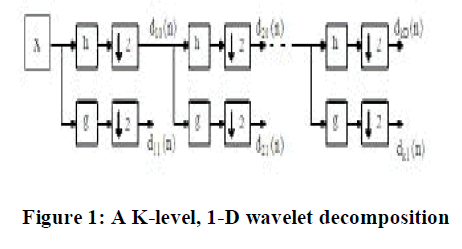
| The generic form for a one-dimensional (1-D) wavelet transform is shown in Fig. 1. Here a signal is passed through a lowpass and high-pass filter, h and g, respectively, then down sampled by a factor of two, constituting one level of transform. Multiple levels or “scales” of the wavelet transform are made by repeating the filtering and decimation process on the lowpass branch outputs only. The process is typically carried out for a finite number of levels K and the resulting coefficients [1], |
| d i1(n),i€{1,….,K} and dK0(n) eq.(2) |
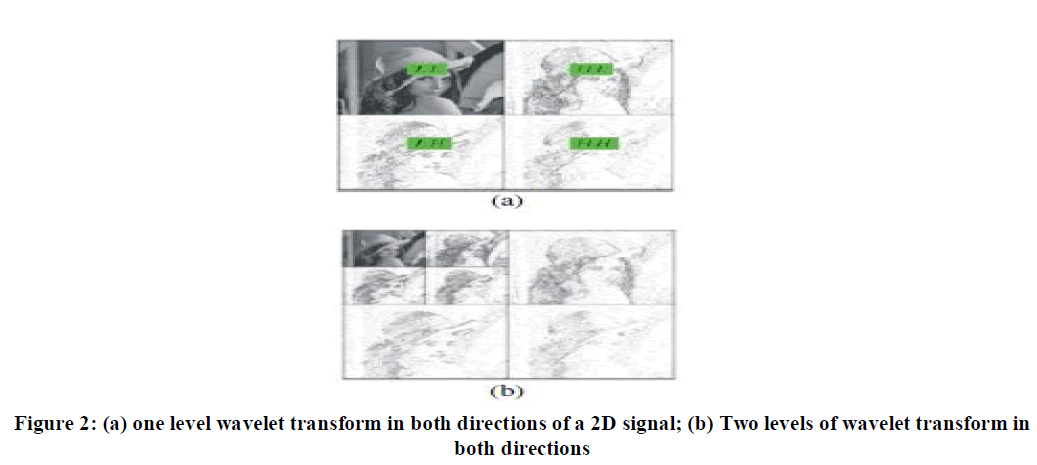
| are called wavelet coefficients. Referring to Fig. 1, half of the output is obtained by filtering the input with filter H(z) and down sampling by a factor of two, while the other half of the output is obtained by filtering the input with filter G(z) and down-sampling by a factor of two again. H(z) is a low pass filter, while filter G(z) is a high pass filter. The 1-D wavelet transform can be extended to a two-dimensional (2-D) wavelet transform us in separable wavelet filters. With separable filters the 2- D transform can be computed by applying a 1-D transform to all the rows of the input and then repeating on all of the columns. Using the Lena image in Fig. 2a shows an example of a one-level (K = 1), 2-D wavelet transform. The example is repeated for a two-level (K = 2) wavelet expansion in Fig. 2b. |
 |
 |
| From Fig. 2a sub band LL is more important than the other 3 sub bands, as it represents a coarse version of the original image. The multi-resolution features of the wavelet transform have contributed to its popularity. |
III. DWT (DIRECTIONAL WAVELET TRANSFORM) |
| Natural images are not simple stacks of 1-D piecewise smooth scan–lines; discontinuity points (i.e. edges) are typically located along smooth curves (i.e. contours) owing to smooth boundaries of physical objects. Thus, natural images contain intrinsic geometrical structures that are key features in visual information [3]. In order to identify such structures, their orientation bears a crucial piece of information. The wavelet transform [4] has a long and successful history as an efficient image processing tool. However, as a result of a separable extension from 1-D bases, wavelets in higher dimensions can only capture very limited directional information. Different directions are mixed in certain wavelet sub bands. For instance, 2-D wavelets only provide three directional components, namely horizontal, vertical, and diagonal. Furthermore, the 450 and 1350 directions are mixed in diagonal sub bands. With the directional extension for wavelets proposed in [6] that mixing problem can be improved, but not totally resolved. However, the wavelet transform is still very attractive for image processing applications. The directional wavelet transform (DWT) of discrete image I (m,n) is defined by (1) |
| Ks(α,Ãâ ì1, Ãâ ì2,δ) |
 |
| where α is the scale parameter, Kα (m,n) stands for 2-D mother wavelet kernel, while M and N represent the kernel’s size. Expression Q (α) is the rotator which rotates kernel Kα counter clockwise by an angle δ. Kernel Kα is defined by (2) |
| In the sequel, we derive the algorithm for the directional wavelet transform. As a wavelet function we decided to use the 1- D Mexican Hat function defined by |
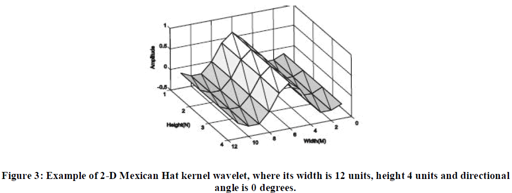
| Mexican Hat is equal to the second derivative of a Gaussian and it was widely used in computer vision to detect multi scale edges [7, 8]. Thus, we use 2-D Mexican Hat kernel whose sample is depicted in Figure 1. |
 |
 |
 |
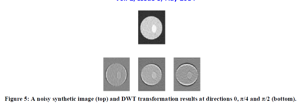
| From these examples it is clear that the kernels suppress all variations which are not parallel with their directions. Homogeneous regions result in grey color (Figure 2, bottom row). Also, the structures, e.g. isolated singularities along the line, create cones of large amplitude coefficients between locations of these singularities. On the other hand, singularity neighbors with the same directions as kernels are emphasized as black and white pixels and significantly differ from the back ground. The singularity is visible as zero crossing. The more the singularity direction corresponds with the operator orientation, the more intensive is the obtained response. However, them a in benefits of directional wavelet transform are: a) signal decomposition into four-dimensional space and b) capability of detecting the singularity lines. |
IV. DCT (DISCRETE COSINE TRANSFORM) |
| The discrete problem is so natural and almost inevitable, that it is really astonishing that the DCT was not discovered until 1974 [11]. Perhaps this time delay illustrates an underlying principle. Each continuous problem (differential equation) has many discrete approximations (difference equations). The discrete case has a new level of variety and complexity, often appearing in the boundary conditions. In fact, the original paper by Ahmed, Natarajan, and Rao [11] derived the DCT-2 basis as approximations to the eigenvectors of an important matrix, with entries δ j-k-.This is the covariance matrix for a useful class of signals. The number δ (near 1) measures the correlation between nearest neighbors. The true eigenvectors would give an optimal “Karhunen -Loeve basis" for compressing those signals. The simpler DCT vectors are close to optimal (and independent of δ).The four standard types of DCT are now studied directly from their basis vectors. The jth component of the kth basis vector is |
 |
| Those are the orthogonal columns of the four DCT matrices C 1,C 2, C 3, C 4, The matrix C 3, with top row 1/(2)1/2 (1,1,1,,,,1) is the transpose of C4. All columns of C 2, C 3, C 4 have length (N/2)1/2.The immediate goal is to prove orthogonality. |
V. MEASUREMENT PARAMETERS |
A. MSE |
| The average squared difference between the reference signal and distorted signal is called as the Mean squared error. It can be easily calculated by adding up the squared difference of pixel by pixel and dividing by the total pixel count [8]. Let mxn is a noise free monochrome image I, and K is defined as the noisy approximation .Then the mean square error between these two signals is defined as: |
 |
| B. PSNR |
| The ratio between the reference signal and the distortion signal of an image is called as the peak signal to noise ratio, given in decibels. In general, a higher PSNR value should correlate to a higher quality image. So PSNR is defined as: |
| PSNR= 10 log 10L2/MSE eq.11 |
| Here L reflects the the maximum possible pixel value of the image .If the K channel is encoded with a depth of 8-bit, then L = 2^8 - 1 = 255. PSNR is usually expressed in terms of the decibels scale .If a signal to noise ratio is high then the mean square error will be minimum. |
VI. CONCLUSION |
| Image enhancement is applied in every field where images are ought to be understood and analyzed. It offers a wide variety of approaches for modifying images to achieve visually acceptable images. The choice of techniques is a function of the specific task, image content, observer characteristics, and viewing conditions. Wavelet transform is capable of providing the time and frequency information simultaneously. The frequency and time information of a signal .But sometimes we cannot know what spectral component exists at any given time instant. The best we can do is to investigate that what spectral components exist at any given interval of time. DWT is a linear transformation that operates on a data vector whose length is an integer power of two, transforming it into a numerically different vector of the same length. DCT exploits interpixel redundancies to render excellent decorrelation for most natural images. |
References |
|