Keywords
|
| Flyback DC-DC converter, , BiDirectional, Class E converters, hybrid electric vehicles |
INTRODUCTION
|
| Power supplies, which are used extensively in industrial applications, are often required to meet all or most of the following requirements. |
| 1. Isolation between the source and the load. |
| 2. High power density for reduction of size and weight. |
| 3. Controlled direction of power flow. |
| 4. High conversion efficiency. |
| The normal dc-dc converters do not meet most of these requirements. The isolated converters like flyback and forward converters can meet the above requirements. |
| Power electronics is an enabling technology for the development of electric or hybrid electric vehicles. For both ac and dc motor drives used in electric and hybrid electric vehicles, the basic requirement for efficient control is that the power electronic circuit should be capable of handling bidirectional power flow, i.e., energy transfer should be possible from battery to motor during motoring mode and motor to battery during regeneration. Now, the need for a bidirectional power converter should be properly examined. A battery can be used as a dc bus if the motor is rated for that voltage level. Thus, bidirectional power flow is not a problem because of the bidirectional power-handling capacity of a standard two-level three-phase inverter and also sinking and sourcing capacity of the battery. However, the traction motor should be rated for higher voltage to achieve higher efficiency for a given power rating. Therefore, the dc bus voltage should be maintained high enough to match the motor voltage rating. This problem can be solved by connecting a number of batteries in series. However, if too many batteries are connected in series, then the volumetric efficiency of the battery comes down. Therefore, there is a need for a bidirectional converter which interfaces the lowvoltage battery with a high-voltage dc bus and maintains a bidirectional power flow. |
| We know that normally the motors are rated for higher voltages so that the current drawn will reduce and the efficiency of the drive will increases. But the battery voltages are normally low and which will not match with the motor voltage. There is a need for the interfacing device between battery and motor. For this a multiphase bi directional flyback converter is used in this project. Various types of dc dc converters and introduction of hybrid electric vehicles is given below. |
| DC-DC power converters are employed in a variety of applications, including power supplies for personal computers, office equipment, spacecraft power systems, laptop computers, and telecommunications equipment, as well as hybrid vehicle, fuel cell vehicle, renewable energy system. In the electric vehicle applications, an auxiliary energy storage battery absorbs the regenerated energy fed back by the electric machine. So that, bidirectional dc-dc converter is required to draw power from the auxiliary battery to boost the high-voltage bus during vehicle starting, accelerate and hill climbing With its ability to reverse the direction of the current flow, and thereby power, the bidirectional dc-dc converters are being increasingly used to achieve power transfer between two dc power sources in either direction. |
| The recently proposed topologies mostly use soft-switching techniques. [1] proposes a novel soft-switching topology for zeta–fly-back converter where as [2] proposes a bidirectional dc–dc converter topology with dual halfbridge topology which has the advantage over dual full-bridge topology in terms of reduced device count. [3] proposes a bidirectional fly-back dc–dc converter with ZCS. [4] proposes a bidirectional dc–dc converter with many interleaved buck stages for automotive application. Apart from multiphase operation, the power converter should also be able to interface multiple energy sources to the battery. [5-7] proposes a scheme where multiple energy sources and the battery are connected to the dc bus, and the dc bus works as a junction point for all energy transfer. |
II. LITERATURE SURVEY
|
| Power electronics is an enabling technology for the development of electric or hybrid electric vehicles. For both ac and dc motor drives used in electric and hybrid electric vehicles, the basic requirement for efficient control is that the power electronic circuit should be capable of handling bidirectional power flow, i.e., energy transfer should be possible from battery to motor during motoring mode and motor to battery during regeneration. Now, the need for a bidirectional power converter should be properly examined. A battery can be used as a dc bus if the motor is rated for that voltage level. Thus, bidirectional power flow is not a problem because of the bidirectional power-handling capacity of a standard two-level three-phase inverter and also sinking and sourcing capacity of the battery. However, the traction motor should be rated for higher voltage to achieve higher efficiency for a given power rating. Therefore, the dc bus voltage should be maintained high enough to match the motor voltage rating. This problem can be solved by connecting a number of batteries in series. However, if too many batteries are connected in series, then the volumetric efficiency of the battery comes down. Therefore, there is a need for a bidirectional converter which interfaces the lowvoltage battery with a high-voltage dc bus and maintains a bidirectional power flow. |
| [1] tells that with the increasing demand for environmentally friendlier and higher fuel economy vehicles, automotive companies are focusing on electric vehicles, hybrid electric vehicles (HEVs), plug-in hybrid electric vehicles (PHEVs), and fuel-cell vehicles. These vehicles would also enable meeting the demands for electrical power due to the increasing use of the electronic features to improve vehicle performance, fuel economy, emissions, passenger comfort, and safety. In electric vehicles, HEVs, PHEVs, and fuel-cell vehicles, the challenges are to achieve high efficiency, ruggedness, small sizes, and low costs in power converters and electric machines, as well as in associated electronics |
III. BI DIRECTIONAL DC-DC CONVERTERS
|
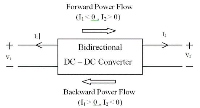
| Basic dc-dc converters such as buck and boost converters (and their derivatives) do not have bidirectional power flow capability. This limitation is due to the presence of diodes in their structure which prevents reverse current flow. In general, a unidirectional dc-dc converter can be turned into a bidirectional converter by replacing the diodes with a controllable switch in its structure . Most of the existing bidirectional dc-dc converters fall into the generic circuit structure illustrated in Figure 1.1, which is characterized by a current fed or voltage fed on one side. Based on the placement of the auxiliary energy storage, the bidirectional dc-dc converter can be categorized into buck and boost type. The buck type is to have energy storage placed on the high voltage side, and the boost type is to have it placed on the low voltage side. To realize the double sided power flow in bidirectional dc-dc converters, the switch cell should carry the current on both directions. It is usually implemented with a unidirectional semiconductor power switch such as power MOSFET (Metal-Oxide-Semiconductor-Field-Effect-Transistor) or IGBT (Insulated Gate Bipolar Transistor) in parallel with a diode; because the double sided current flow power switch is not available. |
IV. FLYBACK CONVERTERS
|
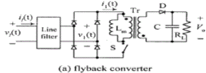
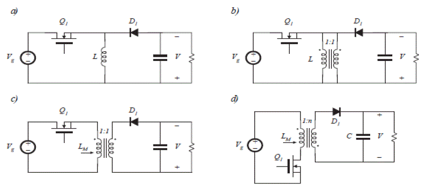
| The fly back converter is based on the buck-boost converter. Fig. 2 (a) depicts the basic buck-boost converter, with the switch realized using a MOSFET and diode. In Fig.2(b), the inductor winding is constructed using two wires, with a 1:1 turn’s ratio. |
| The basic function of the inductor is unchanged, and the parallel windings are equivalent to a single winding constructed of larger wire. In Fig.2 (c), the connections between the two windings are broken. One winding is used while the transistor Q1 conducts, while the other winding is used when diode D1 conducts. The total current in the two windings is unchanged from the circuit of Fig.2 (b); however, the current is now distributed between the windings differently. The magnetic fields inside the inductor in both cases are identical. Although the two-winding magnetic device is represented using the same symbol as the transformer, a more descriptive name is “two winding inductor”. This device is sometimes also called a “fly back transformer”. |
| Unlike the ideal transformer, current does not flow simultaneously in both windings of the fly back transformer. Figure 1.9 (d) illustrates the usual configuration of the fly back converter. The MOSFET source is connected to the primary-side ground, simplifying the gate drive circuit. The transformer polarity marks are reversed, to obtain a positive output voltage. An 1: n turns ratio is introduced; this allows better converter optimization |
V. PROPOSED CONCEPT
|
| The design of multiphase bi directional fly back converter Provides voltage boost with high gain and also provides bi directional power handling capability. It maintains features like obtaining high gain, wide load variations and lower output current ripple. This paper proposes a multi-power-port topology which is capable of handling multiple power sources and still maintains simplicity and features like obtaining high gain, wide load variations, lower output-current ripple, and capability of parallel-battery energy due to the modular structure. |
| The basic block diagram of the prototype of the multi power port (MPP) which is built for hybrid electric vehicle application is shown in Fig.3. The heart of the circuit is the bidirectional flyback dc–dc converter which provides voltage boost with high gain and bi directional power handling capability, because of providing multiple power port this circuit having more flexibility, which can be used for any other purpose by taking power from the port. Here power flows from battery to the dc link through bi directional fly back converter and also power flows from dc link to the battery through bi directional fly back converter. Single phase supply mains are considered for battery charging. Here if we observe the given proposed power schematic it allowing power from different sources and the same is supplying power to the different sources. this is feature is called the Multiple Power Port.(MPP). A four-phase converter is constructed using IGBT’s. |
| We know that in case of fly back converter ouput voltage |
| Vout = Vin * (D/1-D) |
| = Vin (0.75/1-0.75) |
| = 3 Vin |
| The output voltage is boosted by 3 times the input voltage. |
| During reverse power flow, active switches S2, S4, S6, and S8 get switching pulses of 25% duty cycle which are 90âÃâæ phase shifted to each other, as shown in Fig.3.3 (b). During this case |
| ouput voltage |
| Vout = Vin * (D/1-D) |
| = Vin (0.25/1-0.25) |
| = (1/3) Vin |
| The output voltage is step down by a factor 3. |
VI. SIMULINK MODEL
|
| The Simulink models for four phase bi directional flyback converter are shown in Fig 4. In order to verify the performance of the proposed converter, the specifications and circuit components are selected as Nominal battery voltage-60Volts, Switching frequency-20k.hz, Pulse width. forward switches-75% (%of period), backward switches- 25% (%of period) |
| IGBT Parameters: Internal resistance-1e-3, Snubber resistance-1e5, |
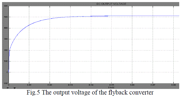
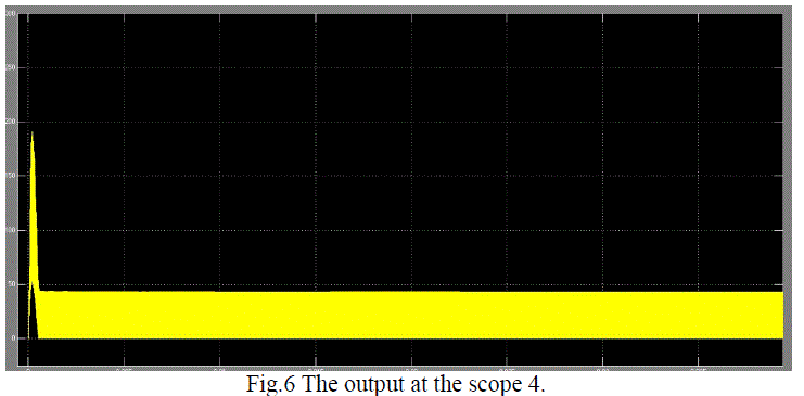
| Inductor parameters: Winding1 self impedance, R=0.0003, L=1.1e-05, Winding 2 self impedance Fig 5& 6 are out put plots of the model. |
VII. CONCLUSION
|
| This work proposes a four phase bidirectional flyback dc-dc converter which serves role of an MPP interface for electric and hybrid electric vehicle applications. In This paper the four phase bi-directional flyback Converter has been simulated and the results are verified. During simulation, it is observed that the voltage at the output terminals is nearly 500 volts. Also observed that the current at the time of starting is very high. This value of current is decreased by using a technique called soft start. With this technique the current value is normal at the time of starting. The features obtained by this converter is very much suited for hybrid electric vehicles. Finally this converter is applied to an 3-ph induction motor through an inverter. |
Figures at a glance
|
 |
 |
 |
| Figure 1 |
Figure 2 |
Figure 3 |
 |
 |
 |
| Figure 4 |
Figure 5 |
Figure 6 |
|
| |
References
|
- B.-R. Lin and F.-Y. Hsieh, “Soft-switching zeta–flyback converter with a buck–boost type of active clamp,” IEEE Trans. Ind. Electron., vol.54, no. 5, pp. 2813–2822, Oct. 2007.
- F. Z. Peng, H. Li, G.-J. Su, and J. S. Lawler, “A new ZVS bidirectional DC–DC converter for fuel cell and battery application,” IEEE Trans.Power Electron, vol. 19, no. 1, pp. 54–65, Jan. 2004.
- H. S.-H. Chung, W.-L. Cheung, and K. S. Tang, “A ZCS bidirectional flyback DC/DC converter,” IEEE Trans. Power Electron, vol. 19, no. 6,pp. 1426–2434, Nov. 2004.
- O. Garcia, P. Zumel, A. de Castro, and J. A. Cobos, “Automotive DC–DC bidirectional converter made with many interleaved buck stages,”IEEE Trans. Power Electron., vol. 21, no. 6, pp. 578–586, May 2006.
- L. Solero, A. Lidozzi, and J. A. Pomilio, “Design of multiple-input power converter for hybrid vehicles,” in Proc. IEEE APEC, vol. 2, pp.1145–1151.
- M. Michon, J. L. Duarte, and M. Hendrix, “A three port bi-directional converter for hybrid fuel cell systems,” in Proc. IEEE PESC, Aachen,Germany, Jun. 2004, pp. 4736–4742.
- H. Tao, A. Kotsopoulos, J. L. Duarte, and M. A. M. Hendrix, “Family of multiport bidirectional DC–DC converters,” Proc. Inst. Elect. Eng.—Electr. Power Appl., vol. 153, no. 3, pp. 451–458, May 2006.
|