Keywords
|
| HV, CSM, contour points, fictitious charges, electric field |
INTRODUCTION
|
| Physical systems are so complex that the analytical solution of Laplace’s and Poisson’s equation is very difficult. Hence two numerical methods had been introduced to find electric field distributions. The first method is based on the difference technique employing Laplace's and Poisson's equations in the space where the field is to be determined [1]. This is done by dividing the whole region of interest into small meshes. The second approach to the computation of fields is to integrate Laplace's or Poisson's equation either by employing discrete charges or by discretising the electrode surface into subsections with charges. Under this approach of electric field calculation falls the Charge Simulation Method (CSM). In this paper we have made a comparative analysis of the electric field calculated in CSM and Analytical method for the basic charge configurations |
| Charge simulation method [2] has been used for many high voltage problems. This method works by replacing the distributed charge of conductors as well as the polarization charges on the dielectric interfaces by a large number of fictitious discrete charges [3]. In the CSM, the actual electric field is simulated with a field formed by a number of discrete charges which are placed outside of the region where the field solution is desired. An advantage is that it can be applied to three dimensional field problems without axial symmetry. |
II. REVIEW
|
| This section is aimed at providing an insight into the different numerical methods of electric field calculation. Numerical methods are used to determine the electric field distribution for complex geometries, where it is cumbersome and expensive to use analytical techniques or run laboratory tests. There are two different categories of numerical methods: The domain methods and the boundary methods [5]. Domain methods make use of differential equations whereas boundary methods make use of integral equations in their solver. The different domain methods are Finite Element Method (FEM) and Finite Difference Method (FDM); while the boundary methods include Charge Simulation Method (CSM) and Boundary Element Method (BEM). Finite difference method (FDM) is the oldest technique in the field computations that was introduced by Gauss. Then Boltzmann published it in his notes in 1892. The principle of Finite Difference Method (FDM) [6] is to discretize the entire region under study and solve for unknown potentials, a set of coupled simultaneous linear equations which approximate Laplace’s or Poisson’s equation. Among the various numerical techniques, the finite element method (FEM) has a dominant position because it is versatile, having a strong interchangeability and can be incorporated into standard programs [5].To apply FEM [4], the field region is to be discretized by a grid of so-called finite elements. The work presented here makes use of the CSM.The fundamentals of CSM and calculations of electric field intensities for models having rotational symmetry have been presented by Singer, Steinbigler and Weiss [1]. |
III. BASIC PRINCIPLE OF CSM
|
| The basic principle of the CSM is very simple. If several discrete charges of any type (point, line or ring, for instance) are present in a region, the electrostatic potential at the ith contour point can be found by summation of the potentials resulting from the individual fictitious charges (j) as long as the point does not reside on any one of the charges [4] . Let Qj be a number of n individual charges and Vi be the potential at any point within the space. According to superposition principle- |
 (1) (1) |
| where Pij, are the ‘potential’ coefficients which can be evaluated analytically for any types of charges by solving Laplace's or Poisson’s equations . As soon as the fictitious charges are determined, the potential and the field intensity at any point outside the electrodes can be calculated. As soon as an adequate charge system [3] has been developed, the potential and field at any point outside the electrodes can be calculated. Whereas the potential is found by Equation (1), the field stress is calculated by superposition of magnitudes of various directional components. For example, for Cartesian coordinate system, the net field E, at ith contour point, is given by— |
 (2) (2) |
| where (fij)x , (fij)y and (fij)z are the ‘field intensity’ or field coefficients and ax , ay and az are unit vectors in the x, y and z directions, respectively. |
| The successful application of the CSM requires a proper choice of the types of fictitious charges. Point and line charges of finite length and ring charges have been used [3]. In general, the choice of type of fictitious charge to be used depends upon the complexity of the physical system and the available computational facilities. In practice, most of the HV systems can be successfully simulated by using point, line and ring charges or a suitable combination of these charges. The correct choice of the type of fictitious charges is very important, especially with respect to the realized accuracy. Also, it is very important to determine the position of fictitious charges. |
IV. RESULTS AND DISCUSSION
|
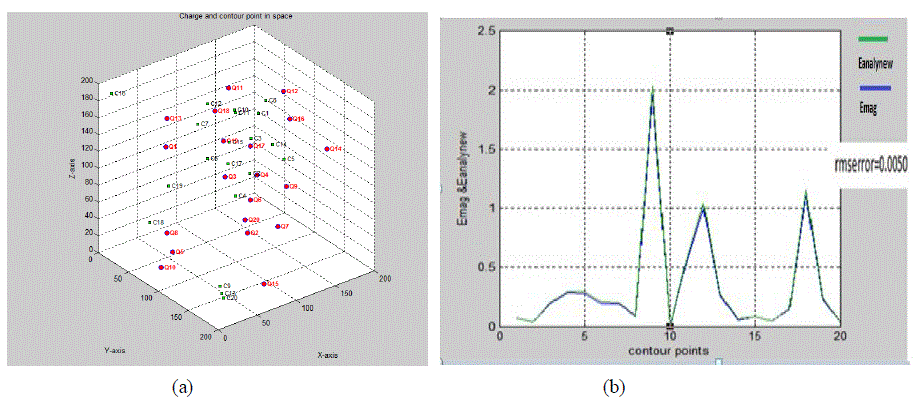
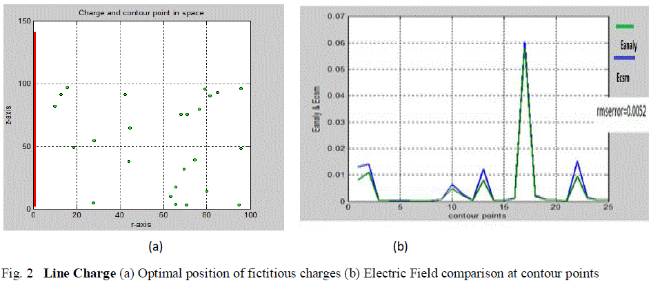
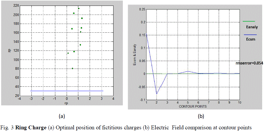
| For electric field calculation due to point charge, following the conventional CSM, first the charge system is developed by determining the optimal positions of the fictitious point charges and contour points which is shown in Fig. 1(a). Once the charge system has been developed, the potential coefficients can be calculated by solving the Laplace’s or Poisson’s equations for point charges. The potential and electric field intensity can be easily calculated as given in equation (1) & (2). Taking into account random contour point positions and point charge positions, the electric field using CSM (Emag) has been calculated at different positions of the contour points and has been compared with the electric field as calculated with the analytical method (Eanalynew) for point charge by formulating suitable MATLAB programs for these which is shown in Fig.1(b) and Table 1. Similarly for calculation of electric field due to line charge and ring charge by CSM, random contour point positions and fictitious charge positions are taken into account by formulating suitable MATLAB programs for these. By randomly varying the positions of the contour points and simulation charges, the optimal positions of the fictitious charges is determined which is shown in Fig. 2(a) for line charge and in Fig.3 (a) for ring charge. The comparison of the electric field calculated at the contour points by CSM (Ecsm) and analytical method (Eanaly) is shown in Fig 2(b) for line charge and in Fig 3(b) for ring charge. The electric field computed at the contour points for line charge and ring charge are shown in Table 2 and Table 3 respectively. |
| The error in the CSM depends upon the types, numbers as well as locations of simulation charges, the locations of contour points and the complexities of the profiles of electrodes as well as dielectrics. Calculations are repeated by changing one or several of the following parameters [4]: |
| 1. The number of simulation charges |
| 2. The locations of simulation charges |
| 3. The types of simulation charges |
| 4. The locations of contour points |
V.CONCLUSION
|
| In this paper, the contour point and fictitious charge positions have been randomly varied and various cases have been examined. After determining the optimal positions of the fictitious charges, comparison between the electric field calculated by CSM and calculated by analytical method has been done. For point charge an rmserror of 0.005 was found and for line charge it was found to be 0.0052 and for ring charge it was found to be 0.054. The validation of the CSM based electric field calculation using MATLAB has been done by comparing the results with the analytical method. The obtained results shows that the precision of the solution depends on the number and positions of the FCs. Higher precision can be achieved by increasing the number of FCs. The number of FCs can’t be too large because the system of equations could be ill conditioned. Thus, these basic charge configurations can be used for the discretisation of complex electrode geometries to compute the electric field for a single or a multi-dielectric medium by CSM. |
Tables at a glance
|
|
|
| |
Figures at a glance
|
 |
 |
 |
| Figure 1 |
Figure 2 |
Figure 3 |
|
| |
References
|
- H. Singer, H. Steinbigler and P. Weiss, “A charge simulation method for the calculation of high voltage fields”, IEEE Trans. PAS, Vol. 93,pp. 1660-1668, 1974.
- P. K. Mukherjee and C. K. Roy, “Computations of fields in and around insulators by fictitious point charges”, IEEE Trans. ElectricaInsulation, Vol. 13, No. 1, pp. 24-31,1978.
- N. H Malik,“A review of the charge simulation method and its application”, IEEE Trans. On Electrical Insulation, Vol. 24(1), pp. 3-20, 1989.
- E. Kuffel and W. S. Zaengl, High Voltage Engineering Fundamentals, Pergamon Press, Oxford, 2001
- M. V. K. Chari, G. Bedrosian and I. D. Angelo, “Finite element applications in electrical engineering”, IEEE Trans. Magnetics, Vol.29,pp. 1306±1314, 1993.
- G.D.Smith, Numerical solution of partial differential equations: finite difference methods, 2nd edition : oxford : Clarendon, 1978.
- P. B. Zou, Numerical Analysis of Electromagnetic Fields, Springer-Verlag, Berlin, 1993.
- S.Chakravorti’s Lecture in NERIST Course, “Electric Field Calculation by Charge Simulation Method”, September, 2012
- Xiaoming Liu, Yundong Cao, and Erzhi Wang “Numerical Simulation of Electric Field With Open Boundary Using Intelligent Optimum
- Charge Simulation Method”, IEEE Transactions on Magnetics, vol. 42, no. 4, pp.1159-1162, April,2006.Ryo Nishimura , Katsumi Nishimori and Naganori Ishihara, “Determining the arrangement of fictitious charges in charge simulation methodusing genetic algorithms”, Journal of Electrostatics,Volume 49, Issues 1–2, Page 95–105, May 2000.
- Tanushri Doshi, “Performance Analysis of Composite Insulators up to 1200 kV ac using Electric Field Calculations” , A Thesis Presented inPartial Fulfillment of the requirements for the Degree of Master of Science, ARIZONA STATE UNIVERSITY, December 2010.
- E.S.Kolechitsky, “Calculation of Electric Field of high voltage installations”, Energoatom press, Moscow,pp.46-49,1983.
- Xiaoming Liu, Yundong Cao, and Erzhi Wang, “Numerical Simulation of Electric Field With Open Boundary Using Intelligent OptimumCharge Simulation Method”, IEEE Transactions on Magnetics, vol. 42, no. 4, pp.1159-1162, April,2006
- H. Brauer, “Computation of electromagnetic fields using integral methods”, International PhD - Seminar, Budva, Serbia and Montenegro,pp. 201-212,September 2004.
- S. Chakravorty, “Charge Simulation Method: a critical overview", Ie (I) journal-el, Vol. 78, pp. 210-214, March 1998.
|