Keywords
|
| Digital Signal Processing, Least Mean Square (LMS), System Generator, Accel DSP, SPARTAN -3 XC3S500 FG320 -5. |
INTRODUCTION
|
| The main purpose of every filter is to acquire useful information from a signal with noise. During data transmission the data gets corrupted by various noises. These noises are removed effectively by filters. A fixed normal filter is designed knowing the statistics of the two signals: the desired information and the noise. An adaptive filter [1] auto sets continuously to the environment changes through the use of recursive algorithms, and is used when statistics and temporal changes of the signal and the noise are preliminarily unknown. |
| An adaptive discrete filter accepts en enter u(n) and produces an output y(n) due a convolution with the filter weight wn. A reference wished signal d(n), is compared at the output to obtain an error estimate e(n). This error signal is used to increasingly adjust the filter weight for the next interval of time. There are two major algorithms used to adjust the weights on run for these adaptive filters and they are the LMS (Least Mean Square) and the RLS (Recursive Least Square). |
| In this work it is described the implementation of the LMS algorithm which is more of a basic algorithm among the two and extend the work in the future for the implementation of other advanced algorithms over an FPGA Spartan 3 from Xilinx, using Matlab 7 and System Generator tools due to its Simplicity in implementation and Stable and robust performance against different signal conditions of the algorithm. |
LEAST MEAN SQUARE ALGORITHM
|
| The LMS algorithm was created by Widrow and Hoff in 1960 to be used in the training of neural networks. It uses a rough gradient approximation, and seeks the wished weight vector [2]. This process is used to find the weight vectors for training the ALC (Adaline) [3]. The learning rules can be incorporate to the same device that therefore can be auto adapted as there are presented the wished inputs and outputs. The weight vectors values are changed as every combination. |
| Input-output is processed. This goes on until the ALC gives the correct outputs. This is a truly training process since there is not necessary to clearly calculate the weight vector value. The input signal is the sum of a desired signal d(n) and interfering noise v(n). |
 |
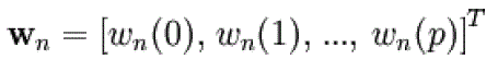
| The variable filter has a Finite Impulse Response (FIR) structure. For such structures the impulse response is equal to the filter coefficients. The coefficients for a filter of order p are defined as |
 |
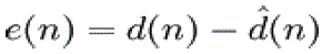
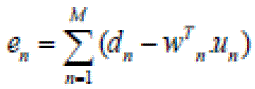
| The error signal or cost function is the difference between the desired and the estimated signal. |
 |
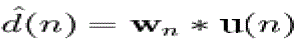
| The variable filter estimates the desired signal by convolving the input signal with the impulse response. In vector notation this is expressed as |
 |
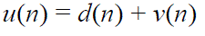
| u(n) is the input signal vector. Moreover, the variable filter updates the filter coefficients at every time instant based on the below expression |
 |
| Where is a correction factor for the filter coefficients The adaptive algorithm generates this correction factor based on the input and error signals [11]. |
IMPLEMENTATION IN MATLAB
|
| The LMS Algorithm had been developed in Matlab Simulink with the Xilinx tools: System Generator. |
| An input signal containing the information is generated; this passes through a channel. The channel may introduce random noise to the signal transmitted through the channel. |
| So, an adaptive filter with one input to the filter as the signal with noise and the other input being the desired signal. Each time the weights are updated based on cost function specified. |
| To develop the training algorithm of the adaptive filter, it is necessary to perform some changes. The signal must pass through a gateway that changes the float point to fixed point to work with System Generator. |
| Then the LMS algorithm is implemented, and the actual weights of the recursive filter are obtained. With the purpose of taking different samples of the input signal in the time, u(n) n = 1, 2, 3, 4…, some delays are used. |
| Then this signal is multiplied by the error resulting from the difference between the wished signal and the actual one of the filter and by a constant 2μ, to this product it is added the previous weight value to obtain the actual weight value. |
| The filter output results from the product between the input signal u(n) and the actual weight value w(n). This is described in the following expressions: |
 |
| Finally the input signal, the signal with noise, the signal, the filter output and at last the error, are viewed as the Matlab results shown in Fig 1 to 4. |
| The algorithm on the similar way is implemented for the audio signals where in the two input signals of the adaptive filters are one being the original audio signal i.e., the desired signal d(n) as in Fig 5. |
| The algorithm is implemented for the audio signals where in the two input signals of the adaptive filters are one being the original audio signal in above Fig 5 while the other being the signal corrupted by random noise shown in Fig 6. |
| The filters adjusts the weights based on the step size and as time goes on, it is observed that the signal at the filter output is close to the wished one and the error signal e(n) is reduced. This due to system stabilization as the error diminishes as time increases, as it is shown in Figure 7. |
IMPLEMENTATION AS SIMULINK BLOCK
|
| The Matlab code is the converted to a Simulink block as shown in Fig.8 using the AccelDSP software. AccelDSP is a synthesis tool that allows one to transform a MATLAB floating-point design into a hardware module that can be implemented in a Xilinx FPGA. |
| The AccelDSP Synthesis Tool features an easy-to-use Graphical User Interface that controls an integrated environment with other design tools such as MATLAB, Xilinx ISE tools, and other industry- standard HDL simulators and logic synthesizers. |
| The software initially generates a fixed point from a floating point [10]. The generated floating points are then verified and the RTL is generated for the desired target which is for the family Spartan 3E with XC3S500E for the package FG320 with speed -5 with maximum I/O’s as 232 and frequency as 100MHz and the required number of I/O’s are calculate by the simulator. Finally the RTL is verified for the simulation tool of ISE Simulator in fig.9 with target language as VHDL as to be implemented in FPGA and finally generating the system generator producing the block for the given code and is added as a block in the Simulink library[12]. |
IMPLEMENTATION IN FPGA
|
| Before loading the software in the FPGA, with the System Generator icon, a block called JTAG is created, this enables the passing of the program to the card through a cable. |
| The JTAG block obtained is tested using the same procedure as that adapted for the Simulink block to check for the output match between the two results. |
CONCLUSION
|
| For obtain the best weight vector in the LMS algorithm, it is necessary to drop or at least to minimize the difference between the wished output and the real one for all the input vectors. The approximation used in this report consists in minimizing the mean square error for the input values sets. |
| Once the LMS algorithm had been implemented, one can easily realize that it is very simple and easy to apply since it no requires calculations or complex measures. The algorithm provides convergence and stability although there is a noise or error excess as result of using approximations to the gradient. |
| The future work would be implement more complex adaptive algorithms like RLS algorithm which has a better convergence but will have a complex implementation. |
Figures at a glance
|
 |
 |
 |
 |
 |
| Figure 1 |
Figure 2 |
Figure 3 |
Figure 4 |
Figure 5 |
 |
 |
 |
 |
 |
| Figure 6 |
Figure 7 |
Figure 8 |
Figure 9 |
Figure 10 |
|
References
|
- Joseph Petrone, Adaptive Filter Architectures, Florida, June 2004.
- B. Widrow and S.D. Stearns, Adaptive Signal Processing, Prentice Hall, Englewood Cliffs, NJ, 1985.
- B. Widrow, Adaline: Smarter than Sweet, Stanford Today, Autumn 1963.
- B. FarhangBoroujeny, Adaptive Filter Theory and applications, Wiley, Singapore, 1999.
- B. Widrow and M.A. Lehr, ``Adaptive Neural Networks and their Applications,'' International Journal of Intelligent Systems, 8(4):453-507, April1993.6
- http://plaza.ufl.edu/badavis/EEL6502_Project_1.html
- B. Widrow, J.R. Glover, Jr., J.M. McCool, J. Kaunitz, C.S. Williams, R.H. Hearn, J.R. Zeidler, E. Dong, Jr., and R.C. Goodlin, ``Adaptive NoiseCancelling: Principles and Applications,'' Proceedings of the IEEE, 63(12):1692-1716, December 1975.
- TianLan, Jinlin Zhang, "FPGA Implementation of an Adaptive Noise Canceller," isip, pp.553-558, 2008 International Symposiums onInformation Processing, 2008.
- C. Shi, R. W. Brodersen, “A Tutorial of Floating-point to Fixed-point Conversion Tool on a BPSK Communication System”, March 27, 2004.
- Changchun Shi, Floating-point to fixed-point conversion, May, 2004, Ph. D Thesis, Department of EECS, University of California, Berkeley
- Garimamalik, Amandeep Singh Sappal, “Adaptive Equalization Algorithms:An Overview”, International Journal of Advanced ComputerScience and Applications, March 2011.
- Jitendra Kumar Das, K. K. Mahapatra, “design of adaptive hearing aid algorithm using booth Wallace tree multiplier”, CSC Journal, December2010.
|