Keywords
|
| B&R Automation Studio HMI, VNC, PLC, VNC Viewer |
INTRODUCTION
|
| Visualization aims at a better Human-machine interaction. Any automation system is said to be blind without HMI. HMI gives the ability to the operator, and the management to view the plant in real time. Add to that the ability to have alarm management that can warn the operator of a problem. It can even log and print all the alarms in real time, which can help the management to improve the production and efficiency. Human Machine Interface can display texts, pictures, bar graphs, bitmap and animated pictures. More importantly it can also display System messages, reports, alarms, trends and manipulate string values and calculate Boolean operations and more complex math operations. PLC device is well-adopted to a range of almost all types of automation tasks. PLC-program becomes underlying component for modern manufacturing. Inefficiency in generating the controlling code in the manufacturing plant may cause huge down time and ramp-up times [1]. Hence, auto generation of PLC program using rapid modeling and compiling tools to generate IEC standard PLC program is an efficient method to reduce the PLC development time. |
| The realization of MATLAB/Simulink models starts with the automatic code generation. With this product “B&R Automation Target for Simulink” B&R Industrial Automation provides a tool with highest level of integration with model based design software Math works. This tool allows testing and implementing MATLAB/Simulink models on the PLC hardware. Thus, the manual programming efforts are reduced to a minimum and in many cases actually not required [3] |
| In this paper the Section II explains Methodology [4], Section III deals with detailed algorithm for integrating simulink model and B&R target PLC Section IV gives verification & validation of results. Section V is conclusion with an acknowledgement |
METHODOLOGY
|
| The module created in Simulink is automatically translated using Real-Time Workshop and Real-Time Workshop Embedded Coder (optional) into the optimal language for the B&R target system To generate Automatic code for PLC the block diagram described in this paper employs, designing of mathematical model using formulas. Later, implementation of mathematical model of a process using MATLAB Simulink is build with the help of simulink library blocks. The next step is to be carried out in an Automation Studio environment. In this we have to build model with the help of B&R blocks which are available in B&R toolbox in a simulink library. After doing configuration settings we are able to translate simulink models into a PLC code on a click of button. As the automatic code is generated in Automation Studio the HMI is developed. Visualization with Automation Studio is developed for 1. Local Display 2. VNC Visualization 3.Terminal Visualization. |
| Visualization Online connection via various interfaces |
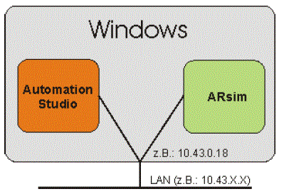
| 1. Connection via LOCAL HOST: When an "unconfigured" ARsim (default settings) is started, the connection is possible. This corresponds to the default Automation Studio Ethernet settings for ARsim. |
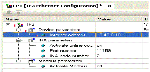
| 2. Connecting via physical interface on the PC: If the Ethernet interface is configured in Automation Studio for ARsim, a LAN connection is possible. The following steps are necessary: |
| ïÃâ÷ Set the IP address in the project |
| ïÃâ÷ Transfer the project to the target system |
| ïÃâ÷ Change the online connection to the IP address configured in the project (/REPO=11160) |
| 3. External TCP/IP connection: If Automation Runtime runs on a PC other than the ARsim, a connection can be established via LAN / Internet on the ARsim Ethernet interface. |
| For this variant, the IP address and the remote port of the ARsim must be specified in the Ethernet online connection. Example a PC with Automation Studio and IP address 172.16.2.10 & PC with ARsim and IP address 172.16.2.55 |
| TCP/IP settings: The setting for Source address1 ARsim: 1 – 255: Virtual node number of the system where Automation Studio is installed. If two PCs have simultaneous connections to the same target system, then both of the PCs must have different source addresses configured in Automation Studio. Then enter destination address2:ARsim2.This entry 2 should not be modified in the ARsim communication. Specify an IP address. In this case, the IP address of the ARsim PC is specified as 172.16.2.55. |
Virtual Network Computing (VNC)
|
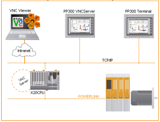
| VNC technology uses standard communication methods to allow a system to be controlled remotely from a desktop or laptop. TCP/IP is used for the network, which means nearly any Internet-capable network connection can be used. Keyboard entries and mouse operations are transferred from the VNC client to the VNC server. Screen content is transferred from the VNC server to the VNC client. With VNC main office visualization without additional work. Resolution from QVGA to SXGA is possible. Password protected access. It also supports mobile Panel 40/50. It is platform-independent implementation of the VNC viewer for all standard operating systems. The Remote Frame Buffer (RFB) protocol is documented and has been implemented in Visual Components on the server side. |
ALGORITHM FOR VNC VISUALIZATION PROJECT DEVELOPMENT
|
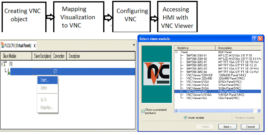
| This section describes the procedure for developing a VNC visualization project and the various configuration options. Inserting a VNC object: A VNC object is inserted in the physical view of the active configuration as a Virtual panel. In the ARwin simulation the VNC object is inserted under Virtual IF. Mapping the visualization to a VNC object: The visualization object can be mapped to a VNC object in the physical view of the active configuration. Configuring the VNC object: The VNC object is configured in the physical view of the active configuration on the VNC server object. |
| Inserting a VNC object: A VNC object is inserted in the physical view of the active configuration as a Virtual panel. In the ARwin simulation the VNC object is inserted under Virtual IF. Mapping the visualization to a VNC object: The visualization object can be mapped to a VNC object in the physical view of the active configuration. Configuring the VNC object: The VNC object is configured in the physical view of the active configuration on the VNC server object. |
| Step I: Creating a VNC object: A VNC object (virtual panel object) can be inserted in the physical view of the Automation Studio project. The visualization object is assigned to a VNC object in the VC mapping as either an independent VNC visualization (master) or an existing visualization (slave).Inserting VNC visualization: A VNC visualization can be inserted in the physical view of Automation Studio using the menu item Open - Virtual Panels or the option Open Virtual Panels in the shortcut menu of the control hardware. |
| In this dialog box, the Insert option in the shortcut menu for a virtual interface (IFx) is used to select a VNC object with the desired resolution. Assigning a visualization object : The assignment of the visualization object to a VNC object takes place in the VC Mapping editor. Automation Studio must already contain one or more visualization objects. |
| Module address: The module address displays the physical module address to which the visualization objects or keyboard configuration is connected. Master The module address of the master hardware can optionally be entered in the Master column. Once a master has been specified, this hardware cannot be assigned its own visualization object in the VC Object Name column. A master can only be assigned to hardware that can function as a slave. For example, with VNC or keyboard connections.VC object name: The visualization object to be displayed on this hardware during runtime is entered in the VC Object Name column. This column only contains Visual Components objects that were mapped in the configuration from the logical view and which match the resolution (Visual Components VC4 objects) or the hardware specified when they were created (Visual Components VC3 objects).Key mapping file:Key mapping files are necessary for assigning the hardware keys to the virtual keys of Visual Components VC4 objects. As a result, this column only has an effect if a Visual Components VC4 object has been assigned to this hardware and the hardware contains keys. |
Step III: VNC Configuration
|
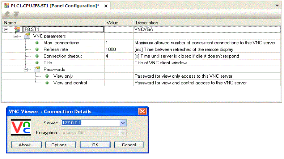
| The VNC object is configured in the Panel Configuration view. |
| Maximum connections: Maximum number of simultaneously allowed VNC connections to this VNC object (1- 4).Refresh rate: Time [ms] it takes the VNC viewer display to update (100-1000).Connection timeout: Time [s] until server is closed if client doesn´t respond. If the VNC application uses a slow Ethernet connection (e.g. SLIP or PPP via modem), connection problems will occur if the default timeout of 4000 ms is not sufficient. Title: Optional title of VNC client window. Passwords: View only Password that must be entered when starting the VNC viewer in order to display the visualization. This password does not allow the user to perform any operations in the visualization. View and control: Password that must be entered when starting the VNC viewer in order to display and operate the visualization. |
VERIFICATION & VALIDATION OF RESULT
|
| VNC connection to PC based Simulation Runtime |
| A connection to the PC based Simulation Runtime can be established using any VNC viewer. Start the VNC viewer: After starting the VNC viewer, enter the IP address of the PC based Simulation Runtime - 127.0.0.1. Screen shot of VNC viewer dialog box is shown. |
| If the dialog box is confirmed with OK, the password for operating the visualization must then be entered. The password for operation is the character c. If this dialog box is confirmed with OK, the visualization is displayed in the VNC viewer. |
| Test in the Visualization Application: |
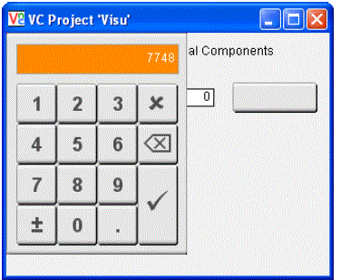
| The visualization is displayed as follows after the VNC Viewer is started. If you click on the input field, a value can be entered in the NumPad. Once you confirm by clicking on Enter, the value is displayed in the input and output field. |
CONCLUSION
|
| The main aim of this project was to communicate with PLC and MATLAB/SIMULINK by developing an interactive touch screen HMI. The visualization has been developed with Automation studio which can be accessed remotely also with the help of VNC viewer. With the high quality graphics for realistic representations of machinery and processes gives the operator and the management a very realistic view of the plant. Viewing alarms will help the operator to locate and react faster to any malfunction of any anomalies. Trends (Real Time / Historical) are very useful with PID's. Reduce the cost of hardware. An good HMI can replace hundreds of Push buttons, selectors, Lights and so on. As a result less consoles and panels and definitely less cables all over the plant. The HMI can communicate with many different brands of PLC's as a Serial Port, Data Highway Plus, Remote I/O, Ethernet (TCP/IP), and DDE - Dynamic Data Exchange (DDE) also. |
ACKNOWLEDGMENT
|
| The authors would like to express their gratitude to B&R Automation Industrial Pvt. Ltd. for sponsoring this work as well as providing the valuable guidance and support to make it possible to experiment it practically. |
Figures at a glance
|
 |
 |
 |
 |
 |
| Figure 1 |
Figure 2 |
Figure 3 |
Figure 4 |
Figure 5 |
 |
 |
 |
 |
| Figure 6 |
Figure 7 |
Figure 8 |
Figure 9 |
|
References
|
- .Schiop, L., Gaiceanu, Mathematical Modelling Of Color Mixing Process And PLC Control Implementation By Using Human Machine Interface,Electrical& Electronics Engineering (ISEEE),3rd International Symposium on , vol., no., pp.165-170,16-18.
- M. Sultan, M., S. Shah, A., C.O.David, „Controllers optimization for a fluid mixing system using metamodelling approachâÃâ¬ÃŸ, International Journal of Simulation Modelling,(2009) ISSN 1726-4529, Volume 8. pp.48-60.
- 3. James M. Ali, M.S. Abdullah, S.S. Kasno,Fuzzy Logic Controller Optimization Using Metamodeling Technique For A Fluid Mixing System,Mechatronics and Automation,ICMA 2008.IEEE International Conference on, ISBN: 978-1-4244-2631-7, 5-8 Aug.,pp 947 – 953.
- B&R Automation Studio Target for Simulink TM140 Manual http://www.br-automation.com
- B. Mulman, T. Devinder, and W. Gi-Nam., Generation of PLC Ladder Diagram Using Modular Structure. International Conference on Computational Intelligence for Modelling, Vienna, pp. 1194-1198,Oct 2008.
- M.Fabian, K. kesson, and D. Spensieri. Automatic Model Generation and PLC-Code Implementation For Interlocking Policies In Industrial Robot Cells. Proc. of Control Engineering Practice,11, pp. 1416-1426(1), 2007.
- Kurt W Leucht,Glenn S Semmel,Automated Translation of Safety Critical Application Software Specification into PLC Ladder Logic, Aerospace Conference,2008 IEEE.
- PetterFalkman, Erik Helander, MikaelAndersson, Automatic Generation: A way of Ensuring PLC and HMI Standards, Aerospace Conference, IEEE ETFA'2011.
|