Keywords
|
| Discrete wavelet transform, Fractal image compression, Set partitioning in hierarchical trees. |
I.INTRODUCTION
|
| This Lossy compression schemes such as JPEG achieve most of their data reduction by eliminating spatial redundancy within the images [2]. Fractal image compression [1] also takes advantage of redundancy in scale, but its operating principles are very different from those of transform coders. Images are not stored as a set of quantized transform coefficients, but instead as fixed points of maps on the plane. The theory of Iterated Function Systems (IFS) [3] motivates a broad class fractal compression schemes. In Fractal Image Coding [4] the image to be encoded is partitioned into non-overlapping range blocks. For each of these range blocks a larger domain block of the same image has to be determined such that a contractive (geometrical and luminance) transformations of this block is a good approximation of the range block. At the decoder all transformations are iteratively applied to an arbitrary initial image which then converges to the fractal approximation of the image [3] Fractal Coding relies on the existence of self similarities within the image. As “fractal self similarity” can only be found in certain regions of natural images, fractal coding fails for non-fractal image contents [4]. In its original form fractal coding suffered from low coding efficiency, difficulties to obtain high quality encoding of images and blocking artefacts at low bit rates and exhaustive inherent coding time. Blocking artefacts can be avoided, if fractal coding is performed in the wavelet domain. |
| Fractal coding assumes that all wavelet sub trees that make up an image can be described by other wavelet sub trees from coarser scales. In the image compression field, high compression is needed without losing the quality of an image [1]. There is a need for better compression method than the existing one. The combination of various methods may give |
| better results. So, in this work the Non Iteration Fractal Image Compression method called WFC and modified SPIHT (Said and Pearlman, 1996) are combined to produce a new method. WFC is also giving a better image quality and good compression ratio and also it is faster. Combining both methods will surely give better image quality and compression ratio than the pure iteration free image compression method and SPIHT. Fractal and wavelet algorithms offer significant side benefits beyond high compression ratios. One feature of progressive transformation cuts decompression time for lower-resolution image. Fractal and wavelet methods are also resolution-independent, enabling the same encoded file to be viewed at multiple resolutions . A means of exploiting the similarities between the wavelet and fractal transforms has been suggested. This method centers on coding the image by the fractal transform normally in mapping a domain block onto a range block in the spatial domain that frequency information at one level of the wavelet decomposition would correspond well with the frequency information of the range block at the previous level of decomposition, assuming dyadic fractal contractions . An improved coding efficiency is achieved compared to conventional fractal coders.The number of bits required for storing gray scale offset and contraction, spatial offset, the maximum and minimum size of range blocks and the acceptable error tolerance in comparison of domain blocks and range blocks are the different parameters, which are used to vary the compression ratios of the fractal coder. |
II. FRACTAL IMAGE COMPRESSION
|
| A. Basics of fractal |
| The image compression scheme describe later can be said to be fractal in several senses. The scheme will encode an image as a collection of transforms that are very similar to the copy machine metaphor. Just as the fern has detail at every scale, so does the image reconstructed from the transforms. The decoded image has no natural size, it can be decoded at any size. The extra detail needed for decoding at larger sizes is generated automatically by the encoding transforms. One may wonder if this detail is “real”; we could decode an image of a person increasing the size with each iteration, and eventually see skin cells or perhaps atoms. The answer is, of course, no. The detail is not at all related to the actual detail present when the image was digitized; it is just the product of the encoding transforms which originally only encoded the large-scale features. However, in some cases the detail is realistic at low magnifications, and this can be useful in Security and Medical Imaging applications. |
| B. Iteration function system |
| Iterated Function Systems set the foundation for Fractal Image Compression. The basic idea of an Iterated Function System is to create a finite set of contraction mappings, written as affine transformations, based on what image one desires to create. If these mappings are contractive, applying the IFS to a seed image will eventually produce an attractor of that map. It does not matter what the seed image is for the mappings, the same fixed point will be produced regardless. Let us consider the case of the photocopying machine which we saw earlier. Suppose we were to feed the output of this machine back as input and continue the process iteratively. We can find that all the output images seem to be converging back to the same output image and also that the final image is not changed by the process. We all this image the attractor for the copying machine some of the output shown in below fig. |
| The output images is to the Sierpinski triangle this final image is called attractor. Any initial image will be transformed to the attractor if we repeatedly run the machine. The attractor for this machine is always the same image without regardless of the initial image. This feature is one of the keys to the fractal image compression. Because the copying machine reduces the input image the copies of the initial image will be reduced to a point as we repeatedly feed the output back as input there will be more and more copies but the copies at each stage get smaller and smaller. So the initial image doesn’t affect the final attractor ; in fact, it is only the position and orientation of the copies that determines what the final image will look like. |
| The final result is determined by the way the input image is transformed , we only describe these transformations. Different transformations lead to different attractors with the technical limitation that the images must be contractive; i.e, a given transformation applied to any point in the input image must bring them closer in the copy. This technical condition is very natural since if the points in the copy were to be spread out the attractor might have to be of infinite size. A common feature of these attractors thus formed is that in the position of each of these images of the original square there is a transformed copy of the whole image. Thus the images thus formed are all fractals. This method of creating fractals was put forward by John Hutchinson. M. Barnsley suggested that perhaps storing images as collections of transformations could lead to image compression. The complex figure of a fern is generated from just four affine transforms. Each This is because of the magnification produced. Standard image compression methods can be evaluated using their compression ratios : the ratio of the memory required to store an image as a collection of pixels and the memory require to store a representation of the image in compressed form. |
III. SYSTEM DEVELOPEMENT
|
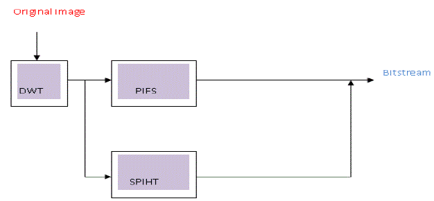
| The block diagram of the Fractal based wavelet encoder is shown in Fig2 The image is decomposed into several subbands by applying DWT (discrete wavelet transform). Haar wavelet is applied two times to the original image. It transforms the image into wavelet coefficients. The approximation subband wavelet coefficients are taken from the transformed image. It is given to PIFS and the remaining coefficients are given to SPIHT. The image is divided into range blocks. The variance of range blocks are calculated. Most existing high performance image coders in applications are transform based coder . In the transform coder, the image pixels are converted from the spatial domain to the transform domain through a linear orthogonal or bi-orthogonal transform. This is the key to achieve an efficient coding (i.e., high compression ratio). Indeed, since most of the energy rests in a few large transform coefficients, we may adopt entropy coding schemes. |
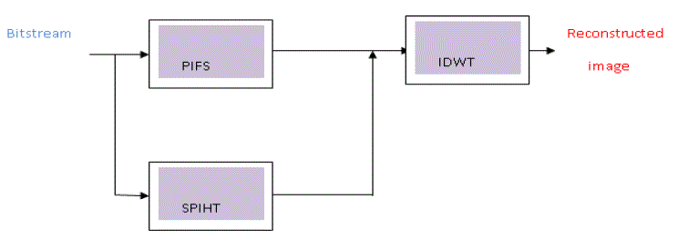
| The wavelet based fractal Compressed (WFC) image from encoder is the input to the corresponding decoder. The coded file is read one by one. If the bit is 1, then the block is replaced by mean pixel. If it is 0, then the subsequent block position is read from coded file. Hence, the block is replaced by the corresponding domain block which is taken from domain pool using block position. The compressed image from SPIHT is given to its equivalent decoder. Inverse DWT operation for all blocks is performed to recover the reconstructed image. The block diagram of Hybrid Fractal wavelet decoder is shown in fig 3. |
| D. Hybrid fractal wavelet fractal compression |
| The motivation for these methods stems from the existence of self similarities in the multi-resolutional wavelet representation. In fact, fractal image coding in the wavelet domain (Ma, 1998) has quite different characteristics from the spatial domain coders and can be interpreted as the prediction of a set of wavelet coefficients in the higher frequency subbands from those in the lower ones. A contractive mapping associates a domain tree of wavelet coefficients with a range tree that it approximates. Various structures have been used for the domain to range mappings. The potential of applying the theory of iterated function systems to the problem of image compression was recognized by Barnsley and Sloan (1988). They patented their idea in 1990 and 1991. A method of fractal encoding that utilizes a system of domain and range sub image blocks was introduced by Jacquin (1990a, 1990b). Wavelet transform (Mallat, 1989; Marta et al., 2003) approaches to image compression exploit redundancies in scale. Wavelet transform data can be organized into a sub tree structure that can be efficiently coded. In Hybrid fractal-wavelet techniques (Hebert and Soundararajan, 1998; Shapiro, 1998; Wenxiu et al., 2004) domain-range transformation idea of fractal encoding is applied to the realm of wavelet sub trees. Improved compression and decoded image fidelity is obtained. A range tree is fractally encoded by a bigger domain tree. The approximating procedure is very similar to that in the spatial domain: sub sampling and determining the orientation and scaling factor. Note that one does not need an additive constant because the wavelet tree does not have a constant offset. Matching the size of a domain tree with that of a range tree by truncating all coefficients in the highest subbands of the domain tree is called Subsampling. The orientation operation consists of a combination of a 90 degree rotation and a flip, and it is done within each subband. A switch of HL (High- Low) and LH (Low-High) subbands is the next step [2][13]. |
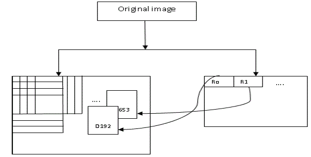
| This procedure of this fractal image compression method is shown in Figure 3. Let Dl denote the domain tree, which has its coarsest coefficients in decomposition level l, and let Rl-1 denote the range tree, which has its coarsest coefficients in decomposition level l-1. The contractive transformation (T) from domain tree Dl to range tree Rl-1, is given by |
 (1) (1) |
| where S denotes sub sampling and α is the scaling factor. |
 |
 |
| Let be the ordered set of coefficients of a range tree and the ordered set of coefficients of a down sampled domain tree. Then, the mean squared error is given by Equation 4. |
 |
| And the optimal α is obtained by Equation . |
 |
| We should search in the domain tree to find the best matching domain block tree for a given range block tree. The encoded parameters are the position of the domain tree and the scaling factor. It should not be left unmentioned that in this algorithm, the rotation and flipping have not been implemented. To increase the accuracy of scale factors, new scheme of Wavelet fractal compression is introduced [8]. In this approach, α in contrast to the previous method which had to be calculated for each block tree individually, is computed for each level separately, hence the more α s and the better quality achieved. |
| E. Set partitioning in hierarchical tree (SPIHT) |
| Image compression plays a major role in multimedia applications. Many powerful and complex wavelet-based image compression schemes [3] have been developed over the past few years. Among them, SPIHT [11] is the well recognized coding method because of its excellent RD performance. However, it does not entirely provide the desired features of progressive transmission and spatial scalability due to the algorithm uses an inefficient coefficient partitioning method. Moreover, a larger amount of memory is required to maintain three lists that are used for storing the coordinates of the coefficients and treesets in the coding and decoding process. A great number of operations to manipulate the memory are also required in the codec scheme, which greatly reduces the speed of the coding procedure.In this paper, we propose a modified SPIHT coding algorithm, which can reduce bits redundancy and scanning redundancy of traditional SPIHT. When scanning the collection of type-D in list of insignificant sets (LIS), if there are important coefficients in their offspring, traditional SPIHT will generate three direct child nodes of their offspring and determine the importance of child nodes to decide where to send these child nodes, list of significant pixels or list of insignificant pixels, and meanwhile it generates a L-type set to LIS. However, the probability of important coefficients being a direct descendant is not very high in practice, especially for complex image textures. |
| Therefore, we should deal with O(i, j) as a whole, and then determine the importance of the coefficients to decide whether or not to split the collection. |
| F. Image quality measure |
| The image quality can be evaluated objectively and subjectively. Objective methods are based on computable distortion measures. Standard objective measures of image quality are Mean Square Error (MSE) and Peak Signal to Noise Ratio (PSNR) which are defined as, |
 |
 |
| Where I(x,y) is the original image, I'(x,y) is the approximated version (which is actually the decompressed image) and M,N are the dimensions of the images. MSE and PSNR are the most common methods for measuring the quality of compressed images, despite the fact that they are not adequate as perceptually meaningful measures of image quality. Equation (2) is for commonly used 8bpp images. In image compression systems, the truly definitive measure of image quality is perceptual quality. |
| In the image compression literature using two quality metrics for evaluation, compression ratio (CR) and peak signal to noise ratio (PSNR), are very common such that most of the papers have been used in this study, assessed the performance of their algorithm by using PSNR. Due to this and to be able to compare the results with other image compression methods, we utilized PSNR. CR is defined as the volume of the original image (as the number of bits) divided by the volume of the compressed image (as the number of bits) given in Equation 1 [14]. Compression ratio is the compression efficiency is defined by the parameter compression ratio (CR) and is given by, |
 |
 |
 |
IV. RESULT AND DISCUSSION
|
| A. Performance of DWT and PIFS Algorithm |
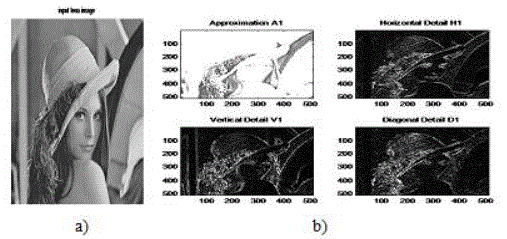
| For typical test images of size 512 × 512 in the experiments, range and domain blocks of sizes 16 × 16 and 32 × 32, respectively are considered. In wavelet-fractal image compression algorithm, first we decompose the lena image by 5- level Haar wavelet transform shown in fig. Then, the block sizes of 8x8, 4x4, 2x2 and 1x1 were used from the high frequency subbands to low frequency subbands, and searched for the best pair with the same block size 8x8, 4x4, 2x2 and 1x1 within the downsampled images in the subbands with one level less. The pair matching is performed between the subbands of the 1, 2, 3, and 4 levels as domain pool and downsampled of subbands of 2, 3, 4, and 5 levels as range block, respectively. The calculation of scale factor is performed through equation (5). |
| Above fig6 is input gray image of lena 512×512 is applied to 1-level haar wavelet decomposition implemented in MATLAB that gives the approximation result of 1-level in for example approximation A1,horizontal A1,vertical A1,Diagonal A1 in details with input image. All these result are totally depends on the applied image to the haar wavelet in four ways first approximately, second horizontal, third vertical and forth diagonal. It will gives the information of image which is to be generated in wavelet coefficient .so these all figure show the 1-level decomposition in details [4]. |
| Itearation based image compression as shown in fig7. this fig gives the comparision of visual quality in image,first fig a) has a more blurring part in image.Then reconstruction with second iteration we got the good quality ,afterward we increase the number of iteration upto 5 number we got the original image. Comaparision of iteration present in table. |
| Table 1gives the values of Mean square error and peak to signal ratio at different iteration and fixed value of bit per pixel and the compression ratio. It illustrates that the very less bit rate its compression ratio is very high this property is used to reduced the space required to uncompressed image. This table also gives the comparison of the encoding time and the decoding time ,we observed that in first iteration compression and decompression take less time as compared to 5 number. Simulation is carried out here with lena images of size 512*512. We increased the iteration PSNR also increased from 20.96dB to 29.26. |
| Table2 gives the the comparison with three images applied to the PIFS algorithm with the same size of images .First image lena with size of 512*512 gives the 29.23dB and CR=56.88:1,BPP=0.5625,encoding time and decoding time. Second is lighthouse gray image of size 512*512 is applied to PIFS we got the PSNR=24.17,MSE=248.55 its increased as compared the lena images .Third is the peppers gray image gives the value are as PSNR=29.13dB,MSE=79.31 observed here we changed the images with similar size then value of PSNR and the MSE are not same. |
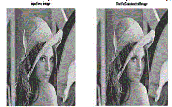
| Following fig 8. is the reconstructed and original lena images using the wavelet based fractal compression and decompression we observed that reconstructed image is similar to original image. |
| H. Performance of SPIHT Algorithm |
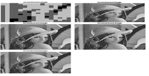
| The SPIHT algorithm does not use any point interception stream approach, and the interception approach using quantitative threshold decision method, means that each time quantitative threshold scan must be completed. After the scanning is completed, determination will be taken on the resulting stream to decide whether to continue scanning the next level of quantization threshold scan. So with this implementation, at the same compression ratio the SPIHT and the traditional SPIHT method both have the same peak signal-to-noise ratio (PSNR) after the reconstruction of generated code stream to the image. Fig shows that the reconstructed images of different rate with fixed level of decomposition, now we observed here rate is 0.01 reconstructed image is blured not similar to original image we increased the compression rate images quality also vary and last image look like same image. |
| Table 3 gives the the comparison with three images applied to the SPIHT algorithm with the same size of images .First image lena with size of 512*512 gives the 29.23dB and CR=56.88:1,BPP=0.5625,encoding time and decoding time. Second is lighthouse gray image of size 512*512 is applied to PIFS we got the PSNR=24.17,MSE=248.55 its increased as compared the lena images .Third is the peppers gray image gives the value are as PSNR=29.13dB,MSE=79.31 observed here we changed the images with similar size then value of PSNR and the MSE |
V. CONCLUSION
|
| In this paper we analysed the haar wavelet of 5-level decomposition for image compression .We have used various types of standard images for illustration purpose. We used lena with 512*512 size of image. We have got the higher PSNR near about 29.16dB as compared to SPIHT algorithm at bitrate equal to 0.50 ,then we got the PSNR =29.16dB .We have evaluated a hybrid wavelet-fractal coder on images and also SPIHT algorithm .We have observed that the higher compression in low bit rate. |
| |
Tables at a glance
|
|
|
Figures at a glance
|
 |
 |
 |
 |
 |
| Figure 1 |
Figure 2 |
Figure 3 |
Figure 4 |
Figure 5 |
 |
 |
 |
 |
| Figure 6 |
Figure 7 |
Figure 8 |
Figure 9 |
|
| |
References
|
- Jyh-HorngJeng, “Study on Huber Fractal Image Compression” IEEE Transactions on Image Processing, vol.18,pp.1- 5,may 2009.
- YuzoIano, Fernando Silvestre da Silva “A Fast and Efficient Hybrid Fractal-Wavelet Image Coder”, IEEE Transactions on Image Processing,vol. 15,pp 1, jan 2006.
- L.W. Chew, L.-M.Ang, and K. P. Seng, “New virtual SPIHT trees structures for very low memory strip-based image compression,” IEEESignal Processing Letters, vol. 15, pp. 389–392, sept 2008.
- Mohsen Ghazel, George H. Freeman, and Edward R. Vrscay “Fractal-Wavelet Image Denoising Revisited” IEEE Transactions on ImageProcessing, vol. 15,pp 9, SEP 2006
- Geoffrey M. Davis ,“A Wavelet-Based Analysis of Fractal Image Compression” IEEE Transactions on Image Processing , vol.7, pp 2, FEB1998.
- DietmarSaupe, Matthias Ruhl “Evolutionary fractal image compression” IEEE International Conference on Image Processing (ICIP'96),Lausanne, Sept. 1996.
- Jacquin, “Image coding based on a fractal theory of iterated contractive image transformations,” IEEE Transactions Image Processing, Vol. 1,pp. 18–30, Jan. (1992).
- Chun-Lung Hsu, Member, IEEE, Yu-Sheng Huang, Ming-Da Chang, and Hung-Yen Huang, “Design of an Error-Tolerance Scheme forDiscrete Wavelet Transform in JPEG 2000 Encoder” IEEE Transaction on computers, vol.60,pp. 5, may 2011.
- Zhijun Fang, NaixueXiong, Member, IEEE, Laurence T. Yang, Member, IEEE, Xingming Sun, and Yan Yang, “Interpolation-Based
- Direction-Adaptive Lifting DWT and Modified SPIHT for Image Compression in Multimedia Communications” IEEE System journal, vol.5, pp 4, dec 2011
- Yongseok Jin, Member, IEEE, and Hyuk-Jae Lee “A Block-Based Pass-Parallel SPIHT Algorithm” IEEE Transactions on circuit and systemfor video technology, vol.22, NO. 7, july 2012.
- J. Nadenau, J. Reichel, and M. Kunt, “Wavelet Based Color Image Compression: Exploiting the Contrast Sensitivity Function,” IEEE Transactions Image Processing, Vol. 12, no.1, Pp. 58-70, may 2003.
- G.Sadashivappa, K.V.S. AnandaBabu, “Evaluation of Wavelet Filters for Image Compression “World Academy of Science, Engineeringand Technology 51 ,pp 56-65 ,may 2009.
- Arnaud E. Jacquit, MEMBER, IEEE “Fractal Image Coding: A Review” IEEE, vol 81, pp. 10, oct 1993.
- Rafael C. Gonzalez ,Richard E. Woods, “Digital image processing” Pearson Education, 2002.
- Khalid Sayood“ Introduction to Data Compression” Morgan Kaufmann Publishers, 2005.16.FaizaMekhalfa and DaoudBerkani ,“Application of Hybrid Wavelet-Fractal Compression algorithm for Radiographic Images of WeldDefects”,IJNCAA,pp.45 may 2011.
- B. Sankaragomathi1, L. Ganesan2 and S. Arumugam, “Use of Wavelets in Fractal Compression Algorithm for Enhanced Performance”,IJISLM,vol.2, pp 5 dec 2010.
- MeenuBansal ,Sukhjeet K. Ranade , “A review on fractal image compression”,IJACTE,vol 1 may 2012.
|